
Related Manuals for Elation MAGIC-260


Summary of Contents for Elation MAGIC-260
- Page 1 M A G I C -2 6 0 U S E R M A N U A L Version 04-06 Rev 1.0 Elation Professional · Los Angeles, Ca 90058 · www.elationlighting.com...
-
Page 2: Table Of Contents
26: USB Load Memory to Computer………………………………………………………………………………………………...30 27: USB Memory transfer to stick from Computer………………………………..……………………………………………31 28: USB Memory Delete Files & Format Stick…………..……………………………………………………………………….31 29: USB Memory Reload to Magic 260……………………………………………………………………………………….…...32 30: Erase All Memory…………………………………………………………………………………………………………….……..…33 31: Midi…………………………………………………………………………………………………………………………………..….….34 Elation Professional · Los Angeles, Ca 90058 · www.elationlighting.com... -
Page 3: General Introduction
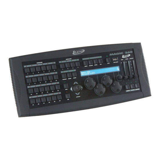
M A G I C - 2 6 0 Section 1: General Introduction Thank you for choosing the Elation MAGIC-260. The MAGIC -260 is a 264 channel, extremely user friendly, DMX lighting controller designed for DJ’s, night clubs and bars. Magic 260 includes an on board help button that offers step by step instructions on programming scenes and shows in both English and Spanish. -
Page 4: Safety Information & Maintenance
Section: 2 Safety Information & Maintenance Please read all instructions prior to assembling, mounting, and operating your MAGIC-260. To protect against fire, electric shock and injury to persons, please follow the safety precautions listed below and observe all warnings in this manual and warnings printed on the console. The following rules give important information regarding safety during operation and maintenance for long term use. -
Page 5: Information Notice
Section 4: Product Registration & Warranty Information The MAGIC-260 carries a one year limited warranty. Please fill out the enclosed warranty card to validate your purchase. All returned service items whether under warranty or not, must be freight prepaid and accompany a return authorization, (R.A., number). -
Page 6: Features And Specifications
M A G I C - 2 6 0 Section 5: Features and Specifications Moving light controller for up to 24 moving lights. Help button for programming scenes and shows. 264 total DMX channels. 4 Auxiliary buttons for manual On/Off control via DMX power pack (power pack not included). ... -
Page 7: Front Panel Overview
Section 6: Front Panel Overview 14 15 FUNCTION buttons: The FUNCTION buttons are multipurpose buttons used in conjunction with the FIXTURE, SCENE and SHOW buttons. When the FIXTURE button is active, these buttons act as FIXTURE buttons. When the SCENE button is active, these buttons act as SCENE buttons and when the SHOW button is active, these buttons act as SHOW buttons. - Page 8 Continue Section 6: Front Panel Overview MENU button: The MENU button should be pressed when wanting to access any setup options and sub menus. This includes fixture set up, fixture patch, multi fixture, pan/tilt invert, midi set up, saving memory file, loading memory file, saving fixture set up file, loading fixture set up file, formatting USB MEM/Stick, viewing free memory on USB MEM/Stick and updating controller software.
- Page 9 Continue Section 6: Front Panel Overview 11. FADE fader: The FADE fader is used during show playback. Adjusting the fade fader before or during show playback will temporarily change the programmed fade time to run at the current setting. 12. SPEED fader: The SPEED fader is used during show playback.
- Page 10 Continue Section 6: Front Panel Overview 23. Small DATA wheel: The small DATA wheel, wheel # 5, is used to view additional fixture channels. Four fixtures channels can be viewed in the LCD at a time. When this wheel is turned clockwise, the fixtures next four channels will display in the LCD.
-
Page 11: Rear Panel Overview
Section 7: Rear Panel Overview LCD BACK LIGHT knob : The LCD BACK LIGHT knob should be used to adjust the LCD brightness. Turn counter clockwise to make the display brighter and clockwise to make it less bright. AUDIO RCA input: The AUDIO input should be used when wanting to synchronize show steps to an audio source. -
Page 12: Flow Chart
This flow chart shows you the order which should be followed when setting up & programming moving light fixtures with the MAGIC-260. Be sure to follow the flow chart in the exact order described to insure proper setup, programming and playback procedures. -
Page 13: 11: Choose Fixtures
If the fixture profile that you require is not posted on our site, please contact Elation Professional support at support@elationlighting.com... - Page 14 Section 11: Choose Fixtures (Continue) (3) You will get a momentary 3 second warning in the LCD that reads as follows: THIS FIXTURE DOES NOT MATCH RECORD & PATCH MEMORY ? Followed by: DO YOU WISH TO CONTINUE? The reason f or this message is the internal memory does not recogniz e the newly sel ected fi xture as being part of any Scenes or Shows currently stored in the consol e .
-
Page 15: 12: Patch Fixtures
Section 12: Patch Fixtures The Patch Fixture menu option allows you to view and make changes to your fixture address patch if desired. Because the Magic 260 utilizes fixture profiles, you can set your DMX addresses based on the Channel setting in the Patch Fixture option. - Page 16 Section 12: Patch Fixtures (Continue) The factory default setting for the Autopatch feature is “ON”. It is recommended that you leave this setting set to “ON” and proceed to step (4). With this setting set to “ON”, each fixture address is automatically patched for you. If you decide that you must set your own patch addresses, first change “ON”...
-
Page 17: 13: Auxiliary Buttons
Section 13: AUXILIARY BUTTONS (1-4) T he AUXILIRARY buttons wi ll all o w you to switch non DMX fixtures ON/OFF via a univers al D MX pac k. T his allows you to co ntrol up to 4 dance to s ound ef fects and your intelligent lights from M agic 260. -
Page 18: 16: Record Scenes
Section 1 6: Record Scenes This next section will take you through the necessary steps to record scenes. 1,152 scenes can be stored into Magic 260’s memory via 48 pages. The 24 Function buttons should be used to store and playback scenes when the “SCENE”... -
Page 19: 17: Presets
Section 16 : R ecord Scenes (Continue) (9) Turn DATA wheel #4 to the page that you wish to save your scene to. Note: if there is a FUNCTION LED illuminated ON solid, it means there is already a scene stored there. Unless you want to record over the existing scene, it is recommended that you store to a button that has its’... - Page 20 Preset Movement & Record Movement as a Scene (Continue) Play (5) FUNCTION buttons 1-6 contain the preset movements. 1 = Circle CW, 2 = Circle CCW, 3 = Figure 8 CW, 4 = Figure 8 CCW, 5 = Pan Movement & 6 = Tilt Movement. Press the FUNCTION button that contains the preset movement you wish to play.
- Page 21 Edit Preset Movement Offset Point and R adius (1) Press the FIXTURE button so its green LED illuminates ON solid. (2) Press the FUNCTION button or buttons that correspond with the fixture or fixtures that you wish to include into your preset. The relevant FUNCTION buttons should be flashing red and the fixture attributes should display in the LCD.
-
Page 22: 18: Record Shows
Section 1 8: Record Shows A show is a sequence of recorded scenes in which each step can incorporate different step hold times. Up to 288 shows with up to 255 steps can be stored to Magic 260s’ memory via 12 show pages. When playing back a show in auto mode, there is an internal clock that keeps track of every show cue. - Page 23 Section 1 8: Record Shows (Continue) (9) Press the ENTER button to store the show step and settings. The show step in the display should advance by 1, Scene should read “Empty” and the Hold time should have again defaulted to 5 seconds.
-
Page 24: 19: Playback Scenes
Section 1 9: Playback Scenes (1) Press the SCENE button so its green LED illuminates ON solid. (2) Turn DATA wheel #1 to select the scene page that contains the scene or scenes that you wish to playback. (3) Press the FUNCTION button (1-24) that corresponds to the scene that you wish to playback. The relevant red FUNCTION LED should illuminate and the scene should trigger ON. -
Page 25: Playback Shows
Section 20: Playback Shows (Continue) (5) While a show is playing automatically (MANUAL FEATURE ON), you can pause the show by pressing DATA wheel #4 at any time. You can then turn DATA wheel #3 clockwise to manually advance the show step and counter clockwise to go back to a desired show step. -
Page 26: Edit Scene
Section 21 : Edit Scene (Continue) (9) Press the same FUNCTION button that you pres s ed in st ep 3. M agic 260 will as k, “Do yo u want to o verwrite the old sc ene? ” (10) Press DATA wheel #3 to c onf irm “Yes ” o r DATA wheel #4 for “No”. (11) Repeat s teps 1- 10 to edit additional scenes. -
Page 27: 23: Ulink Save Memory
Section 23: ULink (Save Memory File) This operation will allow you to transfer data from your controller to a standard PC or laptop. You must first install the Magic 260 application software and USB driver that was supplied with your ULink cable. You can also download these files from the Magic 260 webpage on our website at www.elationlighting.com. -
Page 28: 24: Ulink Load Memory
Section 24: ULink (Load Memory File) This operation will allow you to transfer previously stored data from your computer back into your Magic 260. You must first install the Magic 260 application software and USB driver that was supplied with your ULink cable. You can also download these files from the Magic 260 webpage on our website at you’ve misplaced or lost your software disc. -
Page 29: 25: Usb Save Memory
Section 24: ULink (Load Memory File) (Continue) (8) On your computer, click “Send File”. A Send window will pop up. Select the destination and memory file that you want to load into Magic 260 and click “Open”. (A message should appear in the lower right hand corner that reads “Sending”). -
Page 30: 26: Usb Load Memory To Computer
Section 25: USB MEM Stick (Save Memory File)(Continue) On the Magic 260, press DATA wheel #2 to select USB. Your display should read the following: Please set this file name, then (enter) UNNAME00 (6) If you want to name the file, turn DATA wheel #1 to change the character and turn DATA wheel #5 to move the cursor over under the next character. -
Page 31: 27: Usb Memory Transfer To Stick From Computer
Section 27: USB MEM Stick (Reload Memory File to USB MEM Stick from Computer) This operation will allow you to load your Magic 260 memory files from your computer to your USB MEM Stick. You must first install the Magic 260 application software and USB driver that was supplied with your USB MEM Stick. -
Page 32: 29: Usb Memory Reload To Magic 260
Section 29: USB MEM Stick (Load Memory File) This operation will allow you to transfer data from your USB Memory stick back into Magic 260. (1) Install the USB MEM Stick into the USB port on your Magic 260. (2) Flip the power switch OFF then back ON. (3) On the Magic 260, press the MENU button so your display reads the following: Select a menu item then press enter. -
Page 33: 30: Erase All Memory
Section 30: Erase All Memory The next set of instructions will allow for ALL programmed memory, including presets, scenes and shows, to be erased in one shot. (1) From the main screen, press and hold down the “DEL” button then press the “ENTER” button once. Your display will read as follows: Select a menu item then press enter. -
Page 34: 31: Midi
Section 31: Midi Midi Channel Midi Chart Value 0-72 (Scene 1-3) 0-72 (Scene 4-6) 0-72 (Scene 7-9) 0-72 (Scene 10-12) 0-72 (Scene 13-15) 0-72 (Scene 16-18) 0-72 (Scene 19-21) 0-72 (Scene 22-24) 0-72 (Scene 25-27) 0-72 (Scene 28-29) 0-72 (Scene 30-32) 0-72 (Scene 33-35) 0-72 (Scene 36-38) 0-72 (Scene 39-41)