Table of Contents
Advertisement
Repair
™
390
Electric Airless
Sprayer
- For portable spray application of architectural paints and coatings -
Models: 253958, 262019, 254968, 254969, 254998, 253961
Maximum Working Pressure: 3300 psi (227 bar, 22.7 MPa)
IMPORTANT SAFETY INSTRUCTIONS!
Read all warnings and instructions. Save these instructions. Contact Graco Customer Service
or your local Graco distributor to obtain a manual in your language.
Stand
Graco Inc. P.O. Box 1441 Minneapolis, MN 55440-1441
Copyright 2006, Graco Inc. is registered to I.S. EN ISO 9001
ti5635b
311737B
Related Manuals
311732
309639
309250
311761
ti11626a
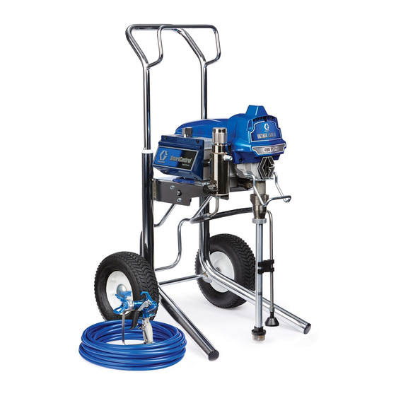
Hi-Boy
Advertisement
Table of Contents

Related Manuals for Graco 390 Electric Airless Sprayer


Summary of Contents for Graco 390 Electric Airless Sprayer
- Page 1 Models: 253958, 262019, 254968, 254969, 254998, 253961 Maximum Working Pressure: 3300 psi (227 bar, 22.7 MPa) IMPORTANT SAFETY INSTRUCTIONS! Read all warnings and instructions. Save these instructions. Contact Graco Customer Service or your local Graco distributor to obtain a manual in your language. Related Manuals...
- Page 2 Models Models Model 253358 262019 254968 — 230 CCE 254969 — 230 Europe 253961 — 110 UK 254988 — 230 Asia 311737B...
- Page 3 Warning Warning The following warnings are for the setup, use, grounding, maintenance and repair of this equipment. The exclamation point symbol alerts you to a general warning and the hazard symbol refers to procedure-specific risks. Refer back to these warnings. Additional, product-specific warnings may be found throughout the body of this manual where appli- cable.
- Page 4 Read fluid and solvent manufacturer’s warnings. For complete information about your material, request MSDS from distributor or retailer. • Check equipment daily. Repair or replace worn or damaged parts immediately with genuine Graco replacement parts only. • Do not alter or modify equipment.
-
Page 5: Component Identification
Component Identification Component Identification Stand ti5636c Item Component Pressure Control ON/OFF switch Pressure Gauge (not on all models) Power Cord Fluid Outlet Prime Valve Cord Wrap Pump Suction Hose Drain Hose Fluid Hose Guard Trigger Safety Lock Serial Number ID Label Filter Cover 311737B... - Page 6 Component Identification Hi-Boy ti11629a Item Component Pressure Control ON/OFF switch Power Cord Fluid Outlet Prime Valve Cord Wrap Pump Suction Hose Drain Hose Fluid Hose Guard Trigger Safety Lock Serial Number ID Label Filter Cover 311737B...
-
Page 7: Installation
Installation Installation Grounding and Electric Do not use the sprayer if the electrical cord has a dam- aged ground contact. Only use an extension cord with Requirements an undamaged ground contact. The sprayer cord includes a grounding wire with an appropriate grounding contact. -
Page 8: Pressure Relief Procedure
Pressure Relief Procedure Pressure Relief Procedure 3. Turn prime valve down. Follow this Pressure Relief Procedure whenever you are instructed to relieve pressure, stop spraying, check or service equipment or install or clean spray tip. ti8326a 1. Turn OFF power and turn pressure control to lowest pressure setting. -
Page 9: General Repair Information
General Repair Information General Repair Information To reduce risk of serious injury, including electric shock: • Do not touch moving or electric parts with fingers or tools while testing repair. • Unplug sprayer when power is not required for Flammable materials spilled on hot, bare, motor testing. -
Page 10: Troubleshooting
Troubleshooting Troubleshooting What To Check What To Do Problem (If check is OK, go to next check) (When check is not OK, refer to this column) Motor Won’t Operate Basic Fluid Pressure 1. Pressure control knob setting. Slowly increase pressure setting to see if motor Motor will not run if set at mini- starts. - Page 11 Troubleshooting What To Check What To Do Problem (If check is OK, go to next check) (When check is not OK, refer to this column) Basic Electrical 1. Electric supply. Meter must read Reset building circuit breaker, replace building See wiring diagram, page 100-130 VAC for 110-120 VAC fuses.
- Page 12 Troubleshooting What To Check What To Do Problem (If check is OK, go to next check) (When check is not OK, refer to this column) Low Output 1. Worn spray tip. Relieve pressure, page 8. Replace tip. Refer to gun instruction manual, 309639. 2.
- Page 13 Troubleshooting What To Check What To Do Problem (If check is OK, go to next check) (When check is not OK, refer to this column) Motor runs and pump 1. Prime Valve Open. Close prime valve. strokes 2. Paint supply. Refill and reprime pump.
-
Page 14: Displacement Pump Replacement
Displacement Pump Replacement Displacement Pump Replacement See manual 309250 for pump repair instructions. 4. Cycle pump until pin (32) is in position to be removed. Removal 5. Disconnect power cord from outlet. 6. Using a flat screwdriver, push retaining spring (C) up. - Page 15 3. Install pump pin (32). Verify retainer spring (C) is in groove over pump pin. ti6105b 9. Fill packing nut with Graco TSL until fluid flows onto top of seal. Rotate cover (44). Tighten screws (30). ti6108b 4. Push pump (9) up until pump threads engage.
-
Page 16: Drive Housing Replacement
Drive Housing Replacement Drive Housing Replacement Installation 1. Apply a liberal coat of grease to gears and needle bearing surfaces. Install thrust bearing (4) and gears (2) and (3) in front endbell housing. Removal Needle Bearing Surfaces 1. Relieve pressure, page 8. 2. -
Page 17: Spin Test
Spin Test Spin Test See Wiring Diagram, page 28. 2. If uneven or no resistance, check for missing brush caps, broken brush springs, brush leads, and worn brushes. Repair as needed, page 19. 3. If still uneven or no resistance, replace motor, page To check armature, motor winding and brush electrical continuity: 1. -
Page 18: Fan Replacement
Fan Replacement Fan Replacement Removal 4. Pull off fan (100). Installation 1. Slide new fan (1a) in place on back of motor. Be 1. Relieve pressure, page 8. Disconnect power cord sure blades of fan face motor as shown. from outlet. 2. -
Page 19: Motor Brush Replacement
Motor Brush Replacement Motor Brush Replacement See Wiring Diagram, page 28. 2. Push each cap (A) into place over brush. Orient each cap with the 2 projections on either side of the brush lead. You will hear a “snap” when cap is Removal securely in place. -
Page 20: Control Board Replacement
Control Board Replacement Control Board Replacement See Wiring Diagram, page 28. 6. Pull control board out slightly and then slide it back and off of frame. Make sure power cord is free and NOT wrapped around cord wrap. Removal 7. Remove grommet and wires from strain relief. 1. - Page 21 Control Board Replacement Installation 3. Carefully slide control board back into place on the side of the motor frame. 1. Position grommet and power cord wires through strain relief in control board (33). Strain Relief Grommet ti6122a 2. Reconnect the power cord connectors to the correct ti6119b terminals indicated on the control board (120V, black and white, 240V, blue and brown) on control...
-
Page 22: Fuse Replacement
Fuse Replacement Fuse Replacement 3. Remove fuse from control board. Installation 1. Install new fuse on control board. Removal 2. Install shroud (29) and two screws (30) (see illustra- 1. Relieve pressure, page 8. Disconnect power cord tion, page 17). from outlet. -
Page 23: Pressure Control Assembly Replacement
Pressure Control Assembly Replacement Pressure Control Assembly Replacement See Wiring Diagram, page 28. 6. Turn the pressure control knob (16) counter clock- wise as far as you can to access the flats on either side of the pressure control assembly. 7. -
Page 24: Drain Valve Replacement
Drain Valve Replacement Drain Valve Replacement Installation Before installing new drain valve, be sure old gas- ket (23a) and seat (23b) are not still inside mani- Removal fold. 1. Relieve pressure, page 8. Disconnect power cord 1. Thread drain valve (23) into manifold (15) opening. from outlet. - Page 25 Drain Line Removal/Replacement Drain Line Removal/Replacement Removal Installation To remove the drain line (40) from the manifold: 1. Screw barbed fitting (20) into manifold. 2. Push drain line (40) onto barbed fitting (20). 1. Cut drain line (40) from barbed fitting (20). 2.
-
Page 26: Power Cord Replacement
Power Cord Replacement Power Cord Replacement Installation See Wiring Diagram, page 28. 1. Follow Control Board Replacement installation instructions, steps 1-4, page 20. 2. Reconnect, green ground wire (G) to green ground- ing screw (31) on frame. Be sure terminal on ground faces UP or wires could get caught in shroud. -
Page 27: Motor Replacement
Motor Replacement Motor Replacement See Wiring Diagram, page 28. 6. Remove ground wire (G) from motor endbell. 7. Remove four screws (6) and motor (1) from frame (45). Installation 1. Install new motor (1) on frame (45) with four screws CAUTION (6). -
Page 28: Wiring Diagram
Wiring Diagram Wiring Diagram 120V Model from Mo or Red (+) 2 x Yellow Bl ck (-) Repl ce ble Fuse Pressure Con rol Assembly ON/OFF Sw ch Bl ck C p c or Power Wh e Plug Green ti5643a Pressure Con rol 240V Model Assembly... -
Page 29: Technical Data
Technical Data Technical Data Power requirements ......100/120V AC, 50/60 hz, 11A, 1 phase 230V AC, 50/60 hz, 7.5A, 1 phase Generator required . - Page 30 Notes Notes 311737B...
-
Page 31: Warranty
With the exception of any special, extended, or limited warranty published by Graco, Graco will, for a period of twelve months from the date of sale, repair or replace any part of the equipment determined by Graco to be defective. - Page 32 Warranty TO PLACE AN ORDER, contact your Graco distributor, or call 1-800-690-2894 to identify the nearest distributor. All written and visual data contained in this document reflects the latest product information available at the time of publication. Graco reserves the right to make changes at any time without notice.