Sony VPL-FX30 Operating Instructions Manual
Operating instructions
Hide thumbs
Also See for VPL-FX30:
- Brochure & specs (8 pages) ,
- Quick reference manual (148 pages) ,
- Manual (116 pages)
Table of Contents
Advertisement
Data
Projector
Operating Instructions
Before operating the unit, please read this manual and supplied Quick Reference Manual
thoroughly and retain it for future reference.
VPL-FX35/FX30
Not all models are available in all countries and area. Please check
with your local Sony Authorized Dealer.
© 2010 Sony Corporation
4-186-250-12 (1)
Advertisement
Table of Contents

Related Manuals for Sony VPL-FX30


Summary of Contents for Sony VPL-FX30
-
Page 1: Operating Instructions
Before operating the unit, please read this manual and supplied Quick Reference Manual thoroughly and retain it for future reference. VPL-FX35/FX30 Not all models are available in all countries and area. Please check with your local Sony Authorized Dealer. © 2010 Sony Corporation... -
Page 2: Table Of Contents
Table of Contents Overview Network Location and Function of Controls ..3 Using Network Features ....24 Main Unit ........3 Displaying the Control Window of the Projector with a Web Connector Panel ......4 Browser ........24 Remote Commander and Control Confirming the Information Panel .......... -
Page 3: Location And Function Of Controls
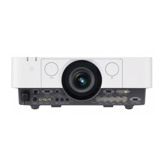
B Overview Location and Function of Controls Main Unit qa qd9q;4 1 4 5 3 qs qg qh a Lens (page 34) l Connector panel (page 4) b Focus ring (page 13) m Remote control detector The remote control detectors are located c Zoom lever (page 13) at the front and rear of the projector. -
Page 4: Connector Panel
Connector Panel q; 8 45 23 Input (pages 8) Output (page 11) a INPUT A f OUTPUT Video: RGB/YP input connector Video: Monitor output connector (RGB HD VD/YP (MONITOR) Audio: Audio input connector (AUDIO) Audio: Audio output connector (AUDIO) b INPUT B Note Video: RGB input connector (RGB) This connector outputs the projected image or... -
Page 5: Remote Commander And Control Panel
Remote Commander and Control Panel Remote Commander b Selecting an input signal (page 12) INPUT key (main unit) Direct input select keys (Remote STANDBY Commander) The D, E, and F buttons are not provided INPUT in this projector. c Operating a menu (page 15) VIDEO VIDEO ENTER /V/v/B/b (arrow) keys... - Page 6 e Using various functions during ECO Mode Menu projecting ECO Mode D ZOOM (Digital Zoom) +/– key Enlarges a portion of the image while User projecting. 1 Press the D ZOOM + key to display Back the digital zoom icon on the projected 2 Press the V/v key or ECO MODE key image.
- Page 7 i CONTROL S output connector Connects to the CONTROL S input connector on the projector with a connecting cable (stereo mini plug (not supplied)) when using the Remote Commander as a wired one. You do not need to install batteries in the Remote Commander, as the power is supplied from the projector.
-
Page 8: Connecting The Projector
B Preparation Connecting the Projector Notes • Turn off all equipment before making any connections. • Use the proper cables for each connection. • Insert the cable plugs firmly; Loose connections may reduce performance of picture signals or cause a malfunction. When pulling out a cable, be sure to grip it by the plug, not the cable itself. •... -
Page 9: Connecting A Video Equipment
INPUT C For connecting a computer with a DVI-D output connector. DVI-D output DVI-D cable connector (not supplied) Audio output connector Audio cable Computer (Stereo mini plug) (not supplied) Connecting a Video Equipment Connections with a VHS video deck, DVD player, or BD player are explained for each input signal. - Page 10 VIDEO IN For connecting video equipment with a video output connector. Video output Video cable connector (not supplied) Audio output connector Video equipment Audio cable (Phone plug × 2) (not supplied) INPUT A For connection when there is some long distance between the video equipment and projector. Component –...
-
Page 11: Connecting An External Monitor And Audio Equipment
Connecting an External Monitor and Audio Equipment OUTPUT Projected images and input audio can be output to display equipment such as a monitor and audio equipment such as speakers with a built-in amplifier. Display equipment Mini D-sub 15- RGB input pin cable connector (not supplied) -
Page 12: Projecting/Adjusting An Image
B Projecting/Adjusting an Image Projecting an Image The size of a projected image depends on the distance between the projector and screen. Install the projector so that the projected image fits the screen size. For details on projection distances “Projection Distance and Lens Shift Range” (page 42) and projected image sizes, see Input Video... -
Page 13: Adjusting The Focus, Size, And Position Of The Projected Image
Adjusting the Focus, Size, and Position of the Projected image Focus Size (Zoom) Position (Lens shift) Adjusting the tilt of the projector with the adjusters When the projector is installed on an uneven surface and the projected position is low, you can adjust using the adjusters. -
Page 14: Turning Off The Power
Turning Off the Power Press the ?/1 key on the main unit or the 1 key on the Remote Commander. The message appears if you press the key on the main unit. Press it again according to the message. Unplug the AC power cord from the wall outlet. -
Page 15: Using A Menu
B Adjustments and Settings Using a Menu Using a MENU Note The menu displays used for the explanation below may be different depending on the model you are using. RETURN key. Also, to reset the setting Press the MENU key to display the value of an item to its factory preset menu. -
Page 16: The Picture Menu
The Picture Menu For adjusting the picture for each input signal. Setting items Description Picture Mode Dynamic: Emphasizes the contrast to produce a “dynamic” picture. Standard: Makes the picture be natural and well balanced. Presentation : Makes the picture bright to suit for a presentation. Reset The picture settings are initialized to their factory preset values. -
Page 17: The Screen Menu
The Screen Menu For adjusting the size, position, and aspect ratio of the projected image for each input signal. Setting items Description Aspect Changes the aspect ratio of the projected image. (page 18). When the Normal: Displays the image on the center point of the projected image computer without changing the resolution of the input signal or enlarging the image. - Page 18 Aspect *1: If you select “Normal,” the image is Input signal Recommended projected in the same resolution as the setting value and input signal without changing the aspect projected image ratio of the original image. (4:3) (Full1) *2: If you select “Full2,” the image is projected to fit the projected image size, regardless *1 *2 (16:9)
-
Page 19: The Function Menu
The Function Menu The Function menu is used for setting various functions of the projector. Setting items Description Audio Output Vol. The higher the setting, the higher an audio level output from the audio output connector. The lower the setting, the lower the audio level. Smart APA On/Off;... -
Page 20: The Operation Menu
Note *1: You will not be able to use the projector if you forget your password. If you call qualified Sony personnel because you have forgotten the password, you will be asked to verify the projector’s serial number and your identity. -
Page 21: The Connection/Power Menu
The Connection/Power Menu The Connection/Power menu is used for setting for the connections and power. Setting items Description Network Setting IP Address Setup Auto (DHCP): The IP address is assigned automatically from the DHCP server such as a router. Manual: To specify the IP Address manually. IP Address/ Subnet When “Manual”... -
Page 22: The Installation Menu
The Installation Menu The Installation menu is used for installing the projector. Setting items Description Image Flip HV/H/V/Off: Flips the projected image horizontally and/or vertically according to the installation method. Installation Attitude Right Side Up/Upside Down: Change the cooling setting to suit to the installation attitude. -
Page 23: The Information Menu
The Information Menu The Information menu enables you to confirm various information on the projector, such as the total usage hours of a lamp. Items Description Model Name Displays the model name. Serial No. Displays the serial number. fH / fV (horizontal Displays the horizontal frequency/vertical frequency of the current input frequency/vertical signal. -
Page 24: Using Network Features
B Network Using Network Features Connection to the network allows you to operate the following features: • Checking the current status of the projector via a Web browser. • Remotely controlling the projector via a Web browser. • Receiving the e-mail report for the projector. •... -
Page 25: Confirming The Information Regarding The Projector
(*****) that was set. Using the e-mail report Note Function If you forget your password, consult with qualified Sony personnel. Set the e-mail report function on the Setup page. Entered values will not be applied unless you click on [Apply]. - Page 26 Enter the outgoing e-mail address in Click on [Owner information] to enter the Email Address box then check the the owner information recorded in the mail report. Report Timing check box of the e-mail report to be sent. Set the mail account for sending e- mail reports.
-
Page 27: Indicators
Flashes in red The projector is in abnormal status. Symptoms are indicated by number of flashes. Address the problem in accordance with the following. If the symptom is shown again, consult with qualified Sony personnel. Flashes twice The internal temperature is unusually high. Check the items below. -
Page 28: Messages List
Messages List When any of the messages listed below appears on the projected image, address the problem in accordance with the table below. Message Meaning/Remedy Page High temp.! Lamp off in Check the items below. 3, 22, 1 min. • Check to see if nothing is blocking the ventilation holes. •... -
Page 29: Troubleshooting
Troubleshooting Before asking to have the projector repaired, try to diagnose the problem, following the instructions below. Symptom Remedy Page The power is not turned Check if the AC power cord is firmly connected. – When the “Panel Key Lock” is set to “On,” you cannot turn on the projector using the ?/1 key on the projector. - Page 30 Symptom Remedy Page No sound. Check that the connecting cables between the projector and external video or audio equipment are securely connected. Check if the output setting of connected external audio – equipment is set for output the audio signal from the projector. Audio is not output if audio muting is activated.
-
Page 31: Replacing The Lamp
Replace the lamp with a new one if a message displayed on the projected image or the LAMP/ COVER indicator notifies you to replace the lamp (page 27). Use an LMP-F230 projector lamp (for VPL-FX30)(not supplied), LMP-F272 projector lamp (for VPL-FX35)(not supplied) for replacement. - Page 32 Insert the new lamp all the way in until it is securely in place. Tighten the three screws. New lamp grab Screws Close the rear panel and tighten the three screws. Note Be sure to install the lamp and rear panel securely as it was.
-
Page 33: Cleaning The Air Filter
If the dust cannot be removed from the air filter even after cleaning, replace the air filter with a new one. For details on a new air filter, consult with qualified Sony personnel. Caution If you neglect to clean the air filter, dust may accumulate, clogging it. As a result, the temperature may rise inside the unit, leading to a possible malfunction or fire. -
Page 34: Removing/Attaching The Projection Lens
Removing/Attaching the Projection Lens Notes • Turn off the projector and disconnect the AC power cord from a wall outlet before you remove/ attach the projection lens. • Be careful not to drop the projection lens. • Avoid removing/attaching the lens with the projector installed suspended from a ceiling. •... - Page 35 Remove the six screws that secure the Attach Part A and Part B for the lens flange section then slide it straight to adapter to the projection lens. remove. 1 Remove the lens cap. 2 First, fit Part A to the zoom gear Screws (6) section on the projection lens.
-
Page 36: Specifications
Zoom Manual (approx.1.6 ×) Focus Manual Light source VPL-FX30: High-pressure mercury lamp, 230 W type VPL-FX35: High-pressure mercury lamp, 275 W type Screen size 40" to 600" (1.02 m to 15.24 m) (when “Lamp Mode” is set to Light output VPL-FX30: 4200 lm “High”) - Page 37 –20 °C to +60 °C (–4 °F to +140 °F)/ 10% to 90% temperature/ Storage humidity Power VPL-FX30: 100 V to 240 V AC, 3.3 A to 1.3 A, 50/60 requirements VPL-FX35: 100 V to 240 V AC, 3.8 A to 1.6 A, 50/60 Power...
- Page 38 Design and specifications of the unit, including the optional accessories, are subject to change without notice. Always verify that the unit is operating properly before use. SONY WILL NOT BE LIABLE FOR DAMAGES OF ANY KIND INCLUDING, BUT NOT LIMITED TO,...
- Page 39 Pin assignment DVI-D connector (DVI-D, female) RGB input connector (Mini D-sub 15- pin, female) T.M.D.S. +5 V Power Data2– Video input Power supply (red) R input for DDC T.M.D.S. Ground (return Data2+ for +5 V) Video input (green) G T.M.D.S. Hot Plug Data2 Shield Detect...
- Page 40 Input connector Acceptable Input Signals fH [kHz]/ Resolution fV [Hz] DVI-D Computer signal 1360 × 768 47.7/60 Input connector fH [kHz]/ Resolution 1440 × 900 55.9/60 fV [Hz] DVI-D 1680 × 1050 65.3/60 640 × 350 31.5/70 1280 × 800 49.7/60 37.9/85 1920 ×...
- Page 41 displayed in its original resolution. Text and lines may be uneven. • Some actual value may differ slightly from the design values given in the table. Specifications...
-
Page 42: Projection Distance And Lens Shift Range
Projection Distance and Lens Shift Range The projection distance refers to the distance between the front of the lens and the projected surface. Projection distance L Front of the lens Projected image The lens shift range represents the distance in percent (%) by which the lens can be shifted from the center of the projected image. - Page 43 Projection distance Unit: m (inches) Projection image size Projection distance L Diagonal Width × Height Standard lens VPLL-Z1024 VPLL-Z1032 1.63 × 1.22 2.31 × 3.69 3.85 × 5.28 5.24 × 8.01 80" (2.03 m) (64 × 48) (91 × 145) (152 ×...
-
Page 44: Dimensions
Dimensions Front Unit: mm (inches) 390 (15 Center of the lens 195 (7 Bottom Unit: mm (inches) 463 (18 ø18 ( 122 (4 15 ( Center of the lens 272.6 (10 86 (3 ø18 ( 361 (14 Dimensions... - Page 45 When using the PSS-610 projector suspension support Caution Never mount the projector on the ceiling or move it by yourself. Be sure to consult with qualified Sony personnel (charged). Unit: mm (inches) 150 (5 175 (6 200 (7 231 (9...
- Page 46 The distance L’ between the front of About Trademarks the lens (center) and the front of the • Adobe Acrobat is a trademark of Adobe cabinet Systems Incorporated. Unit: mm (inches) • Kensington is a registered trademark of Lens L’ Type Kensington Technology Group.
-
Page 47: Index
Focus ........... 5, 13 Index Focus ring ..........3 Freeze ............6 Front panel ..........3 Function menu ........19 fV ............23 AC IN socket ..........4 Acceptable input signal ......40 Adjust Signal ...........17 Adjuster ..........3, 13 Gamma Mode ......... 16 Antitheft bar ..........3 Antitheft Lock ...........3 APA .............5, 17... - Page 48 Pattern ..........5, 13 Phase ............17 Zoom ............5, 13 Picture menu ........... 16 Zoom lever ..........3 Picture mode ........... 16 Picture muting ........... 6 Pin assignment ........39 Pitch ............17 Power Saving Mode ........ 21 Primary DNS ........... 21 Projecting an image .........
- Page 49 Sony Corporation...