Table of Contents
Advertisement
Quick Links
Intel
D845GVFN
Technical Product Specification
®
The Intel
Desktop Board D845GVFN may contain design defects or errors known as errata that may cause the product to deviate from published specifications. Current
characterized errata are documented in the Intel Desktop Board D845GVFN Specification Update.
®
Desktop Board
August 2004
Order Number: C83644-001
Advertisement
Table of Contents

Related Manuals for Intel BOXD845GVFNL


Summary of Contents for Intel BOXD845GVFNL
- Page 1 Order Number: C83644-001 ® The Intel Desktop Board D845GVFN may contain design defects or errors known as errata that may cause the product to deviate from published specifications. Current characterized errata are documented in the Intel Desktop Board D845GVFN Specification Update.
-
Page 2: Revision History
Intel products are not intended for use in medical, life saving, or life sustaining applications or for any other application in which the failure of the Intel product could create a situation where personal injury or death may occur. -
Page 3: Intended Audience
Preface This Technical Product Specification (TPS) specifies the board layout, components, connectors, ® power and environmental requirements, and the BIOS for the Intel Desktop Board D845GVFN. It describes the standard product and available manufacturing options. Intended Audience The TPS is intended to provide detailed, technical information about the Desktop Board D845GVFN and their components to the vendors, system integrators, and other engineers and technicians who need this level of information. - Page 4 Intel Desktop Board D845GVFN Technical Product Specification Other Common Notation Used after a signal name to identify an active-low signal (such as USBP0#) (NxnX) When used in the description of a component, N indicates component type, xn are the relative coordinates of its location on the Desktop Board D845GVFN, and X is the instance of the particular part at that general location.
-
Page 5: Table Of Contents
Board Layout ....................12 Block Diagram......................13 Online Support ......................14 Operating System Support................... 14 Design Specifications....................15 Processor ........................18 System Memory ......................19 ® Intel 845GV Chipset ....................21 ® 1.8.1 Intel Extreme Graphics Controller..............21 1.8.2 USB ....................... 26 1.8.3... - Page 6 Intel Desktop Board D845GVFN Technical Product Specification Connectors........................45 2.8.1 Back Panel Connectors ................. 46 2.8.2 Internal I/O Connectors ................. 47 2.8.3 External I/O Connectors ................52 Jumper Blocks......................56 2.9.1 Front Panel Audio Connector/Jumper Block ..........56 2.9.2 BIOS Setup Configuration Jumper Block ............57 2.10 Mechanical Considerations ..................
- Page 7 Contents 4 Error Messages and Beep Codes BIOS Error Messages ....................75 Port 80h POST Codes ....................77 Bus Initialization Checkpoints ..................81 Speaker ........................82 BIOS Beep Codes......................82 Figures Desktop Board D845GVFN Components ..............12 Block Diagram......................13 Location of the Standby Power Indicator LED on the D845GVFN Board ....
- Page 8 Intel Desktop Board D845GVFN Technical Product Specification Processor Fan Connector .................... 50 Main Power Connector....................50 Front Chassis Fan Connector ..................50 Chassis Intrusion Connector (Optional) ............... 50 Serial Port B Connector (optional) ................52 Auxiliary Front Panel Power/Sleep LED Connector ............. 53 Front Panel Connector ....................
- Page 9 Operating System Support................... 14 Design Specifications....................15 Processor ........................18 System Memory ......................19 ® Intel 845GV Chipset ....................21 I/O Controller........................ 28 1.10 Audio Subsystem ......................29 1.11 LAN Subsystem (Optional)................... 30 1.12 Hardware Management Subsystem (Optional) ............31...
-
Page 10: Overview
Intel Desktop Board D845GVFN Technical Product Specification 1.1 Overview 1.1.1 Feature Summary ® Table 1 summarizes the major features of the Intel Desktop Board D845GVFN. Table 1. Feature Summary Form Factor microATX (9.20 inches by 8.20 inches [233.68 millimeters by 208.28 millimeters]) •... -
Page 11: Manufacturing Options
1.1.2 Manufacturing Options Table 2 describes the manufacturing options on the Desktop Board D845GVFN. Not every manufacturing option is available in all marketing channels. Please contact your Intel representative to determine which manufacturing options are available to you. Table 2. -
Page 12: Board Layout
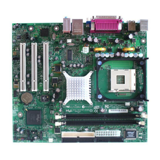
Intel Desktop Board D845GVFN Technical Product Specification 1.1.3 Board Layout Figure 1 shows the location of the major components on the Desktop Board D845GVFN. OM17296 Item Description Item Description Audio codec Diskette drive connector Intel 82562ET 10/100 Mbit/sec (PLC) device... -
Page 13: Block Diagram
Processor Socket (400/533 MHz) Intel 82845GV Intel 82801DB 3 Mbit Graphics and I/O Controller Hub Firmware Hub Memory Controller (ICH4) (FWH) Hub (GMCH) Intel 845GV Chipset CSMA/CD Display Unit Interface Interface VGA Port Memory Bus Physical DIMM Banks (2) Layer Connector... -
Page 14: Online Support
Intel Desktop Board D845GVFN Technical Product Specification 1.3 Online Support To find information about… Visit this World Wide Web site: Intel Desktop Board D845GVFN under http://www.intel.com/design/motherbd “Desktop Board Products” or “Desktop Board Support” http://support.intel.com/support/motherboards/desktop Available configurations for the Desktop http://developer.intel.com/design/motherbd/fn/fn_available.htm... -
Page 15: Design Specifications
The information is Name Title and Ownership available from… AC ’97 Revision 2.2, ftp://download.intel.com/labs/ Audio Codec ’97 September 2000, media/audio/download/ac97r2 Intel Corporation. 2.pdf ACPI Advanced Configuration and Version 1.0b, http://www.acpi.info/spec10b. Power Interface February 08, 1999, Intel Corporation, Specification Microsoft Corporation, and Toshiba Corporation. - Page 16 Intel Desktop Board D845GVFN Technical Product Specification Table 3. Specifications (continued) Reference Specification Version, Revision Date and The information is Name Title Ownership available from… EHCI Enhanced Host Revision 1.0, http://developer.intel.com/te Controller Interface March 12, 2002, chnology/usb/download/ehc Specification for Intel Corporation.
- Page 17 March 16, 1999, ad/standards/DSP0119.pdf American Megatrends Incorporated, Award Software International Incorporated, Compaq Computer Corporation, Dell Computer Corporation, Hewlett-Packard Company, Intel Corporation, International Business Machines Corporation, Phoenix Technologies Limited, and SystemSoft Corporation. TFX12V TFX12V Power Supply Revision 1.01, http://www.formfactors.org/ May 2002...
-
Page 18: Processor
Intel Pentium 4 processor operating above 2.80 GHz with this Intel desktop board. The board is designed to support the following: • Intel Pentium 4 processors in an mPGA478 processor socket with a 533/400 MHz system bus • Intel Celeron processors in an mPGA478 processor socket with a 400 MHz system bus See the Intel web site listed below for the most up-to-date list of supported processors. -
Page 19: System Memory
Product Description 1.7 System Memory The Desktop Board D845GVFN has two DIMM sockets and supports the following memory features: • 2.5 V (only) 184-pin DDR SDRAM DIMMs with gold-plated contacts • Unbuffered single-sided or double-sided DIMMs • Maximum total system memory: 2 GB; minimum total system memory: 64 MB •... -
Page 20: Supported Ddr Dimm Configurations
Intel Desktop Board D845GVFN Technical Product Specification Table 5 lists the supported DDR DIMM configurations. Table 5. Supported DDR DIMM Configurations DIMM Configuration DDR SDRAM DDR SDRAM Organization Number of DDR Capacity (Note) Density Front-side/Back-side SDRAM Devices 64 MB 64 Mbit... -
Page 21: Intel 845Gv Chipset
® 1.8 Intel 845GV Chipset The Intel 845GV chipset consists of the following devices: • Intel 82845GV Graphics and Memory Controller Hub (GMCH) with Accelerated Hub Architecture (AHA) bus • Intel 82801DB I/O Controller Hub (ICH4) with AHA bus •... -
Page 22: Direct Draw Supported Modes
Intel Desktop Board D845GVFN Technical Product Specification Table 6 lists the Direct Draw supported modes. Table 6. Direct Draw Supported Modes Resolution Color Palette Refresh Frequency (Hz) Notes 256 colors 320 x 200 64 K colors 16 M colors 256 colors... -
Page 23: Video Bios Video Modes Supported For Analog Crts
Product Description Table 7 lists the video BIOS video modes supported by the graphics subsystem. Table 7. Video BIOS Video Modes Supported for Analog CRTs Available Refresh Resolution Color Palette Frequencies (Hz) Notes 16 colors 320 x 200 T, G, B 256 colors G, B 16 colors... -
Page 24: Supported Configuration Modes
Intel Desktop Board D845GVFN Technical Product Specification Table 8 lists the supported configuration modes of the graphics subsystem. Table 8. Supported Configuration Modes Available Refresh Supported bpp Configuration Mode Resolution Frequencies (Hz) (see Table 9 for more information) 640 x 480... -
Page 25: Details Of Bpp Configuration Modes
1.8.1.2 Zone Rendering Technology (ZRT) The Intel Extreme Graphics Controller supports Zone Rendering Technology (ZRT). ZRT is a process by which the screen is divided into several zones. Each zone is completely cached and rendered on chip before being written to the frame buffer. The benefits of ZRT include the following: •... -
Page 26: Usb
Intel Desktop Board D845GVFN Technical Product Specification • Increased headroom for larger resolution and color depth • Reduced power as a result of decreased memory bandwidth • Reduction in depth and color bandwidth associated with conventional rendering For information about... -
Page 27: Real-Time Clock, Cmos Sram, And Battery
Product Description INTEGRATOR’S NOTE ATA-66 and ATA-100 are faster timings and require a specialized cable to reduce reflections, noise, and inductive coupling. The IDE interfaces also support ATAPI devices (such as CD-ROM drives) and ATA devices. The BIOS supports 48-bit Logical Block Addressing (LBA) and Extended Cylinder Head Sector (ECHS) translation modes. -
Page 28: I/O Controller
Intel Desktop Board D845GVFN Technical Product Specification 1.9 I/O Controller The SMSC LPC47M172 or National Semiconductor PC87372 I/O controller provides the following features: • One serial port • One parallel port with Extended Capabilities Port (ECP) and Enhanced Parallel Port (EPP) support •... -
Page 29: Audio Subsystem
Product Description 1.10 Audio Subsystem The audio subsystem consists of the following devices: • Intel 82801DB I/O Controller Hub (ICH4) • Realtek ALC202A audio codec The audio subsystem includes these features: • Signal-to-noise ratio ≥ 90 dB • Supports wake events (driver dependent) •... -
Page 30: Audio Subsystem Software
⎯ Supports LAN wake capabilities 1.11.1 Intel ® 82562ET Platform LAN Connect Device The Intel 82562ET component provides an interface to the back panel RJ-45 connector with integrated LEDs. The Intel 82562ET provides the following functions: • Basic 10/100 Ethernet LAN connectivity •... -
Page 31: Lan Connector With Integrated Leds
On (brighter and pulsing) The computer is communicating with another computer on the LAN. 1.11.3 LAN Subsystem Software LAN software and drivers are available from Intel’s World Wide Web site. For information about Refer to Obtaining LAN software and drivers Section 1.3, page 14... -
Page 32: Fan Monitoring
Intel Desktop Board D845GVFN Technical Product Specification 1.12.2 Fan Monitoring ® Fan monitoring can be implemented using Intel LANDesk* Client Manager or third-party software. For information about Refer to The functions of the fan connectors Section 1.13.2.2, page 36 1.12.3 Chassis Intrusion and Detection The board supports a chassis security feature that detects if the chassis cover is removed. -
Page 33: Effects Of Pressing The Power Switch
Product Description Table 11. Effects of Pressing the Power Switch …and the power switch is If the system is in this state… pressed for …the system enters this state Less than four seconds Power-on (ACPI G2/G5 – Soft off) (ACPI G0 – working state) Less than four seconds Soft-off/Standby (ACPI G0 –... -
Page 34: Power States And Targeted System Power
Intel Desktop Board D845GVFN Technical Product Specification Table 12. Power States and Targeted System Power Processor Targeted System (Note 1) Global States Sleeping States States Device States Power G0 – working S0 – working C0 – working D0 – working Full power >... -
Page 35: Hardware Support
Product Description NOTE The use of these wake-up events from an ACPI state requires an operating system that provides full ACPI support. In addition, software, drivers, and peripherals must fully support ACPI wake events. 1.13.2 Hardware Support CAUTION Ensure that the power supply provides adequate +5 V standby current if LAN wake capabilities and Instantly Available PC technology features are used. -
Page 36: Fan Connector Function/Operation
Intel Desktop Board D845GVFN Technical Product Specification 1.13.2.1 Power Connector ATX12V-, SFX12V-, and TFX12V-compliant power supplies can turn off the system power through system control. When an ACPI-enabled system receives the correct command, the power supply removes all non-standby voltages. - Page 37 Product Description 1.13.2.3 LAN Wake Capabilities CAUTION For LAN wake capabilities, the +5 V standby line for the power supply must be capable of providing adequate +5 V standby current. Failure to provide adequate standby current when implementing LAN wake capabilities can damage the power supply. LAN wake capabilities enable remote wake-up of the computer through a network.
-
Page 38: Location Of The Standby Power Indicator Led On The D845Gvfn Board
Intel Desktop Board D845GVFN Technical Product Specification CR1F1 OM17297 Figure 3. Location of the Standby Power Indicator LED on the D845GVFN Board 1.13.2.6 Resume on Ring The operation of Resume on Ring can be summarized as follows: • Resumes operation from ACPI S1 or S3 states •... -
Page 39: Technical Reference
2 Technical Reference What This Chapter Contains Introduction ........................39 Memory Map ........................ 39 Fixed I/O Map....................... 40 DMA Channels ......................41 PCI Configuration Space Map..................41 Interrupts ........................42 PCI Interrupt Routing Map ................... 43 Connectors........................45 Jumper Blocks......................56 2.10 Mechanical Considerations .................. -
Page 40: Fixed I/O Map
Intel Desktop Board D845GVFN Technical Product Specification 2.3 Fixed I/O Map Table 16. I/O Map Address (hex) Size Description 0000 - 00FF 256 bytes Used by the Desktop Board D845GVFN. Refer to the ICH4 data sheet for dynamic addressing information. -
Page 41: Dma Channels
Number (hex) Description Memory controller of Intel 82845GV component Intel Extreme Graphics Controller Hub link to PCI bridge Intel 82801DB ICH4 PCI to LPC bridge IDE controller SMBus controller AC ’97 audio controller AC ’97 modem controller (optional) USB UHCI controller 1... -
Page 42: Interrupts
Intel Desktop Board D845GVFN Technical Product Specification 2.6 Interrupts The interrupts can be routed through either the Programmable Interrupt Controller (PIC) or the Advanced Programmable Interrupt Controller (APIC) portion of the ICH4 component. The PIC is supported in Windows 98 SE and Windows ME and uses the first 16 interrupts. The APIC is supported in Windows 2000 and Windows XP and supports a total of 24 interrupts. -
Page 43: Pci Interrupt Routing Map
Technical Reference 2.7 PCI Interrupt Routing Map This section describes interrupt sharing and how the interrupt signals are connected between the PCI bus connectors and onboard PCI devices. The PCI specification specifies how interrupts can be shared between devices attached to the PCI bus. In most cases, the small amount of latency added by interrupt sharing does not affect the operation or throughput of the devices. -
Page 44: Pci Interrupt Routing Map
Intel Desktop Board D845GVFN Technical Product Specification Table 20. PCI Interrupt Routing Map ICH4 PIRQ Signal Name PCI Interrupt Source PIRQA PIRQB PIRQC PIRQD PIRQE PIRQF PIRQG PIRQH INTA Intel Extreme Graphics Controller INTA ICH4 USB UHCI controller 1 INTB... -
Page 45: Connectors
Technical Reference 2.8 Connectors CAUTION Only the back panel USB, front panel USB, VGA, and PS/2 connectors have overcurrent protection. The desktop boards’ internal connectors are not overcurrent protected and should connect only to devices inside the computer’s chassis, such as fans and internal peripherals. Do not use these connectors to power devices external to the computer’s chassis. -
Page 46: Back Panel Connectors
Intel Desktop Board D845GVFN Technical Product Specification 2.8.1 Back Panel Connectors Figure 4 shows the location of the back panel connectors. The back panel connectors are color-coded in compliance with PC 99 recommendations. The figure legend below lists the colors used. -
Page 47: Internal I/O Connectors
Technical Reference INTEGRATOR’S NOTE The back panel audio line out connector is designed to power headphones or amplified speakers only. Poor audio quality occurs if passive (non-amplified) speakers are connected to this output. 2.8.2 Internal I/O Connectors The internal I/O connectors are divided into the following functional groups: •... -
Page 48: Audio, Power, And Hardware Control Connectors
Intel Desktop Board D845GVFN Technical Product Specification 2.8.2.2 Audio, Power, and Hardware Control Connectors Figure 5 shows the location of the audio, power, and hardware control connectors. OM17299 Item Description For more information see: Front panel audio Table 21 Auxiliary line in, ATAPI style (gray) [optional]... -
Page 49: Front Panel Audio Connector
Technical Reference Table 21. Front Panel Audio Connector Signal Name Signal Name MIC_IN Ground MIC_BIAS +5 V RIGHT_OUT RIGHT_IN No connect LEFT_OUT LEFT_IN Table 22. Auxiliary Line In Connector (Optional) Signal Name Left auxiliary line in Ground Ground Right auxiliary line in Table 23. -
Page 50: Rear Chassis Fan Connector
Intel Desktop Board D845GVFN Technical Product Specification Table 25. Rear Chassis Fan Connector Signal Name Ground (default) or FNT_REAR_FAN_CTRL (optional) +12 V No connect (default) or REAR_TACH_OUT (optional) Table 26. Processor Fan Connector Signal Name Ground (default) or CPU_FAN_CTRL (optional) -
Page 51: Add-In Board And Peripheral Interface Connectors
Technical Reference 2.8.2.3 Add-in Board and Peripheral Interface Connectors Figure 6 shows the location of the add-in board connector and peripheral connectors for the Desktop Board D845GVFN. Note the following considerations for the PCI bus connectors: • All of the PCI bus connectors are bus master capable. •... -
Page 52: External I/O Connectors
Intel Desktop Board D845GVFN Technical Product Specification 2.8.3 External I/O Connectors Figure 7 shows the locations of the external I/O connectors. OM17301 Item Description For more information see: Serial Port B (optional) Table 30 Auxiliary front panel power/sleep LED Table 31... -
Page 53: Connection Diagram For Front Panel Connector
Technical Reference 2.8.3.1 Auxiliary Front Panel Power/Sleep LED Connector Pins 1 and 3 of this connector duplicate the signals on pins 2 and 4 of the front panel connector. Table 31 lists the signal names of the Auxiliary Front Panel Power/Sleep LED Connector. Table 31. -
Page 54: States For A One-Color Power Led
Intel Desktop Board D845GVFN Technical Product Specification 2.8.3.2.1 Hard Drive Activity LED Connector Pins 1 and 3 can be connected to an LED to provide a visual indicator that data is being read from or written to a hard drive. For the LED to function properly, an IDE drive must be connected to the onboard IDE interface. -
Page 55: Connection Diagram For Front Panel Usb Connector
Technical Reference 2.8.3.3 Front Panel USB Connector Figure 9 is a connection diagram for the front panel USB connector. INTEGRATOR’S NOTES • The +5 V DC power on the USB connector is fused. • Pins 1, 3, 5, and 7 comprise one USB port. •... -
Page 56: Jumper Blocks
Intel Desktop Board D845GVFN Technical Product Specification 2.9 Jumper Blocks CAUTION Do not move any jumpers with the power on. Always turn off the power and unplug the power cord from the computer before changing a jumper setting. Otherwise, the desktop board could be damaged. -
Page 57: Bios Setup Configuration Jumper Block
Technical Reference CAUTION Do not place jumpers on this block in any configuration other than the one described in Table 35. Other jumper configurations are not supported and could damage the desktop board. Table 35. Front Panel Audio Connector/Jumper Block Jumper Setting Configuration 1 and 2... -
Page 58: Mechanical Considerations
Intel Desktop Board D845GVFN Technical Product Specification 2.10 Mechanical Considerations The Desktop Board D845GVFN is designed to fit into either a microATX or an ATX-form-factor chassis. Figure 11 illustrates the mechanical form factor for the desktop board. Dimensions are given in inches [millimeters]. The outer dimensions are 9.20 inches by 8.20 inches [233.68 millimeters by 208.28 millimeters]. -
Page 59: I/O Shield
The figures also indicate the position of each cutout. Additional design considerations for I/O shields relative to chassis requirements are described in the ATX specification. See Section 1.5 for information about the ATX specification. INTEGRATOR’S NOTE An I/O shield compliant with the ATX chassis specification 2.03 is available from Intel. 6.390 [162.300] 0.063 0.005... -
Page 60: Electrical Considerations
Intel Desktop Board D845GVFN Technical Product Specification 2.11 Electrical Considerations 2.11.1 DC Loading Table 37 lists the DC loading characteristics of the board. This data is based on a DC analysis of all active components within the board that impact its power delivery subsystems. The analysis does not include PCI add-in cards. -
Page 61: Power Supply Considerations
The ATX form factor specification 2.12 Thermal Considerations CAUTION The use of an Intel Pentium 4 processor operating above 2.80 GHz with this Intel desktop board requires the following: • A chassis with appropriate airflow to ensure proper cooling of the components on the board •... -
Page 62: Localized High Temperature Zones
Intel Desktop Board D845GVFN Technical Product Specification CAUTION Ensure that proper airflow is maintained in the processor voltage regulator circuit. Failure to do so may result in damage to the voltage regulator circuit. The processor voltage regulator area (item A in Figure 13) can reach a temperature of up to 85 C in an open chassis. -
Page 63: Reliability
Technical Reference 2.13 Reliability The Mean Time Between Failures (MTBF) prediction is calculated using component and subassembly random failure rates. The calculation is based on the Bellcore Reliability Prediction Procedure, TR-NWT-000332, Issue 4, September 1991. The MTBF prediction is used to estimate repair rates and spare parts requirements. -
Page 64: Regulatory Compliance
Intel Desktop Board D845GVFN Technical Product Specification 2.15 Regulatory Compliance This section describes the desktop boards’ compliance with U.S. and international safety and electromagnetic compatibility (EMC) regulations. 2.15.1 Safety Regulations Table 41 lists the safety regulations the Desktop Board D845GVFN complies with when correctly installed in a compatible host system. -
Page 65: European Union Declaration Of Conformity Statement
Connect the equipment to a different electrical branch circuit from that to which the receiver is connected. • Consult the dealer or an experienced radio/TV technician for help. Any changes or modifications to the equipment not expressly approved by Intel Corporation could void the user’s authority to operate the equipment. 2.15.2.2 Canadian Compliance Statement This Class B digital apparatus complies with Canadian ICES-003. -
Page 66: Product Certification Markings (Board Level)
2.15.4.2 Recycling Considerations Intel encourages its customers to recycle its products and their components (e.g., batteries, circuit boards, plastic enclosures, etc.) whenever possible. In the U.S., a list of recyclers in your area can be found at: http://www.eiae.org/... -
Page 67: Overview Of Bios Features
BIOS Security Features ....................74 3.1 Introduction The board uses an Intel/AMI BIOS that is stored in the Firmware Hub (FWH) and can be updated using a disk-based program. The FWH contains the BIOS Setup program, POST, the PCI auto- configuration utility, and Plug and Play support. -
Page 68: Bios Flash Memory Organization
Intel Desktop Board D845GVFN Technical Product Specification Table 44 lists the BIOS Setup program menu features. Table 44. BIOS Setup Program Menu Bar Maintenance Main Advanced Security Power Boot Exit Clears Allocates Configures Sets Configures Selects boot Saves or passwords and... -
Page 69: Pci Ide Support
Overview of BIOS Features 3.3.2 PCI IDE Support If you select Auto in the BIOS Setup program, the BIOS automatically sets up the two PCI IDE connectors with independent I/O channel support. The IDE interface supports hard drives up to ATA-66/100 and recognizes any ATAPI compliant devices, including CD-ROM drives, tape drives, and Ultra DMA drives (see Section 1.5 for the supported version of ATAPI). -
Page 70: Legacy Usb Support
To install an operating system that supports USB, verify that Legacy USB support in the BIOS Setup program is set to Enabled and follow the operating system’s installation instructions. 3.6 BIOS Updates The BIOS can be updated using either of the following utilities, which are available on the Intel World Wide Web site: •... -
Page 71: Language Support
3.6.2 Custom Splash Screen During POST, an Intel splash screen is displayed by default. This splash screen can be replaced with a custom splash screen. The Integrator’s Toolkit that is available from Intel can be used to create a custom splash screen. -
Page 72: Booting Without Attached Devices
Intel Desktop Board D845GVFN Technical Product Specification 3.7.3 Booting Without Attached Devices For use in embedded applications, the BIOS has been designed so that after passing the POST, the operating system loader is invoked even if the following devices are not present: •... -
Page 73: Fast Booting Systems With Intel Rapid Bios Boot
It is possible to optimize the boot process to the point where the system boots so quickly that the Intel logo screen (or a custom logo splash screen) will not be seen. Monitors and hard disk drives with minimum initialization times can also contribute to a boot time that might be so fast that necessary logo screens and POST messages cannot be seen. -
Page 74: Bios Security Features
Intel Desktop Board D845GVFN Technical Product Specification 3.9 BIOS Security Features The BIOS includes security features that restrict access to the BIOS Setup program and who can boot the computer. A supervisor password and a user password can be set for the BIOS Setup program and for booting the computer, with the following restrictions: •... -
Page 75: Error Messages And Beep Codes
4 Error Messages and Beep Codes What This Chapter Contains BIOS Error Messages ....................75 Port 80h POST Codes ....................77 Bus Initialization Checkpoints ..................81 Speaker ........................82 BIOS Beep Codes......................82 4.1 BIOS Error Messages Table 48 lists the error messages and provides a brief description of each. Table 48. - Page 76 Intel Desktop Board D845GVFN Technical Product Specification Table 48. BIOS Error Messages (continued) Error Message Explanation Checking NVRAM..NVRAM is being checked to see if it is valid. Update OK! NVRAM was invalid and has been updated. Updated Failed NVRAM was invalid but was unable to be updated.
-
Page 77: Port 80H Post Codes
F000:0000 in Shadow RAM and give control to recovery code in F000 Shadow RAM. Initialize interrupt vector tables, initialize system timer, initialize DMA controller and interrupt controller. Initialize extra (Intel Recovery) Module. Initialize floppy drive. Try to boot from floppy. If reading of boot sector is successful, give control to boot sector code. -
Page 78: Runtime Code Uncompressed In F000 Shadow Ram
Intel Desktop Board D845GVFN Technical Product Specification Table 51. Runtime Code Uncompressed in F000 Shadow RAM Code Description of POST Operation NMI is Disabled. To check soft reset/power-on. BIOS stack set. Going to disable cache if any. POST code to be uncompressed. - Page 79 Error Messages and Beep Codes Table 51. Runtime Code Uncompressed in F000 Shadow RAM (continued) Code Description of POST Operation To prepare the descriptor tables. To enter in virtual mode for memory test. To enable interrupts for diagnostics mode. To initialize data to check memory wrap around at 0:0. Data initialized.
- Page 80 Intel Desktop Board D845GVFN Technical Product Specification Table 51. Runtime Code Uncompressed in F000 Shadow RAM (continued) Code Description of POST Operation Lock-key checking over. To check for memory size mismatch with CMOS. Memory size check done. To display soft error and check for password or bypass setup.
-
Page 81: Bus Initialization Checkpoints
Error Messages and Beep Codes Table 51. Runtime Code Uncompressed in F000 Shadow RAM (continued) Code Description of POST Operation Uncompress SMBIOS module and init SMBIOS code and form the runtime SMBIOS image in shadow. Going to copy any code to specific area. Copying of code to specific area done. -
Page 82: Speaker
Intel Desktop Board D845GVFN Technical Product Specification Table 54 describes the lower nibble of the high byte and indicates the bus on which the routines are being executed. Table 54. Lower Nibble High Byte Functions Value Description Generic DIM (Device Initialization Manager) -
Page 83: Beep Codes
Error Messages and Beep Codes If POST completes normally, the BIOS issues one short beep before passing control to the operating system. Table 55. Beep Codes Beep Description Refresh failure Parity cannot be reset First 64 KB memory failure Timer not operational Not used 8042 GateA20 cannot be toggled Exception interrupt error... - Page 84 Intel Desktop Board D845GVFN Technical Product Specification...