Advertisement
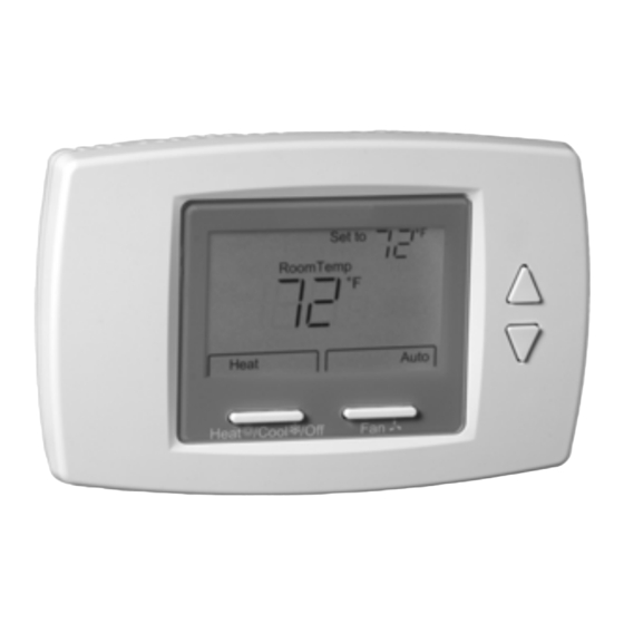
TB6575/TB8575 Digital Fan Coil
Thermostats
PRODUCT DESCRIPTION
The TB6575 and TB8575 are a family of Digital Fan Coil
thermostats for residential and commercial applications
such as hotels, condominiums, school classrooms, etc.
Three models are available for your application:
• TB6575A1000 - 2-pipe or 4-pipe with seasonal/
manual/automatic heat/cool changeover; 120/240
Vac.
• TB6575B1000 - 2-pipe only with seasonal or manual
heat/cool changeover; 120/240 Vac.
• TB8575A1000 - 2-pipe or 4-pipe with seasonal heat/
cool changeover; 24Vac.
All three models are suitable for multiple applications.
Changes in output wiring and external links between
wiring terminals allow you to configure the thermostat for
the appropriate application.
The applications that are available are:
• Heating or Cooling only
• Two pipes: Heat or Cool with Manual Changeover
• Two pipes: Heat or Cool with Seasonal Changeover
(requires optional pipe sensor)
• Two pipes: Heat or Cool with Auxiliary Heat and
Manual or Seasonal Changeover (requires optional
pipe sensor)
• Four pipes: Mixed Manual and Auto Changeover
• Four pipes: Manual Changeover
• Four pipes: Auto Changeover
The fan is controlled from the thermostat. The Low,
Medium, High, or Auto fan settings are easily made with
a press of a key.
Valves and auxiliary electric heaters can be controlled
using a relay or contactor controlled by the system
switch.
INSTALLATION INSTRUCTIONS
FEATURES
• Simple, intuitive user interface.
• Pre-installed lead wires for fast installation
(TB6575A and TB6575B models only)
• Backlight display permits easy viewing in any
light.
• Four buttons allow manual control of system
operation, fan speed, and temperature setpoint
adjustment.
• Digital display of ambient temperature, setpoint,
heating or cooling mode, fan status, and remote
setback
• Proportional plus Integral (P+I) control algorithm
for precision temperature regulation.
• Single Setpoint and Heat/Cool setpoint methods
for 4-pipe auto changeover.
• Adjustable maximum heating and minimum
cooling setpoint limits using range stops.
• EEPROM permanently retains user settings,
including setpoints, during power loss (no
batteries required).
• Selectable °C or °F display via Setup button on
thermostat.
• Displayable pipe sensor temperature readout to
aid in troubleshooting.
• Selectable to allow the fan motor to always begin
on high speed to ensure sufficient torque at
startup.
• Option to wire a remote indoor temperature
sensor.
• Freeze protect algorithm turns on heat when
needed.
• Economy Setback options via dry contact or
Activity Sensing
• Advanced fan control with VersaSpeed™ fan ramp
algorithm and Auto Fan Reset
Product Description ...................................................
Features ....................................................................
Specifications ............................................................
Installation .................................................................
Setup ......................................................................... 10
Operation ................................................................... 14
Troubleshooting ......................................................... 17
Contents
Place Bar Code Here
62-0311-05
1
1
2
3
Advertisement
Table of Contents

Related Manuals for Honeywell TB6575B1000/U - SuitePro Digital Fan Coil Stat


Summary of Contents for Honeywell TB6575B1000/U - SuitePro Digital Fan Coil Stat
-
Page 1: Table Of Contents
TB6575/TB8575 Digital Fan Coil Thermostats INSTALLATION INSTRUCTIONS FEATURES • Simple, intuitive user interface. • Pre-installed lead wires for fast installation (TB6575A and TB6575B models only) • Backlight display permits easy viewing in any light. • Four buttons allow manual control of system operation, fan speed, and temperature setpoint adjustment. -
Page 2: Specifications
TB6575/TB8575 DIGITAL FAN COIL THERMOSTATS SPECIFICATIONS Enclosure: Plastic (cover, sub-base, and optional adap- tor plate) Supply Voltages: Junction Box Mounting: Direct mounting on a horizontal TB6575A1000 and TB6575B1000: single gang NEMA 2 x 4 in. surface mount electrical box, • 120 Vac ±10% at 50/60Hz or on 4 x 4 in. -
Page 3: Installation
TB6575/TB8575 DIGITAL FAN COIL THERMOSTATS The five relays are wired via terminals W, Y, Gh, Gm, and Gl. Relay 1 controls Heat open (W) or Cool open (Y). Relay 2 controls Cool open or Electrical heater output (Y/A). Relays 3, 4, and 5 control the High, Medium, and Low fan speeds respectively (Gh, Gm, and Gl). - Page 4 TB6575/TB8575 DIGITAL FAN COIL THERMOSTATS (1) Attach the supply wires directly to the termi- Attach the sub-base to the junction box using nals on the sub-base. See Table 3 on the screws provided. page 5 for terminal identification. 4. Thoroughly check the wiring to the sub-base before (2) Push the supply wires back into the junction finally mounting the thermostat on the wall.
- Page 5 TB6575/TB8575 DIGITAL FAN COIL THERMOSTATS • N: Line voltage ground (120/240 Vac) • Sc: Ground (required if remote sensor, pipe sensor, and/or remote setback are connected) • Ps: Pipe sensor (optional) • W/Y: W = Heating; Y = Cooling (2 pipe only) •...
- Page 6 TB6575/TB8575 DIGITAL FAN COIL THERMOSTATS Accessory Wiring NOTE: For complete wiring instructions, please follow the installation instructions provided with the remote sensor. Remote Pipe Sensor Wiring Sensor Wiring for Temperature The remote pipe sensor is used for 2 pipes auto and 2 pipes heat and cool with auxiliary heat changeover.
- Page 7 TB6575/TB8575 DIGITAL FAN COIL THERMOSTATS Thermostat Wiring Diagrams The figures in this section illustrate typical wiring for: L (HOT) • TB6575A1000 and TB6575B1000 fan coil thermostats, VALVE which are 120/240 Vac powered. Refer to Fig. 7–Fig. 13, beginning on page 7. •...
- Page 8 TB6575/TB8575 DIGITAL FAN COIL THERMOSTATS 24 Vac Wiring Diagrams (TB8575) For the TB8575A1000 model, a 24 Vac Class 2 NEMA L (HOT) rated transformer must be used. HEAT VALVE COOL VALVE HEAT VALVE REMOTE SENSOR (HOT) 24 VAC REMOTE SETBACK REMOTE SENSOR REMOTE SETBACK REMOVE PRE-WIRED WIRE FROM TERMINAL 5 (MID FAN SPEED).
-
Page 9: Removing The Thermostat
TB6575/TB8575 DIGITAL FAN COIL THERMOSTATS VALVE HEAT VALVE COOL VALVE (HOT) 24 VAC (HOT) 24 VAC REMOTE SENSOR REMOTE SENSOR REMOTE SETBACK REMOTE SETBACK PIPE SENSOR POWER SUPPLY. PROVIDE DISCONNECT MEANS AND REMOVE PRE-WIRED WIRE FROM TERMINAL 5 (MID FAN SPEED). OVERLOAD PROTECTION AS REQUIRED. -
Page 10: Setup
TB6575/TB8575 DIGITAL FAN COIL THERMOSTATS UP AND DOWN ARROW BUTTONS ºF Set to RoomTemp ºF Heat On Fan On Heat Auto System M27586 M27592 SYSTEM BUTTON BUTTON Fig. 21. Removing the thermostat. Fig. 23. LCD display showing default screen. SETUP Power-up At power-up, the thermostat’s LCD shows all display The thermostat provides an LCD display, two buttons... - Page 11 TB6575/TB8575 DIGITAL FAN COIL THERMOSTATS Setup M27585 Fig. 24. Installer Setup (ISU) mode screen. Table 4. Installer Setup (ISU) Codes and Options. Option Option Description (Default value shown in Code Code Description Value Bold) Notes Line Voltage 120 Vac power supply (Default) Selection 240 Vac power supply System Type...
- Page 12 TB6575/TB8575 DIGITAL FAN COIL THERMOSTATS Table 4. Installer Setup (ISU) Codes and Options. (Continued) Option Option Description (Default value shown in Code Code Description Value Bold) Notes 8.5 Fan Speed at motor Provide full power when fan motor starts – High speed start up start up always starts in high fan speed (Default)
- Page 13 TB6575/TB8575 DIGITAL FAN COIL THERMOSTATS Table 4. Installer Setup (ISU) Codes and Options. (Continued) Option Option Description (Default value shown in Code Code Description Value Bold) Notes Remote Setback Disabled Hotel card enabled N.O. for unoccupied mode with 1 second software delay going from UnOccupied to Occupied;...
-
Page 14: Operation
TB6575/TB8575 DIGITAL FAN COIL THERMOSTATS OPERATION NOTE: Exiting Installer Test Mode is the same as the method for entering test mode, PROPORTIONAL + INTEGRAL (P+I) CONTROL Like a mechanical thermostat, the fan coil thermostats Test have On/Off control output. However, this output is regulated by a P+I algorithm, enabling the thermostat to control closer to setpoint than conventional thermostats. -
Page 15: Fan Modes
TB6575/TB8575 DIGITAL FAN COIL THERMOSTATS Fig. 26 illustrates the relationship between setpoints, AUTO FAN RESET (ISU CODE #24) Remote Setback, and deadband for auto changeover with If Auto Fan Reset is enabled, and a constant fan speed is heat and cool setpoints. selected, the thermostat resets the fan to Auto. - Page 16 TB6575/TB8575 DIGITAL FAN COIL THERMOSTATS Operation: 4 PIPES AUTO CHANGEOVER After exiting the installer setup, the thermostat will perform Single Set Point Method a 5 minute purge. During this time, the valve (W/Y) will energize and the fan and auxiliary heat (Y/A) will be de- In 4 pipe auto changeover with a single setpoint, the energized.
-
Page 17: Troubleshooting
TB6575/TB8575 DIGITAL FAN COIL THERMOSTATS TROUBLESHOOTING Table 8 provides troubleshooting information. Table 8. Troubleshooting. Symptom Possible Cause Action Display does not Thermostat is not being For TB6575A/B, check for 120/240 Vac between L and N. come on. powered. For TB8575A, check for 24 Vac between R and C. Temperature settings The upper or lower Check the temperature setpoints for heating and cooling (Installer... - Page 18 TB6575/TB8575 DIGITAL FAN COIL THERMOSTATS Table 8. Troubleshooting. (Continued) Symptom Possible Cause Action Cooling does not turn Cooling equipment failure. For TB6575A/B: on (Cool On is solid in 1. Check for 120/240 Vac at the equipment between power and the display). common, (terminals L and N).
- Page 19 TB6575/TB8575 DIGITAL FAN COIL THERMOSTATS Table 8. Troubleshooting. (Continued) Symptom Possible Cause Action Activity Sensing does All buttons are locked. Make sure keypad lockout is disabled. Set ISU code #18, value = not exit when button pressed Freeze Protection System Type is set to Freeze protection is not activated when system type is Cool (ISU does not activate Cool.
- Page 20 Automation and Control Solutions Honeywell International Inc. 1985 Douglas Drive North Golden Valley, MN 55422 Honeywell Limited-Honeywell Limitée 35 Dynamic Drive ® U.S. Registered Trademark Toronto, Ontario M1V 4Z9 © 2010 Honeywell International Inc. 62-0311—05 M.S. Rev. 10-10 customer.honeywell.com Printed in U.S.A.