Intel BLKDH61WWB3 Product Manual
Product guide
Hide thumbs
Also See for BLKDH61WWB3:
- Technical product specification (86 pages) ,
- Specification (7 pages) ,
- Quick reference manual (1 page)
Table of Contents
Advertisement
Advertisement
Table of Contents

Related Manuals for Intel BLKDH61WWB3


Summary of Contents for Intel BLKDH61WWB3
- Page 1 Intel® Desktop Board DH61WW Product Guide Order Number: G23562-003...
-
Page 2: Revision History
WARRANTIES RELATING TO FITNESS FOR A PARTICULAR PURPOSE, MERCHANTABILITY, OR INFRINGEMENT OF ANY PATENT, COPYRIGHT OR OTHER INTELLECTUAL PROPERTY RIGHT. Intel products are not intended for use in medical, life saving, or life sustaining applications. Intel may make changes to specifications and product descriptions at any time, without notice. -
Page 3: Intended Audience
The suitability of this product for other PC or embedded non-PC applications or other environments, such as medical, industrial, alarm systems, test equipment, etc. may not be supported without further evaluation by Intel. Document Organization The chapters in this Product Guide are arranged as follows:... - Page 4 Intel Desktop Board DH61WW Product Guide Terminology The table below gives descriptions of some common terms used in the product guide. Term Description Gigabyte (1,073,741,824 bytes) Gigahertz (one billion hertz) Kilobyte (1024 bytes) Megabyte (1,048,576 bytes) Megabit (1,048,576 bits) Megahertz (one million hertz)
-
Page 5: Table Of Contents
1 Desktop Board Features Supported Operating Systems ................11 Desktop Board Components ................. 12 Processor ......................14 ® Intel H61 Express Chipset ................. 15 Main Memory..................... 15 Graphics Subsystem ................... 16 Integrated Graphics ..................16 Analog Display (VGA) ................16 PCI Express* x16 Graphics ................ - Page 6 Express BIOS Update Utility ......... 59 Updating the BIOS Using the F7 Function Key ............60 ® Updating the BIOS with the ISO Image BIOS Update File or the Intel Flash Memory Update Utility ................... 61 Obtaining the BIOS Update File ..............61 Updating the BIOS with the Intel Flash Memory Update Utility ......
-
Page 7: Lift The Load Plate ......................................................................................... 32 8. Remove The Processor From The Protective Cover .............................................. 33
20. Location of the Chassis Fan Header ..............49 21. Connecting Power Supply Cables ..............50 22. Location of the BIOS Configuration Jumper Block ..........51 23. Removing the Battery ................... 58 24. Intel Desktop Board DH61WW China RoHS Material Self Declaration Table .... 72... - Page 8 2. Intel Desktop Board DH61WW Components ............13 3. LAN Status LEDs States ................. 18 4. Front Panel Audio Signal Names for Intel HD Audio ..........44 5. Front Panel Audio Header Signal Names for AC ’97 Audio ........44 6.
-
Page 9: Desktop Board Features
Intel High Definition Audio (Intel HD Audio): • Realtek* ALC892 audio codec • Front panel audio header (Intel HD Audio and AC ’97 Audio support) • S/PDIF audio header Expansion • One PCI Express 2.0 x16 add-in card connector Capabilities •... - Page 10 ― Two USB 2.0 front panel ports are implemented through a dual- port internal header • Four SATA 3 Gb/s ports through the Intel H61 Express Chipset • One serial port header • One parallel port back panel connector •...
-
Page 11: Supported Operating Systems
Desktop Board Features Supported Operating Systems The Desktop Board supports the following operating systems: • Microsoft Windows* 7 Ultimate 64-bit edition • Microsoft Windows 7 Ultimate 32-bit edition • Microsoft Windows 7 Professional 64-bit edition • Microsoft Windows 7 Professional 32-bit edition •... -
Page 12: Desktop Board Components
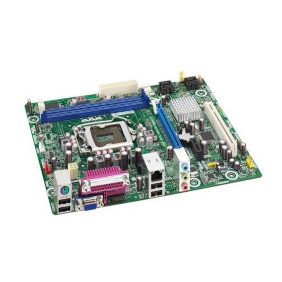
Intel Desktop Board DH61WW Product Guide Desktop Board Components Figure 1 shows the approximate location of the major components on Intel Desktop Board DH61WW. Figure 1. Intel Desktop Board DH61WW Components... -
Page 13: Intel Desktop Board Dh61Ww Components
Desktop Board Features Table 2. Intel Desktop Board DH61WW Components Label Description Conventional PCI bus add-in card connector Chassis intrusion header S/PDIF header PCI Express 2.0 x1 add-in card connector Battery PCI Express 2.0 x16 add-in card connector Back panel connectors... -
Page 14: Processor
Desktop Board may result in damage to the board, or the system may not function properly. Intel Desktop Board DH61WW supports Intel Core i7, Intel Core i5, Intel Core i3, and Intel Pentium processors in the LGA1155 package. Processors are not included with the Desktop Board and must be purchased separately. -
Page 15: Intel H61 Express Chipset
Intel H61 Express Chipset The Intel H61 Express Chipset, consisting of the Intel H61 Platform Controller Hub (PCH), provides interfaces to the processor and the USB, SATA, LPC, audio, network, display, and PCI Express interfaces. The PCH is a centralized controller for the board’s I/O paths. -
Page 16: Graphics Subsystem
DVI-D connector status. PCI Express* x16 Graphics Intel Core i7, Intel Core i5, Intel Core i3, and Intel Pentium processors in an LGA1155 package support discrete add-in graphics cards via the PCI Express 2.0 x16 add-in card connector. -
Page 17: Lan Subsystem
The onboard S/PDIF header allows connection to coaxial or optical adapters for digital audio output. The back panel audio connectors are configurable through the audio device drivers. Audio software and drivers are available from http://downloadcenter.intel.com/. LAN Subsystem The LAN subsystem includes: •... -
Page 18: Usb Support
SATA Support The board provides four SATA 3.0 Gb/s channels, through the PCH, which support one device per channel. Expandability Intel Desktop Board DH61WW provides the following expansion capability: • One PCI Express 2.0 x16 interface • One PCI Express 2.0 x1 interface •... -
Page 19: Bios
Desktop Board Features BIOS The BIOS provides the Power-On Self-Test (POST), the BIOS Setup program, and the PCI/PCI Express and SATA auto-configuration utilities. The BIOS is stored in the Serial Peripheral Interface (SPI) Flash memory device. The BIOS can be updated by following the instructions in Chapter 3 starting on page 59. -
Page 20: Trusted Platform Module (Tpm) Support
Fan Speed Control and Hardware Monitoring The features of the hardware monitoring and fan speed control include: • Thermal sensors in the processor and the Intel PCH, as well as near the processor voltage regulators and system memory • Monitoring of system voltages to detect levels above or below acceptable values •... -
Page 21: Hardware Support
Desktop Board Features Hardware Support Power Connectors ATX12V-compliant power supplies can turn off the computer power through system control. When an ACPI-enabled computer receives the correct command, the power supply removes all non-standby voltages. When resuming from an AC power failure, the computer returns to the power state it was in before power was interrupted (either on or off). - Page 22 Intel Desktop Board DH61WW Product Guide Instantly Available PC Technology CAUTION For Instantly Available PC technology, the 5 V standby line for the power supply must be capable of delivering adequate +5 V standby current. Failure to provide adequate standby current when using this feature can damage the power supply and/or effect ACPI S3 sleep state functionality.
- Page 23 For example, when this green LED is lit, standby power is still present at the memory module sockets and the PCI connector. Figure 3. Location of the Standby Power Indicator For more information on standby current requirements for the Desktop Board, refer to the Technical Product Specification at http://www.intel.com/support/motherboards/desktop/.
- Page 24 Intel Desktop Board DH61WW Product Guide Wake from USB NOTE Wake from USB requires the use of a USB peripheral that supports Wake from USB and an operating system that supports Wake from USB. USB bus activity wakes the computer from an ACPI S3 state.
-
Page 25: Onboard Speaker
Desktop Board Features Onboard Speaker A speaker is mounted on the Desktop Board. The speaker provides audible error code (beep code) information during the Power-On Self-Test (POST). Refer to Appendix A for a description of the beep codes that may be generated during the POST. Real-Time Clock Subsystem A coin-cell battery (CR2032) powers the real-time clock and CMOS memory. - Page 26 Intel Desktop Board DH61WW Product Guide...
-
Page 27: Installing And Replacing Desktop Board Components
2 Installing and Replacing Desktop Board Components This chapter tells you how to: • Install the I/O shield • Install and remove the Desktop Board • Install and remove a processor • Install and remove memory • Install and remove a PCI Express x16 card •... -
Page 28: Installation Precautions
Intel Desktop Board DH61WW Product Guide Installation Precautions When you install and test the Intel Desktop Board, observe all warnings and cautions in the installation instructions. To avoid injury, be careful of: • Sharp pins on connectors • Sharp pins on printed circuit assemblies •... -
Page 29: Installing The I/O Shield
Installing and Replacing Desktop Board Components Installing the I/O Shield The Desktop Board comes with an I/O shield. When installed in the chassis, the shield blocks radio frequency transmissions, protects internal components from dust and foreign objects, and promotes correct airflow within the chassis. Install the I/O shield before installing the Desktop Board in the chassis. -
Page 30: Installing And Removing The Desktop Board
Refer to your chassis manual for instructions on installing and removing the Desktop Board. Figure 5 shows the location of the mounting screw holes for Intel Desktop Board DH61WW. Figure 5. Intel Desktop Board DH61WW Mounting Screw Hole Locations... -
Page 31: Installing And Removing A Processor
Installing and Replacing Desktop Board Components Installing and Removing a Processor Instructions on how to install the processor on the Desktop Board are given below. Installing a Processor CAUTION Before installing or removing a processor, make sure the AC power has been removed by unplugging the power cord from the computer;... - Page 32 Intel Desktop Board DH61WW Product Guide 3. Rotate the socket lever to lift the load plate away from the socket (Figure 7, A). Make sure that the load plate is in the fully open position (Figure 7, B) while being careful not to damage adjacent components.
-
Page 33: Remove The Processor From The Protective Cover
Installing and Replacing Desktop Board Components 4. Remove the processor from its protective cover. Hold the processor only at the edges, being careful not to touch the bottom of the processor (see Figure 8). NOTE Do not discard the processor cover. Always replace the processor cover if you remove the processor from the socket. - Page 34 Intel Desktop Board DH61WW Product Guide 6. Carefully lower the socket lever (Figure 10, A) while making sure that the front edge of the load plate slides under the shoulder screw cap as the lever is lowered. Latch the socket lever under the load plate tab (Figure 10, C, D). The socket cover (Figure 10, B) will pop off as shown.
-
Page 35: Installing A Processor Fan Heat Sink
Installing and Replacing Desktop Board Components Installing a Processor Fan Heat Sink Intel Desktop Board DH61WW has mounting holes for a processor fan heat sink. For instructions on how to attach the processor fan heat sink to the Desktop Board, refer to the boxed processor manual or boxed thermal solution manual. -
Page 36: Installing And Removing System Memory
Installing and Removing System Memory NOTE To be fully compliant with all applicable Intel SDRAM memory specifications, the board requires DIMMs that support the Serial Presence Detect (SPD) data structure. The desktop board has two 240-pin DDR3 DIMM sockets providing Channel A and Channel B. -
Page 37: Installing Dimms
Installing and Replacing Desktop Board Components Installing DIMMs To make sure you have the correct DIMM, place it on the illustration of the DDR3 DIMM in Figure 13. All the notches should match with the DDR3 DIMM. Figure 13. Use DDR3 DIMMs... - Page 38 Intel Desktop Board DH61WW Product Guide To install a DIMM, follow these steps: 1. Observe the precautions in "Before You Begin" on page 27. 2. Turn off all peripheral devices connected to the computer. Turn off the computer and disconnect the AC power cord.
-
Page 39: Removing Dimms
Installing and Replacing Desktop Board Components Removing DIMMs To remove a DIMM, follow these steps: 1. Observe the precautions in "Before You Begin" on page 27. 2. Turn off all peripheral devices connected to the computer. Turn off the computer. 3. -
Page 40: Installing A Pci Express X16 Graphics Card
Intel Desktop Board DH61WW Product Guide Follow these instructions to install a PCI Express x16 graphics card: 1. Observe the precautions in "Before You Begin" on page 27. 2. Place the card in the PCI Express x16 connector (Figure 15, A) and press down on the card until it is completely seated in the connector and the card retention notch on the card snaps into place around the retention mechanism pin on the connector. -
Page 41: Removing A Pci Express X16 Graphics Card
Installing and Replacing Desktop Board Components Removing a PCI Express x16 Graphics Card Follow these instructions to remove a PCI Express x16 graphics card from a connector: 1. Observe the precautions in "Before You Begin" on page 27. 2. Disconnect the monitor cable from the graphics card back panel connector. 3. -
Page 42: Connecting Serial Ata (Sata) Cables
Intel Desktop Board DH61WW Product Guide Connecting Serial ATA (SATA) Cables SATA cables support the Serial ATA protocol. Each cable can be used to connect one internal SATA drive to the Desktop Board. For correct cable function: 1. Observe the precautions in “Before You Begin” on page 27. -
Page 43: Connecting To The Internal Headers
Connecting to the Internal Headers Before connecting cables to any of the internal headers, observe the precautions in “Before You Begin” on page 27. Figure 18 shows the location of the internal headers and connectors on Intel Desktop Board DH61WW. Figure 18. Internal Headers... -
Page 44: Front Panel Audio Header
Intel Desktop Board DH61WW Product Guide Front Panel Audio Header The front panel audio header shown in Figure 18, A supports both Intel High Definition Audio and AC ’97 Audio. Table 4 shows the pin assignments and signal names for HD Audio and Table 5 shows the pin assignments and signal names for AC ’97 Audio. -
Page 45: Chassis Intrusion Header
Installing and Replacing Desktop Board Components Chassis Intrusion Header Figure 18, C shows the location of the chassis intrusion header. This header can be connected to a mechanical switch on the chassis to detect if the chassis cover is removed. This switch should be in the open position when the chassis cover is installed and closed when the cover is removed. -
Page 46: Front Panel Header
Intel Desktop Board DH61WW Product Guide Front Panel Header Figure 18, E shows the location of the front panel header. Table 9 shows the pin assignments and signal names for the front panel header. Table 9. Front Panel Header Signal Names... -
Page 47: Front Panel Usb 2.0 Header
Installing and Replacing Desktop Board Components Front Panel USB 2.0 Header Figure 18, G shows the location of the front panel USB 2.0 header and Table 11 shows the pin assignments and signal names. Table 11. Front Panel USB 2.0 Header Signal Names Signal Name Signal Name Power (+5 V) -
Page 48: Connecting To The Audio System
Intel Desktop Board DH61WW Product Guide Connecting to the Audio System ® After installing the Realtek audio driver from the Intel Express Installer DVD-ROM, the multi-channel audio feature can be enabled. Figure 19 shows the back panel audio connectors. The default connector assignments are shown in the table. -
Page 49: Connecting Chassis Fan And Power Supply Cables
Installing and Replacing Desktop Board Components Connecting Chassis Fan and Power Supply Cables Connecting a Chassis Fan Cable Connect chassis fan cables to the chassis fan header on the Desktop Board. Figure 20 shows the location of the chassis fan header. Figure 20. -
Page 50: Connecting Power Supply Cables
Intel Desktop Board DH61WW Product Guide Connecting Power Supply Cables CAUTION Failure to use an appropriate power supply and/or not connecting the 12 V power connector (Figure 21, A) to the Desktop Board may result in damage to the board or the system may not function properly. -
Page 51: Setting The Bios Configuration Jumper
Installing and Replacing Desktop Board Components Setting the BIOS Configuration Jumper NOTE Always turn off the power to the computer before moving the jumper. Moving the jumper with the power on may result in unreliable computer operation. Figure 22 shows the location of the Desktop Board’s BIOS configuration jumper block. Figure 22. -
Page 52: Clearing Passwords In The Bios Setup Program
Intel Desktop Board DH61WW Product Guide The three-pin BIOS jumper block enables board configuration to be done in the BIOS Setup program. Table 12 shows the jumper settings for the BIOS Setup program modes. Table 12. Jumper Settings for the BIOS Setup Program Modes... -
Page 53: Replacing The Battery
Installing and Replacing Desktop Board Components 8. Use the arrow keys to select Clear Passwords. Press <Enter> and Setup displays a pop-up screen requesting that you confirm clearing the password. Select Yes and press <Enter>. Setup displays the maintenance menu again. 9. - Page 54 Intel Desktop Board DH61WW Product Guide OBS! Det kan oppstå eksplosjonsfare hvis batteriet skiftes ut med feil type. Brukte batterier bør kastes i henhold til gjeldende miljølovgivning. VIKTIGT! Risk för explosion om batteriet ersätts med felaktig batterityp. Batterier ska kasseras enligt de lokala miljövårdsbestämmelserna.
- Page 55 Installing and Replacing Desktop Board Components UPOZORNÌNÍ V případě výměny baterie za nesprávný druh může dojít k výbuchu. Je-li to možné, baterie by měly být recyklovány. Baterie je třeba zlikvidovat v souladu s místními předpisy o životním prostředí. Προσοχή Υπάρχει κίνδυνος για έκρηξη σε περίπτωση που η μπαταρία αντικατασταθεί από μία λανθασμένου...
- Page 56 Intel Desktop Board DH61WW Product Guide UPOZORNENIE Ak batériu vymeníte za nesprávny typ, hrozí nebezpečenstvo jej výbuchu. Batérie by sa mali podľa možnosti vždy recyklovať. Likvidácia použitých batérií sa musí vykonávať v súlade s miestnymi predpismi na ochranu životného prostredia.
- Page 57 Installing and Replacing Desktop Board Components...
- Page 58 Intel Desktop Board DH61WW Product Guide To replace the battery, follow these steps: 1. Observe the precautions in "Before You Begin" (see page 27). 2. Turn off all peripheral devices connected to the computer. Disconnect the computer’s power cord from the AC power source (wall outlet or power adapter).
-
Page 59: Updating The Bios
Power-On Self-Test (POST) memory test begins and before the operating system boot begins. This chapter tells you how to update the BIOS by either using the Intel Express BIOS Update utility or the Intel Flash Memory Update Utility, and how to recover the BIOS ®... -
Page 60: Updating The Bios Using The F7 Function Key
Intel Desktop Board DH61WW Product Guide Updating the BIOS Using the F7 Function Key To use this BIOS update method: 1. Download and save the Recovery BIOS (.BIO) file to a temporary directory. 2. Copy the .BIO file to a USB thumb drive. The USB thumb drive does not need to be bootable, only formatted. -
Page 61: Updating The Bios With The Iso Image Bios Update File Or The Intel Flash Memory Update Utility
Update File or the Intel Flash Memory Update Utility You can use the information in this section to update the BIOS using either the Intel Flash Memory Update Utility or the ISO Image BIOS update file. Obtaining the BIOS Update File You can update to a new version of the BIOS by using the ISO Image BIOS update file (recommended), or Intel Flash Memory BIOS update file. -
Page 62: Updating The Bios With The Iso Image Bios Update File
Enter key. The system will boot from the hard drive if no key is pressed within 15 seconds. 5. At the "Welcome to the Intel Desktop Board BIOS Upgrade CD-ROM" page, press any key to confirm the BIOS upgrade operation. -
Page 63: Recovering The Bios
CD-R with the .BIO file in the root directory will be required. You can obtain the Recovery BIOS Update file through your computer supplier or by navigating to the Intel Desktop Board DH61WW page on the Intel World Wide Web site Download Center at http://downloadcenter.intel.com. - Page 64 Intel Desktop Board DH61WW Product Guide...
-
Page 65: A Error Messages And Indicators
A Error Messages and Indicators Intel Desktop Board DH61WW reports POST errors in two ways: • By sounding a beep code and blinking the front panel power LED • By displaying an error message on the monitor BIOS Error Codes Whenever a recoverable error occurs during POST, the BIOS causes the board’s... -
Page 66: Front-Panel Power Led Blink Codes
Intel Desktop Board DH61WW Product Guide Table 14. Front-panel Power LED Blink Codes Type Pattern Note F2 Setup/F10 Boot None Menu Prompt BIOS update in Off when the update begins, then on for progress 0.5 seconds, then off for 0.5 seconds. The pattern repeats until the BIOS update is complete. -
Page 67: B Regulatory Compliance
Product Ecology statements • Electromagnetic Compatibility (EMC) regulations • Product certifications Safety Standards Intel Desktop Board DH61WW complies with the safety standards stated in Table 16 when correctly installed in a compatible host system. Table 16. Safety Standards Regulation Title CSA/UL 60950-1 Information Technology Equipment –... -
Page 68: European Union Declaration Of Conformity Statement
Intel Desktop Board DH61WW Product Guide European Union Declaration of Conformity Statement We, Intel Corporation, declare under our sole responsibility that the product Intel ® Desktop Board DH61WW is in conformity with all applicable essential requirements necessary for CE marking, following the provisions of the European Council Directives 2004/108/EC (EMC Directive), 2006/95/EC (Low Voltage Directive), and 2002/95/EC (ROHS Directive). -
Page 69: Product Ecology Statements
The following information is provided to address worldwide product ecology concerns and regulations. Recycling Considerations As part of its commitment to environmental responsibility, Intel has implemented the ® Intel Product Recycling Program to allow retail consumers of Intel’s branded products to return used products to selected locations for proper recycling. - Page 70 Français Dans le cadre de son engagement pour la protection de l'environnement, Intel a mis en œuvre le programme Intel Product Recycling Program (Programme de recyclage des produits Intel) pour permettre aux consommateurs de produits Intel de recycler les produits usés en les retournant à...
- Page 71 Regulatory Compliance Portuguese Como parte deste compromisso com o respeito ao ambiente, a Intel implementou o Programa de Reciclagem de Produtos para que os consumidores finais possam enviar produtos Intel usados para locais selecionados, onde esses produtos são reciclados de maneira adequada.
-
Page 72: China Rohs
The China Ministry of Information Industry (MII) stipulates that a material Self Declaration Table (SDT) must be included in a product’s user documentation. The SDT for Intel Desktop Board DH61WW is shown in Figure 24. Figure 24. Intel Desktop Board DH61WW China RoHS Material... -
Page 73: Emc Regulations
Regulatory Compliance EMC Regulations Intel Desktop Board DH61WW complies with the EMC regulations stated in Table 17 when correctly installed in a compatible host system. Table 17. EMC Regulations Regulation Title FCC 47 CFR Part 15, Title 47 of the Code of Federal Regulations, Part 15, Subpart B, Subpart B Radio Frequency Devices. -
Page 74: Canadian Department Of Communications Compliance Statement
• Consult the dealer or an experienced radio/TV technician for help. Any changes or modifications to the equipment not expressly approved by Intel Corporation could void the user’s authority to operate the equipment. Tested to comply with FCC standards for home or office use. -
Page 75: Korea Class B Statement
Regulatory Compliance Korea Class B Statement Korea Class B Statement translation: This equipment is for home use, and has acquired electromagnetic conformity registration, so it can be used not only in residential areas, but also other areas. Ensure Electromagnetic Compatibility (EMC) Compliance Before computer integration, make sure that the power supply and other modules or peripherals, as applicable, have passed Class B EMC testing and are marked... -
Page 76: Product Certifications
(solder side). China RoHS/Environmentally Friendly Use Period Logo: This is an example of the symbol used on Intel Desktop Boards and associated collateral. The color of the mark may vary depending upon the application. The Environmental Friendly Usage Period (EFUP) for... -
Page 77: Chassis- And Component-Level Certifications
Compliance The US Department of Energy and the US Environmental Protection Agency have continually revised the ENERGY STAR requirements. Intel has worked directly with these two governmental agencies in the definition of the new requirements. This Desktop Board meets the ENERGY STAR Program for Computers: Version 5.0 Category A requirements. - Page 78 Intel Desktop Board DH61WW Product Guide...