Table of Contents
Advertisement
Quick Links
Intel® Desktop Board
D946GZIS
Technical Product Specification
®
The Intel
Desktop Board D946GZIS may contain design defects or errors known as errata that may cause the product to deviate from published specifications. Current
characterized errata are documented in the Intel Desktop Board D946GZIS Specification Update.
September 2006
Order Number: D56025-002US
Advertisement
Table of Contents

Related Manuals for Intel BLKD946GZISSL - CONROE LGA775 1066 800FSB DR2 A/V Lan SATA mATX 10Pack ACTIVE Motherboard


Summary of Contents for Intel BLKD946GZISSL - CONROE LGA775 1066 800FSB DR2 A/V Lan SATA mATX 10Pack ACTIVE Motherboard
- Page 1 Order Number: D56025-002US ® The Intel Desktop Board D946GZIS may contain design defects or errors known as errata that may cause the product to deviate from published specifications. Current characterized errata are documented in the Intel Desktop Board D946GZIS Specification Update.
-
Page 2: Revision History
Current characterized errata are available on request. Contact your local Intel sales office or your distributor to obtain the latest specifications before placing your product order. -
Page 3: Intended Audience
Preface This Technical Product Specification (TPS) specifies the board layout, components, ® connectors, power and environmental requirements, and the BIOS for the Intel Desktop Board D946GZIS. It describes the standard product and available manufacturing options. Intended Audience The TPS is intended to provide detailed, technical information about the Desktop Board D946GZIS and its components to the vendors, system integrators, and other engineers and technicians who need this level of information. - Page 4 Intel Desktop Board D946GZIS Technical Product Specification Other Common Notation Used after a signal name to identify an active-low signal (such as USBP0#) Gigabyte (1,073,741,824 bytes) GB/sec Gigabytes per second Gbit Gigabit (1,073,741,824 bits) Kilobyte (1024 bytes) Kbit Kilobit (1024 bits)
-
Page 5: Table Of Contents
1.4 System Memory ................16 1.4.1 Memory Configurations ............18 1.5 Intel ® 946GZ Express Chipset ............21 1.5.1 Intel 946GZ Graphics Subsystem ..........21 1.5.2 USB ................... 23 1.5.3 Serial ATA Interfaces ............24 1.5.4 Parallel IDE Interface ............25 1.5.5... - Page 6 Intel Desktop Board D946GZIS Technical Product Specification 2.6 PCI Interrupt Routing Map ..............49 2.7 Connectors and Headers..............50 2.7.1 Back Panel Connectors ............51 2.7.2 Component-side Connectors and Headers ........ 52 2.8 Jumper Block .................. 60 2.9 Mechanical Considerations ..............61 2.9.1...
- Page 7 Contents 4.3 BIOS Error Messages ............... 83 4.4 Port 80h POST Codes ............... 84 Figures Major Board Components..............12 Block Diagram ................14 Memory Channel and DIMM Configuration ........... 18 Dual Channel (Interleaved) Mode Configuration with Two DIMMs.... 19 Single Channel (Asymmetric) Mode Configuration with One DIMM ..20 Single Channel (Asymmetric) Mode Configuration with Two DIMMs ..
- Page 8 Intel Desktop Board D946GZIS Technical Product Specification 20. Serial ATA Connectors ..............54 21. High Definition Audio Link Header ............54 22. Processor Core Power Connector............56 23. Main Power Connector..............56 24. Front Panel Header ................57 25. States for a One-Color Power LED ............58 26.
- Page 9 1.1 Overview..................10 1.2 Online Support................15 1.3 Processor ..................15 1.4 System Memory ................16 ® 1.5 Intel 946GZ Express Chipset ............21 1.6 Legacy I/O Controller ............... 30 1.7 Audio Subsystem................31 1.8 LAN Subsystem ................33 1.9 Hardware Management Subsystem ............ 34...
-
Page 10: Overview
Intel Desktop Board D946GZIS Technical Product Specification Overview 1.1.1 Feature Summary Table 1 summarizes the major features of the Desktop Board D946GZIS. Table 1. Feature Summary Form Factor microATX (9.60 inches by 9.60 inches [243.84 millimeters by 243.84 millimeters]) Processor Support for the following: ®... - Page 11 Product Description Table 1. Feature Summary (continued) • One PCI Express x16 bus add-in card connector Expansion Capabilities • One PCI Express x1 bus add-in card connector • Two PCI Conventional* bus connectors • Voltage sense to detect out of range power supply voltages Hardware Monitor Subsystem •...
-
Page 12: Board Layout
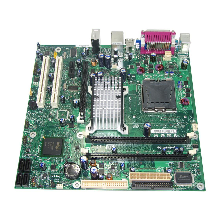
Intel Desktop Board D946GZIS Technical Product Specification 1.1.2 Board Layout Figure 1 shows the location of the major components. OM18377 Figure 1. Major Board Components Table 2 lists the components identified in Figure 1. -
Page 13: Board Components Shown In Figure 1
Chassis intrusion header Auxiliary front panel power LED header Front panel header Serial ATA connectors [4] Intel 82801GB I/O Controller Hub (ICH7) Front panel USB headers [2] PCI Conventional bus add-in card connectors [2] Speaker BIOS Setup configuration jumper block... -
Page 14: Block Diagram
Intel Desktop Board D946GZIS Technical Product Specification 1.1.3 Block Diagram Figure 2 is a block diagram of the major functional areas. PCI Express x1 Interface Back Panel/Front Panel PCI Express x1 Slot 1 USB Ports Serial Port Legacy Parallel ATA... -
Page 15: Online Support
The board is designed to support the following processors: • Intel Core 2 Duo processor in an LGA775 socket with a 1066 or 800 MHz system • Intel Pentium D processor in an LGA775 processor socket with an 800 or 533 MHz system bus •... -
Page 16: System Memory
Intel Desktop Board D946GZIS Technical Product Specification System Memory The board has two DIMM sockets and support the following memory features: • 1.8 V (only) DDR2 SDRAM DIMMs with gold-plated contacts • Unbuffered, single-sided or double-sided DIMMs with the following restriction: Double-sided DIMMS with x16 organization are not supported. -
Page 17: Memory Operating Frequencies
Product Description NOTE Regardless of the DIMM type used, the memory frequency will either be equal to or less than the processor system bus frequency. For example, if DDR2 667 memory is used with a 533 MHz system bus frequency processor, the memory will operate at 533 MHz. -
Page 18: Memory Configurations
Intel Desktop Board D946GZIS Technical Product Specification 1.4.1 Memory Configurations The Intel 82946GZ GMCH supports two types of memory organization: • Dual channel (Interleaved) mode. This mode offers the highest throughput for real world applications. Dual channel mode is enabled when the installed memory capacities of both DIMM channels are equal. -
Page 19: Dual Channel (Interleaved) Mode Configuration With Two Dimms
Product Description 1.4.1.1 Dual Channel (Interleaved) Mode Configuration Figure 4 shows a dual channel configuration using two DIMMs. In this example, the DIMM sockets are populated with identical DIMMs. Channel A, DIMM 0 1 GB Channel B, DIMM 0 1 GB OM18379 Figure 4. -
Page 20: Single Channel (Asymmetric) Mode Configuration With One Dimm
Intel Desktop Board D946GZIS Technical Product Specification 1.4.1.2 Single Channel (Asymmetric) Mode Configurations NOTE Dual channel (Interleaved) mode configurations provide the highest memory throughput. Figure 5 shows a single channel configuration using one DIMM. In this example, only Channel A is populated. Channel B is not populated. -
Page 21: Intel ® 946Gz Express Chipset
® 946GZ Express Chipset The Intel 946GZ Express chipset consists of the following devices: • Intel 82946GZ Graphics and Memory Controller Hub (GMCH) with Direct Media Interface (DMI) interconnect • Intel 82801GB I/O Controller Hub (ICH7) with DMI interconnect The GMCH component provides interfaces to the CPU, memory, PCI Express, and the DMI interconnect. - Page 22 Intel Desktop Board D946GZIS Technical Product Specification • 2D Graphics enhancements ⎯ 8, 16, and 32 bit color ⎯ Optimized 256-bit BLT engine ⎯ Color space conversion ⎯ Anti-aliased lines • Video ⎯ Hardware motion compensation and iDCT for MPEG2 ⎯...
-
Page 23: Usb
Product Description 1.5.1.3 Configuration Modes A list of supported modes for the Intel GMA 3000 graphics controller is available as a downloadable document. For information about Refer to Supported video modes for the board Section 1.2, page 15 1.5.1.4 Advanced Digital Display (ADD2/ADD2+) Card Support The GMCH routes two multiplexed SDVO ports that are each capable of driving up to a 200 MHz pixel clock to the PCI Express x16 connector. -
Page 24: Serial Ata Interfaces
Intel Desktop Board D946GZIS Technical Product Specification 1.5.3 Serial ATA Interfaces The board provides four Serial ATA (SATA) connectors, which support one device per connector. 1.5.3.1 Serial ATA Support The ICH7’s Serial ATA controller offers four independent Serial ATA ports with a theoretical maximum transfer rate of 3 Gbits/sec per port. -
Page 25: Parallel Ide Interface
Product Description 1.5.4 Parallel IDE Interface The Parallel ATA IDE controller has one bus-mastering Parallel ATA IDE interface. The Parallel ATA IDE interface supports the following modes: • Programmed I/O (PIO): processor controls data transfer. • 8237-style DMA: DMA offloads the processor, supporting transfer rates of up to 16 MB/sec. -
Page 26: Real-Time Clock, Cmos Sram, And Battery
Intel Desktop Board D946GZIS Technical Product Specification 1.5.5 Real-Time Clock, CMOS SRAM, and Battery A coin-cell battery (CR2032) powers the real-time clock and CMOS memory. When the computer is not plugged into a wall socket, the battery has an estimated life of three years. - Page 27 Product Description VORSICHT Bei falschem Einsetzen einer neuen Batterie besteht Explosionsgefahr. Die Batterie darf nur durch denselben oder einen entsprechenden, vom Hersteller empfohlenen Batterietyp ersetzt werden. Entsorgen Sie verbrauchte Batterien den Anweisungen des Herstellers entsprechend. AVVERTIMENTO Esiste il pericolo di un esplosione se la pila non viene sostituita in modo corretto. Utilizzare solo pile uguali o di tipo equivalente a quelle consigliate dal produttore.
- Page 28 Intel Desktop Board D946GZIS Technical Product Specification VIGYAZAT Ha a telepet nem a megfelelő típusú telepre cseréli, az felrobbanhat. A telepeket lehetőség szerint újra kell hasznosítani. A használt telepeket a helyi környezetvédelmi előírásoknak megfelelően kell kiselejtezni. AWAS Risiko letupan wujud jika bateri digantikan dengan jenis yang tidak betul. Bateri sepatutnya dikitar semula jika boleh.
- Page 29 Product Description UYARI Yanlış türde pil takıldığında patlama riski vardır. Piller mümkün olduğunda geri dönüştürülmelidir. Kullanılmış piller, yerel çevre yasalarına uygun olarak atılmalıdır. OСТОРОГА Використовуйте батареї правильного типу, інакше існуватиме ризик вибуху. Якщо можливо, використані батареї слід утилізувати. Утилізація використаних батарей...
-
Page 30: Legacy I/O Controller
Intel Desktop Board D946GZIS Technical Product Specification Legacy I/O Controller The I/O controller provides the following features: • One serial port • One parallel port with Extended Capabilities Port (ECP) and Enhanced Parallel Port (EPP) support • Serial IRQ interface compatible with serialized IRQ support for PCI systems •... -
Page 31: Audio Subsystem
Product Description Audio Subsystem The onboard audio subsystem consists of the following: • Intel 82801GB ICH7 • Analog Devices ADI1988A (or Sigmatel STAC9227) audio codec • Back panel audio connectors • Component-side audio headers The audio subsystem supports the following features: •... -
Page 32: Audio Subsystem Software
Intel Desktop Board D946GZIS Technical Product Specification 1.7.1 Audio Subsystem Software Audio software and drivers are available from Intel’s World Wide Web site. For information about Refer to Obtaining audio software and drivers Section 1.2, page 15 1.7.2 Audio Connectors and Headers The board contains audio connectors on the back panel and audio headers on the component side of the board. -
Page 33: Lan Subsystem
Programmable transit threshold • Configuration EEPROM that contains the MAC address 1.8.2 LAN Subsystem Software LAN software and drivers are available from Intel’s World Wide Web site. For information about Refer to Obtaining LAN software and drivers Section 1.2, page 15 1.8.3... -
Page 34: Hardware Management Subsystem
Thermally monitored closed-loop fan control, for all three fans, that can adjust the fan speed or switch the fans on or off as needed 1.9.2 Fan Monitoring Fan monitoring can be implemented using Intel Desktop Utilities or third-party software. For information about Refer to The functions of the fan headers Section 1.10.2.2, page 39... -
Page 35: Thermal Monitoring
Product Description 1.9.4 Thermal Monitoring Figure 10 shows the locations of the thermal sensors and fan headers. OM18382 Item Description Remote thermal sensor Thermal diode, located on processor die Hardware monitoring and fan control ASIC Processor fan Rear chassis fan Front chassis fan Figure 10. -
Page 36: 1.10 Power Management
Intel Desktop Board D946GZIS Technical Product Specification 1.10 Power Management Power management is implemented at several levels, including: • Software support through Advanced Configuration and Power Interface (ACPI) • Hardware support: ⎯ Power connector ⎯ Fan headers ⎯ LAN wake capabilities ⎯... -
Page 37: Power States And Targeted System Power
Product Description 1.10.1.1 System States and Power States Under ACPI, the operating system directs all system and device power state transitions. The operating system puts devices in and out of low-power states based on user preferences and knowledge of how devices are being used by applications. Devices that are not being used can be turned off. -
Page 38: Hardware Support
Intel Desktop Board D946GZIS Technical Product Specification 1.10.1.3 Wake-up Devices and Events Table 8 lists the devices or specific events that can wake the computer from specific states. Table 8. Wake-up Devices and Events These devices/events can wake up the computer…... -
Page 39: Power Connector
Product Description Resume on Ring enables telephony devices to access the computer when it is in a power-managed state. The method used depends on the type of telephony device (external or internal). NOTE The use of Resume on Ring and Wake from USB technologies from an ACPI state requires an operating system that provides full ACPI support. -
Page 40: Lan Wake Capabilities
Intel Desktop Board D946GZIS Technical Product Specification 1.10.2.3 LAN Wake Capabilities CAUTION For LAN wake capabilities, the +5 V standby line for the power supply must be capable of providing adequate +5 V standby current. Failure to provide adequate standby current when implementing LAN wake capabilities can damage the power supply. -
Page 41: Location Of The Standby Power Indicator Led
Product Description 1.10.2.6 Wake from USB USB bus activity wakes the computer from ACPI S1 or S3 states. NOTE Wake from USB requires the use of a USB peripheral that supports Wake from USB. 1.10.2.7 Wake from PS/2 Devices PS/2 device activity wakes the computer from an ACPI S1 or S3 state. 1.10.2.8 PME# Signal Wake-up Support When the PME# signal on the PCI bus is asserted, the computer wakes from an ACPI... - Page 42 Intel Desktop Board D946GZIS Technical Product Specification...
-
Page 43: Technical Reference
Technical Reference What This Chapter Contains 2.1 Memory Map................... 43 2.2 DMA Channels................. 45 2.3 Fixed I/O Map ................. 46 2.4 PCI Configuration Space Map ............47 2.5 Interrupts ..................48 2.6 PCI Interrupt Routing Map ..............49 2.7 Connectors and Headers..............50 2.8 Jumper Block .................. -
Page 44: Detailed System Memory Address Map
Intel Desktop Board D946GZIS Technical Product Specification The amount of installed memory that can be used will vary based on add-in cards and BIOS settings. Figure 12 shows a schematic of the system memory map. All installed system memory can be used when there is no overlap of system addresses. -
Page 45: Dma Channels
Technical Reference Table 9 lists the system memory map. Table 9. System Memory Map Address Range Address Range (decimal) (hex) Size Description 1024 K - 4194304 K 100000 - FFFFFFFF 4095 MB Extended memory 960 K - 1024 K F0000 - FFFFF 64 KB Runtime BIOS 896 K - 960 K... -
Page 46: Fixed I/O Map
Intel Desktop Board D946GZIS Technical Product Specification Fixed I/O Map Table 11. I/O Map Address (hex) Size Description 0000 - 00FF 256 bytes Used by the Desktop Board D946GZIS. Refer to the ICH7 data sheet for dynamic addressing information. 01F0 - 01F7... -
Page 47: Pci Configuration Space Map
Table 12. PCI Configuration Space Map Device Function Number (hex) Number (hex) Number (hex) Description Memory controller of Intel 82946GZ component (Note 1) PCI Express x16 graphics port Integrated graphics controller Intel High Definition Audio Controller PCI Express port 1... -
Page 48: Interrupts
Intel Desktop Board D946GZIS Technical Product Specification Interrupts The interrupts can be routed through either the Programmable Interrupt Controller (PIC) or the Advanced Programmable Interrupt Controller (APIC) portion of the ICH7 component. The PIC is supported in Windows 98 SE and Windows ME and uses the first 16 interrupts. -
Page 49: Pci Interrupt Routing Map
Technical Reference PCI Interrupt Routing Map This section describes interrupt sharing and how the interrupt signals are connected between the PCI bus connectors and onboard PCI devices. The PCI specification specifies how interrupts can be shared between devices attached to the PCI bus. In most cases, the small amount of latency added by interrupt sharing does not affect the operation or throughput of the devices. -
Page 50: Connectors And Headers
Intel Desktop Board D946GZIS Technical Product Specification Connectors and Headers CAUTION Only the following connectors have overcurrent protection: Back panel and front panel USB, PS/2, and VGA. The other internal connectors/headers are not overcurrent protected and should connect only to devices inside the computer’s chassis, such as fans and internal peripherals. -
Page 51: Back Panel Connectors
Technical Reference 2.7.1 Back Panel Connectors Figure 13 shows the location of the back panel connectors. OM18376 Item Description PS/2 mouse port PS/2 keyboard port Parallel port VGA port Serial port USB ports [2] USB ports [2] Audio line in Mic in Audio line out Figure 13. -
Page 52: Component-Side Connectors And Headers
Intel Desktop Board D946GZIS Technical Product Specification 2.7.2 Component-side Connectors and Headers Figure 14 shows the locations of the component-side connectors and headers. OM18384 Figure 14. Component-side Connectors and Headers... -
Page 53: Component-Side Connectors And Headers Shown In Figure 14
Technical Reference Table 15 lists the component-side connectors and headers identified in Figure 14. Table 15. Component-side Connectors and Headers Shown in Figure 14 Item/callout from Figure 14 Description Front panel audio header PCI Conventional bus add-in card connector 1 PCI Express x1 add-in card connector PCI Express x16 add-in card connector Processor core power connector... -
Page 54: Processor Fan Header
Intel Desktop Board D946GZIS Technical Product Specification Table 18. Processor Fan Header Signal Name Ground +12 V FAN_TACH FAN_CONTROL Table 19. Chassis Intrusion Header Signal Name Intruder Ground Table 20. Serial ATA Connectors Signal Name Ground Ground Ground Table 21. High Definition Audio Link Header... -
Page 55: Add-In Card Connectors
Technical Reference 2.7.2.1 Add-in Card Connectors The board has the following add-in card connectors: • PCI Express x16: one connector supporting simultaneous transfer speeds up to 4 GBytes/sec of peak bandwidth per direction and up to 8 GBytes/sec concurrent bandwidth •... -
Page 56: Processor Core Power Connector
Main power – a 2 x 12 connector. This connector is compatible with 2 x 10 connectors previously used on Intel Desktop boards. The board supports the use of ATX12V power supplies with either 2 x 10 or 2 x 12 main power cables. When... -
Page 57: Connection Diagram For Front Panel Header
Technical Reference 2.7.2.3 Front Panel Header This section describes the functions of the front panel header. Table 24 lists the signal names of the front panel header. Figure 15 is a connection diagram for the front panel header. Table 24. Front Panel Header Signal Description Signal... -
Page 58: States For A One-Color Power Led
Intel Desktop Board D946GZIS Technical Product Specification 2.7.2.3.2 Reset Switch Header Pins 5 and 7 can be connected to a momentary single pole, single throw (SPST) type switch that is normally open. When the switch is closed, the board resets and runs the POST. -
Page 59: Connection Diagram For Front Panel Usb Headers
Technical Reference 2.7.2.4 Front Panel USB Headers Figure 16 is a connection diagram for the front panel USB headers. INTEGRATOR’S NOTES • The +5 V DC power on the USB headers is fused. • Use only a front panel USB connector that conforms to the USB 2.0 specification for high-speed USB devices. -
Page 60: Jumper Block
Intel Desktop Board D946GZIS Technical Product Specification Jumper Block CAUTION Do not move the jumper with the power on. Always turn off the power and unplug the power cord from the computer before changing a jumper setting. Otherwise, the board could be damaged. -
Page 61: Mechanical Considerations
Technical Reference Mechanical Considerations 2.9.1 Form Factor The board is designed to fit into an ATX- or microATX-form-factor chassis. Figure 18 illustrates the mechanical form factor for the board. Dimensions are given in inches [millimeters]. The outer dimensions are 9.60 inches by 9.60 inches [243.84 millimeters by 243.84 millimeters]. -
Page 62: I/O Shield
Intel Desktop Board D946GZIS Technical Product Specification 2.9.2 I/O Shield The back panel I/O shield for the board must meet specific dimension and material requirements. Systems based on this board need the back panel I/O shield to pass certification testing. Figure 19 shows the I/O shield. The figure indicates the position of each cutout. -
Page 63: 2.10 Electrical Considerations
Technical Reference 2.10 Electrical Considerations 2.10.1 DC Loading Table 28 lists the DC loading characteristics of the board. This data is based on a DC analysis of all active components within the board that impact its power delivery subsystems. The analysis does not include PCI add-in cards. Minimum values assume a light load placed on the board that is similar to an environment with no applications running and no USB current draw. -
Page 64: Add-In Board Considerations
Intel Desktop Board D946GZIS Technical Product Specification 2.10.3 Add-in Board Considerations The board is designed to provide 2 A (average) of +5 V current for each add-in board. The total +5 V current draw for add-in boards for a fully loaded board (all three expansion slots and the PCI Express x16 connector filled) must not exceed 8 A. -
Page 65: 2.11 Thermal Considerations
Failure to ensure appropriate airflow may result in reduced performance of both the processor and/or voltage regulator or, in some instances, damage to the board. For a list of chassis that have been tested with Intel desktop boards please refer to the following website: http://developer.intel.com/design/motherbd/cooling.htm... - Page 66 Intel Desktop Board D946GZIS Technical Product Specification Figure 20 shows the locations of the localized high temperature zones. OM18386 Item Description Intel 82946GZ GMCH Processor voltage regulator area Processor Intel 82801GB ICH7 Figure 20. Localized High Temperature Zones Table 30 provides maximum case temperatures for the board components that are sensitive to thermal changes.
-
Page 67: 2.12 Reliability
Table 30. Thermal Considerations for Components Component Maximum Case Temperature Processor For processor case temperature, see processor datasheets and processor specification updates Intel 82946GZ MCH C (under bias) Intel 82801GB ICH7 C (under bias) For information about Refer to Processor datasheets and specification updates Section 1.2, page 15... -
Page 68: 2.14 Regulatory Compliance
European Union Declaration of Conformity Statement ® We, Intel Corporation, declare under our sole responsibility that the product Intel Desktop Board D946GZIS is in conformity with all applicable essential requirements necessary for CE marking, following the provisions of the European Council Directive 89/336/EEC (EMC Directive) and Council Directive 73/23/EEC (Safety/Low Voltage Directive). - Page 69 Technical Reference Dutch Dit product is in navolging van de bepalingen van Europees Directief 89/336/EEC & 73/23/EEC. Eesti Antud toode vastab Euroopa direktiivides 89/336/EEC ja 73/23/EEC kehtestatud nõuetele. Suomi Tämä tuote noudattaa EU-direktiivin 89/336/EEC & 73/23/EEC määräyksiä. Français Ce produit est conforme aux exigences de la Directive Européenne 89/336/EEC &...
-
Page 70: Product Ecology Statements
恰当的重复使用处理。 请参考http://www.intel.com/intel/other/ehs/product_ecology/Recycling_Program.htm 了解此计划的详情,包括涉及产品之范围、回收地点、运送指导、条款和条件等。 Deutsch Als Teil von Intels Engagement für den Umweltschutz hat das Unternehmen das Intel Produkt-Recyclingprogramm implementiert, das Einzelhandelskunden von Intel Markenprodukten ermöglicht, gebrauchte Produkte an ausgewählte Standorte für ordnungsgemäßes Recycling zurückzugeben. Details zu diesem Programm, einschließlich der darin eingeschlossenen Produkte, verfügbaren Standorte, Versandanweisungen, Bedingungen usw., finden Sie auf der... - Page 71 Technical Reference Français Dans le cadre de son engagement pour la protection de l'environnement, Intel a mis en œuvre le programme Intel Product Recycling Program (Programme de recyclage des produits Intel) pour permettre aux consommateurs de produits Intel de recycler les produits usés en les retournant à...
-
Page 72: Lead-Free Board Markings
Intel Desktop Board D946GZIS Technical Product Specification Türkçe Intel, çevre sorumluluğuna bağımlılığının bir parçası olarak, perakende tüketicilerin Intel markalı kullanılmış ürünlerini belirlenmiş merkezlere iade edip uygun şekilde geri dönüştürmesini amaçlayan Intel Ürünleri Geri Dönüşüm Programı’nı uygulamaya koymuştur. Bu programın ürün kapsamı, ürün iade merkezleri, nakliye talimatları, kayıtlar ve şartlar v.s dahil bütün ayrıntılarını... -
Page 73: Emc Regulations
Technical Reference 2.14.4 EMC Regulations Desktop Board D946GZIS complies with the EMC regulations stated in Table 34 when correctly installed in a compatible host system. Table 34. EMC Regulations Regulation Title FCC Class B Title 47 of the Code of Federal Regulations, Parts 2 and 15, Subpart B, Radio Frequency Devices. -
Page 74: Product Certification Markings (Board Level)
Description Mark UL joint US/Canada Recognized Component mark. Includes adjacent UL file number for Intel desktop boards: E210882. FCC Declaration of Conformity logo mark for Class B equipment. Includes Intel name and D946GZIS model designation. CE mark. Declaring compliance to European Union (EU) EMC directive (89/336/EEC) and Low Voltage directive (73/23/EEC). -
Page 75: Overview Of Bios Features
3.9 BIOS Security Features ..............82 Introduction The board uses an Intel BIOS that is stored in the Serial Peripheral Interface Flash Memory (SPI Flash) and can be updated using a disk-based program. The SPI Flash contains the BIOS Setup program, POST, the PCI auto-configuration utility, and Plug and Play support. -
Page 76: Bios Flash Memory Organization
Intel Desktop Board D946GZIS Technical Product Specification Table 36 lists the BIOS Setup program menu features. Table 36. BIOS Setup Program Menu Bar Maintenance Main Advanced Security Power Boot Exit Clears Displays Configures Sets Configures Selects Saves or passwords and... -
Page 77: Pci Ide Support
Overview of BIOS Features 3.3.2 PCI IDE Support If you select Auto in the BIOS Setup program, the BIOS automatically sets up the PCI IDE connector with independent I/O channel support. The IDE interface supports hard drives up to ATA-66/100 and recognizes any ATAPI compliant devices, including CD-ROM drives, tape drives, and Ultra DMA drives. -
Page 78: Legacy Usb Support
Intel Desktop Board D946GZIS Technical Product Specification Legacy USB Support Legacy USB support enables USB devices to be used even when the operating system’s USB drivers are not yet available. Legacy USB support is used to access the BIOS Setup program, and to install an operating system that supports USB. By default, Legacy USB support is set to Enabled. -
Page 79: Language Support
The Integrator’s Toolkit that is available from Intel can be used to create a custom splash screen. NOTE If you add a custom splash screen, it will share space with the Intel branded logo. Refer to For information about The Intel World Wide Web site Section 1.2, page 15... -
Page 80: Booting Without Attached Devices
Intel Desktop Board D946GZIS Technical Product Specification 3.7.3 Booting Without Attached Devices For use in embedded applications, the BIOS has been designed so that after passing the POST, the operating system loader is invoked even if the following devices are not present: •... -
Page 81: Bios Boot Optimizations
It is possible to optimize the boot process to the point where the system boots so quickly that the Intel logo screen (or a custom logo splash screen) will not be seen. Monitors and hard disk drives with minimum initialization times can also contribute to a boot time that might be so fast that necessary logo screens and POST messages cannot be seen. -
Page 82: Bios Security Features
Intel Desktop Board D946GZIS Technical Product Specification BIOS Security Features The BIOS includes security features that restrict access to the BIOS Setup program and who can boot the computer. A supervisor password and a user password can be set for the BIOS Setup program and for booting the computer, with the following restrictions: •... -
Page 83: Error Messages And Beep Codes
Error Messages and Beep Codes What This Chapter Contains 4.1 Speaker ..................83 4.2 BIOS Beep Codes ................83 4.3 BIOS Error Messages ............... 83 4.4 Port 80h POST Codes ............... 84 4.1 Speaker The board-mounted speaker provides audible error code (beep code) information during POST. -
Page 84: 4.4 Port 80H Post Codes
Intel Desktop Board D946GZIS Technical Product Specification 4.4 Port 80h POST Codes During the POST, the BIOS generates diagnostic progress codes (POST-codes) to I/O port 80h. If the POST fails, execution stops and the last POST code generated is left at port 80h. -
Page 85: Port 80H Post Codes
Error Messages and Beep Codes Table 43. Port 80h POST Codes POST Code Description of POST Operation Host Processor Power-on initialization of the host processor (Boot Strap Processor) Host processor Cache initialization (including APs) Starting Application processor initialization SMM initialization Chipset Initializing a chipset component Memory... - Page 86 Intel Desktop Board D946GZIS Technical Product Specification Table 43. Port 80h POST Codes (continued) POST Code Description of POST Operation Keyboard (PS2 or USB) Resetting keyboard Disabling keyboard Detecting presence of keyboard Enabling the keyboard Clearing keyboard input buffer Instructing keyboard controller to run Self Test (PS2 only)
- Page 87 Error Messages and Beep Codes Table 43. Port 80h POST Codes (continued) POST Code Description of POST Operation DXE Drivers Waiting for user input Checking password Entering BIOS setup TBD – Flash Update Calling Legacy Option ROMs TBD – Calling INT 19. One beep unless silent boot is enabled TBD –...
-
Page 88: Typical Port 80H Post Sequence
Intel Desktop Board D946GZIS Technical Product Specification Table 44. Typical Port 80h POST Sequence POST Code Description Initializing a chipset component Reading SPD from memory DIMMs Detecting presence of memory DIMMs Configuring memory Testing memory Loading recovery capsule Entered DXE phase...