Table of Contents
Advertisement
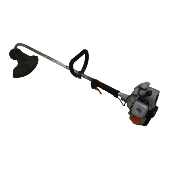
Grass Trimmer
Operator's Manual
MODELS
Read rules for safe operation and instructions carefully. ECHO provides an Operator's
Manual and a Safety Manual. Both must be read and understood for proper and safe
operation.
X7532270904
GT-2000 TYPE 1E
Serial Number 001001 & Up
GT-2400 TYPE 1E
Serial Number 001001 & Up Commercial Use
WARNING
Occasional Use
DANGER
89869544434
03/01
Advertisement
Table of Contents

Related Manuals for Echo GT-2000


Summary of Contents for Echo GT-2000
- Page 1 Grass Trimmer Operator's Manual MODELS Read rules for safe operation and instructions carefully. ECHO provides an Operator's Manual and a Safety Manual. Both must be read and understood for proper and safe operation. X7532270904 GT-2000 TYPE 1E Serial Number 001001 & Up GT-2400 TYPE 1E Serial Number 001001 &...
-
Page 2: Table Of Contents
NTRODUCTION Welcome to the ECHO family. This ECHO product was designed and manufactured to provide long life and on-the-job- dependability. Read and understand this manual and the SAFETY MANUAL you found in the same package. You will find both easy to use and full of helpful operations tips and SAFETY messages. -
Page 3: Manual Safety Symbols And Important Information
INCORPORATED, 400 Oakwood Road, Lake Zurich, IL 60047. •Keep shield and other components in place and in good condition. Do not use attachments or other parts not approved by ECHO. GT style (non-blade capable) units must not be converted to blade use except Maxi- Cuts or similar ECHO approved attachments. -
Page 4: International Symbols
See Assembly for proper adjustment. • Have repairs done only by an authorized ECHO Service Dealer. • Do not use any attachment, accessory or replacement part unless it is recommended in the Operator's Manual. -
Page 5: Fuel
PERSONAL CONDITION AND SAFETY EQUIPMENT Trimmer/Brush Cutter users risk injury to themselves and others if the trimmer/brush cutter is used improperly and or safety precautions are not followed. Proper clothing and safety gear must be worn when operating a trimmer. - Page 6 Trimmer/Brush Cutter handles. Gloves also reduce the transmission of machine vibration to your hands. Hearing Protection -- ECHO recommends wearing hearing protection whenever unit is used. Proper Clothing -- Wear snug fitting, durable clothing; • Pants should have long legs, shirts with long sleeves.
-
Page 7: Safe Operation
• Spectators and fellow workers must be warned, and children and animals prevented from coming nearer than 15 m (50 ft.) while the trimmer is in use. Operation Use Proper Clothing & Equipment • Before starting the unit, equip yourself and any other person working within the 15 m (50 ft.) Safety Zone with the required... -
Page 8: Extended Operation/Extreme Conditions
• Limit the hours of operation. Try to fill each day with jobs where operating the trimmer or other hand-held power equipment is not required. • If you experience discomfort, redness and swelling of the fingers followed by whitening and loss of feeling, consult your physician before further exposing yourself to cold and vibration. -
Page 9: Description
The ECHO product you purchased has been factory pre-assembled for your convenience. Due to packaging restrictions, shield installation and positioning of the front handle are necessary. After opening the carton, check for damage. Immediately notify your retailer or ECHO Dealer of damaged or missing parts. Use the contents list to check for missing parts. - Page 11 CUT-OFF KNIFE - Trims line to the correct length (5 in.). If trimmer is operated without a cut-off knife the line will become too long - more than (5 in.) - the operating speed will slow, the engine overheat and performance will suffer.
-
Page 12: Specifications
PECIFICATIONS . t i " l f f ) l i . l f i r t ) . t... -
Page 13: Assembly
SSEMBLY Tools Required: Locking Tool PLASTIC SHIELD 1. Snap the shield over the bearing housing. 2. Install bolt (A), washer (B) and wing nut (C). NYLON LINE HEAD 1. Align locating hole in locating plate with hole in bearing housing. 2. -
Page 14: Pre-Operation
EPA Phase I/California Emission Defect Warranty Explanation.) IMPORTANT Echo Premium 2-Stroke Oil may be mixed at 50:1 ratio for applica- tion in all Echo engines sold in the past regardless of ratio speci- fied in those manuals. Mixing Instructions 1. - Page 15 IMPORTANT Spilled fuel is a leading cause of hydrocarbon emissions. Some states may require the use of automatic fuel shut-off containers to reduce fuel spillage. Contact your ECHO dealer for ordering information. After refueling; • Wipe any spilled fuel from the unit.
-
Page 16: Equipment Check
See Assembly for proper adjustment. • Have repairs done only by an authorized ECHO Service Dealer. • Do not use any attachment, accessory or replacement part unless it is recommended in the Operator's Manual. -
Page 17: Operation
WARNING The cutting attachment should not rotate at idle. If attachment rotates, readjust carburetor according to "Carburetor Adjustment" instructions in this manual or see your ECHO Dealer, otherwise serious personal injury may result. Stop Switch - Start/Run. Move stop switch button (A) away from the STOP position. -
Page 18: Starting Warm Engine
The cutting attachment should not rotate at idle. If attachment rotates, readjust carburetor according to "Carburetor Adjustment" instructions in this manual or see your ECHO Dealer, otherwise serious personal injury may result. Stop Switch - Start/Run. Move stop switch button (A) away from the STOP position. -
Page 19: Maintenance
ECHO Service Dealer for maintenance. To help you decide whether you want to DO-IT-YOURSELF or have the ECHO Dealer do it, each maintenance task has been graded. If the task is not listed see your Echo dealer for repairs. -
Page 20: Air Filter
AIR FILTER Level 1. Tools required: Cleaning brush, 25 - 50 mm (1 or 2 in.) medium bristle paint brush. Parts required: Air Filter P/N 13031054130 1. Close choke (Cold Start Position). This prevents dirt from entering the carburetor throat when the air filter is removed. Brush accumu- lated dirt from the air cleaner area. -
Page 21: Spark Plug
Level 2. Tools Required: Spark Plug socket wrench and screw driver, Feeler gauge. Preferably a wire gauge. Parts Required: Spark Plug, GT-2000 NGK BPMR-7A GT-2400 CHAMPION RCJ-7Y Remove spark plug and check for fouling, worn and rounded center electrode. Clean the plug or replace with a new one. DO NOT sand blast to clean. -
Page 22: Exhaust System
NOTE The throttle linkage remains assembled to the cover and the spark plug lead and grommet remain installed. IMPORTANT DO NOT use a metal scraper to remove dirt from the cylinder fins. Use the wooden stick or brush to remove dirt from the cylinder fins. Remove grass and leaves from the grid between the starter and fuel tank. -
Page 23: Carburetor Adjustment Emission Models
CARBURETOR ADJUSTMENT Emission Models (with limiter caps) Level 2. Tools required: Screwdriver, Tachometer (ECHO P/N 99051130017). Parts required: None. NOTE Every unit is run at the factory and the carburetor is set in compli- ance with EPA Phase 1 and California Emission Regulations. In addition, the carburetor is equipped with HI and LO needle adjustment limiters that prevent settings outside acceptable limits. -
Page 24: Idle Speed Adjustment
CARBURETOR ADJUSTMENT Non Emission Models (without limiter caps) Level 2. Tools required: Screwdriver, Tachometer (ECHO P/N 99051130017). NOTE If carburetor has limiter caps follow "Carburetor Adjustment" procedures for Type 1E models on previous page. Idle Speed Adjustment Turn "idle" speed adjustment screw (C) CW (clockwise) until cutting attachment begins to turn, then turn screw out CCW (counter clock- wise) until attachment stops turning. -
Page 25: Lubrication
Tools Required: Head locking tool - 1/8 in. dia. Rod (if head is to be removed) Parts Required: ECHO 0.080 (2mm) Nylon Trimmer Line 4.6 m (15 ft.) Shut engine off. Lay unit on the ground with head assembly up. -
Page 26: Nylon Line Replacement (Gt-2400)
Tools Required: Head locking tool - 1/8 in. dia. Rod (if head is to be removed) Parts Required: ECHO 2 mm (0.080) Nylon Trimmer Line 6m (20 ft.) Press tab and twist cover CCW (counter clockwise) to align arrows and remove cover. Lift spool from housing. - Page 27 Align arrows, and push down on cover and twist cover clockwise until tab locks cover in place. Pull both lines out and trim to cut-off knife length. Before installing, test head. Push center button while pulling on both lines. Trimmer line should advance approximately 1 (one) inch. RASS RIMMER...
-
Page 28: Troubleshooting
ROUBLESHOOTING Fuel vapors are extremely flammable and may cause fire and/or explosion. Never test for ignition spark near an open spark plug opening, otherwise serious personal injury may result. l f f t l i f t l i f WARNING DANGER t l i f... -
Page 29: Storage
TORAGE Long Term Storage (over 30 days) WARNING During operation the muffler or catalytic muffler and surrounding cover become hot. Always keep exhaust area clear of flammable debris during transportation or when storing, otherwise serious property damage or personal injury may result. - Page 30 NOTES...
- Page 31 RASS RIMMER PERATOR ANUAL NOTES...
-
Page 32: Servicing Information
• Sending a check or money order for $2.00 per Parts Catalog or $1.50 per Operator's Manual made payable to ECHO, INCORPORATED. State on a sheet of paper the model number and serial number of the ECHO unit you have, part number of the manual (if known), your name and address and mail to address below.