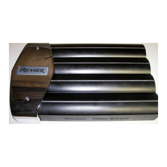
Pioneer PRS-X340 Service Manual
Bridgeable four-channel power amplifier
Hide thumbs
Also See for PRS-X340:
- Catalog (52 pages) ,
- Owner's manual (88 pages) ,
- Owner's manual (8 pages)
Table of Contents
Advertisement
Service
Manual
BRIDGEABLE FOUR-CHANNEL POWER AMPLIFIER
PRS-X340
CONTENTS
1. SAFETY INFORMATION............................................2
2. EXPLODED VIEWS AND PARTS LIST ......................2
3. SCHEMATIC DIAGRAM.............................................6
4. PCB CONNECTION DIAGRAM................................12
5. ELECTRICAL PARTS LIST........................................18
PIONEER CORPORATION
PIONEER ELECTRONICS SERVICE INC.
PIONEER EUROPE N.V.
Haven 1087 Keetberglaan 1, 9120 Melsele, Belgium
PIONEER ELECTRONICS ASIACENTRE PTE.LTD. 253 Alexandra Road, #04-01, Singapore 159936
C PIONEER CORPORATION 2000
PRS-X340/X1R/UC
4-1, Meguro 1-Chome, Meguro-ku, Tokyo 153-8654, Japan
P.O.Box 1760, Long Beach, CA 90801-1760 U.S.A.
6. ADJUSTMENT .........................................................24
7. GENERAL INFORMATION.......................................25
7.1 DISASSEMBLY ..................................................25
8. OPERATIONS AND SPECIFICATIONS ....................26
K-ZZA. MAR. 2000 Printed in Japan
ORDER NO.
CRT2482
X1R/UC,EW
Advertisement
Table of Contents

Related Manuals for Pioneer PRS-X340


Summary of Contents for Pioneer PRS-X340
-
Page 1: Table Of Contents
PIONEER ELECTRONICS SERVICE INC. P.O.Box 1760, Long Beach, CA 90801-1760 U.S.A. PIONEER EUROPE N.V. Haven 1087 Keetberglaan 1, 9120 Melsele, Belgium PIONEER ELECTRONICS ASIACENTRE PTE.LTD. 253 Alexandra Road, #04-01, Singapore 159936 C PIONEER CORPORATION 2000 K-ZZA. MAR. 2000 Printed in Japan... -
Page 2: Safety Information
PRS-X340 1. SAFETY INFORMATION - PRS-X340/X1R/UC CAUTION This service manual is intended for qualified service technicians; it is not meant for the casual do-it-yourselfer. Qualified technicians have the necessary test equipment and tools, and have been trained to properly and safely repair complex products such as those covered by this manual. - Page 3 PRS-X340 NOTE: - Parts marked by “*” are generally unavailable because they are not in our Master Spare Parts List. - Screws adjacent to mark on the product are used for disassembly. - PACKING SECTION PARTS LIST Part No. Mark No. Description...
- Page 4 PRS-X340 2.2 EXTERIOR...
- Page 5 23 Fuse Holder HKE0012 24 Terminal(CN901) HKE0020 46 Screw SMZ50H300FCR 25 Connector(CN301) HKE0030 (2) CONTRAST TABLE PRS-X340/X1R/UC and PRS-X340/X1R/EW are constructed the same except for the following: Part No. Mark No. Description PRS-X340/X1R/UC PRS-X340/X1R/EW 4 Badge HAM0013 HAM0014 14 Amp Unit...
-
Page 6: Schematic Diagram
PRS-X340 3. SCHEMATIC DIAGRAM 3.1 OVERALL CONNECTION DIAGRAM(GUIDE PAGE) Note: When ordering service parts, be sure to refer to “EXPLODED VIEWS AND PARTS LIST” or “ELECTRICAL PARTS LIST”. LOW XOVER NETWORK UNIT AMP UNIT HP/LP FILTER BP FILTER 40-120Hz ISOLATOR... - Page 7 PRS-X340 GAIN=8.5-33dB CB(A) CB(B) CN301 GAIN=8.5-33dB CN301 PRS-X340/X1R/EW CN904 CN903 CN902 CN901...
- Page 8 PRS-X340 CN103-2 CN104-2 CN101-2 CN102-2 CN102 CN104 CN101 CN103 A-a B C...
- Page 9 PRS-X340 A-a C...
- Page 10 PRS-X340...
- Page 11 PRS-X340...
-
Page 12: Pcb Connection Diagram
PRS-X340 4. PCB CONNECTION DIAGRAM 4.1 AMP UNIT NOTE FOR PCB DIAGRAMS 1. The parts mounted on this PCB CN104 include all necessary parts for several destination. For further information for respective destinations, be sure to check with the schematic diagram. - Page 13 PRS-X340 SIDE A...
- Page 14 PRS-X340 AMP UNIT...
- Page 15 PRS-X340 SIDE B...
- Page 16 PRS-X340 4.2 NETWORK PCB(A) SIDE A NETWORK PCB(A) CN101 OFF, LPF, HPF, BPF LOW, HIGH SIDE B NETWORK PCB(A)
- Page 17 PRS-X340 4.3 NETWORK PCB(B) SIDE A NETWORK PCB(B) CN103 LOW, HIGH OFF, LPF, HPF SIDE B NETWORK PCB(B)
-
Page 18: Electrical Parts List
PRS-X340 5. ELECTRICAL PARTS LIST NOTE: - Parts whose parts numbers are omitted are subject to being not supplied. - The part numbers shown below indicate chip components. Chip Resistor RS1/_S___J,RS1/__S___J Chip Capacitor (except for CQS..) CKS.., CCS.., CSZS..=====Circuit Symbol and No.===Part Name Part No. - Page 19 Part No. ------ ------------------------------------------ ------------------------- ------ ------------------------------------------ ------------------------- CFTLA124J50 Transistor 2SA970 CKSQYB182K50 Transistor 2SA970 CKSQYB182K50 94-4980 94-4980 Unit Number : HWH0132(PRS-X340/X1R/UC) 94-4980 : HWH0124(PRS-X340/X1R/EW) 94-4980 Unit Name : Amp Unit 94-4980 94-4980 MISCELLANEOUS 94-4980 94-4980 NJM2068D NJM2068D 94-4981 PA2027A 94-4981...
- Page 20 Semi-fixed 10k (B) CCP1206 RD1/4PU432J Semi-fixed 10k (B) CCP1206 RD1/4PU432J Fuse 30A HEK0030 RD1/4PU221J Fuse 30A HEK0030 RD1/4PU221J Fuse 30A HEK0030 RD1/4PU221J Network Unit(PRS-X340/X1R/UC) HWG0018 RD1/4PU221J Network Unit(PRS-X340/X1R/EW) HWG0017 RD1/4PU471J RD1/4PU471J RESISTORS RD1/4PU471J RD1/4PU471J RS1/10S222J RD1/4PU183J RS1/10S222J RD1/4PU183J RD1/4PU472J RD1/4PU183J...
- Page 21 PRS-X340 =====Circuit Symbol and No.===Part Name Part No. =====Circuit Symbol and No.===Part Name Part No. ------ ------------------------------------------ ------------------------- ------ ------------------------------------------ ------------------------- RD1/4PU622J RD1/4PU103J RD1/4PU622J RD1/4PU103J RD1/4PU622J RD1/4PU222J RD1/4PU622J RD1/4PU472J RD1/4PU104J RD1/4PU221J RD1/4PU104J RD1/4PU152J RD1/4PU104J RD1/4PU221J RD1/4PU104J RD1/4PU472J RD1/4PU101J RD1/4PU101J RD1/4PU101J...
- Page 22 PRS-X340 =====Circuit Symbol and No.===Part Name Part No. =====Circuit Symbol and No.===Part Name Part No. ------ ------------------------------------------ ------------------------- ------ ------------------------------------------ ------------------------- RS1/10S222J CMA030D2H RS1/10S472J CMA030D2H RS1/10S472J CMA030D2H RD1/4PU105J CMA030D2H RS1/2PMF220J CMA180J2H RS1/10S473J CMA180J2H RS1/2PMF220J CMA180J2H RS1/10S153J CMA180J2H RS1/10S102J 100µF/16V HCH0002 RD1/4PU272J 100µF/16V...
- Page 23 PRS-X340 =====Circuit Symbol and No.===Part Name Part No. =====Circuit Symbol and No.===Part Name Part No. ------ ------------------------------------------ ------------------------- ------ ------------------------------------------ ------------------------- CEAS100M16 CKSQYB102K50 CQMA472J50 CKSQYB102K50 CQMA472J50 CKSQYB473K50 CQMA472J50 CKSQYB473K50 CQMA472J50 CKSQYB223K50 CCSQCH470J50 CCSQCH470J50 CCSQCH470J50 CCSQCH470J50 CCSQCH470J50 CCSQCH470J50 CCSQCH470J50 CCSQCH470J50 CKSQYB471K50...
-
Page 24: Adjustment
PRS-X340 6. ADJUSTMENT - Setting Idle Current The following is the instructions for setting Idle current: Setting the idle current to the following ranges will require you to measure the voltage across the indicated resistors and adjusting the indicated variable resistors to set the required voltage range. -
Page 25: General Information
PRS-X340 7. GENERAL INFORMATION 7.1 DISASSEMBLY Case(Speaker) Removing the Case(Speaker) and the Case(RCA) (Fig.1) Remove the six screws. Remove the three screws. Remove the four screws and then remove the Case(Speaker). Remove the two screws Remove the four screws and then remove the Case(RCA). -
Page 26: Operations And Specifications
PRS-X340 8. OPERATIONS AND SPECIFICATIONS 8.1 OPERATIONS... - Page 27 PRS-X340...
-
Page 28: Connection Diagram
PRS-X340 Connection Diagram Fuse (30 A) 2 Special red battery wire [RD-223] (sold separately). Grommet After making all other connections at the amplifier, connect the battery wire terminal of the amplifier to the positive (+) terminal of the battery. Fuse (30 A) 2 Ground wire (black) [RD-223] (sold separately). -
Page 29: Specifications
PRS-X340 8.2 SPECIFICATIONS - PRS-X340/X1R/UC Power source ......................14.4 V DC (10.8 — 15.1 V allowable) Grounding system ............................Negative type Current consumption ......................43.7 A (at continuous power, 4 ) Average current drawn* ......................14.5 A (4 for four channels) 26.5 A (4... - Page 30 PRS-X340 - PRS-X340/X1R/EW Power source ......................14.4 V DC (10.8 — 15.1 V allowable) Grounding system ............................Negative type Current consumption ....................43.7 A (at continuous power, 4 ) Average current drawn* ...................... 14.5 A (4 for four channels) 26.5 A (4 for two channels) Fuse ..................................
- Page 31 PIONEER ELECTRONICS SERVICE INC. P.O.Box 1760, Long Beach, CA 90801-1760 U.S.A. PIONEER EUROPE NV Haven 1087 Keetberglaan 1, 9120 Melsele, Belgium PIONEER ELECTRONICS ASIACENTRE PTE.LTD. 253 Alexandra Road, #04-01, Singapore 159936 C PIONEER CORPORATION 2000 K-ZZS. DEC. 2000 Printed in Japan...