Eaton Powerware 9130 User Manual
700–3000 va ups
Hide thumbs
Also See for Powerware 9130:
- User manual ,
- Specifications (4 pages) ,
- Installation manual (274 pages)
Table of Contents
Advertisement
Advertisement
Table of Contents

Related Manuals for Eaton Powerware 9130


Summary of Contents for Eaton Powerware 9130
- Page 1 Eaton 9130 UPS ® 700–3000 VA User's Guide...
- Page 2 Class A EMC Statements (Low Voltage Models over 1500 VA) FCC Part 15 This equipment has been tested and found to comply with the limits for a Class A digital device, pursuant to NOTE part 15 of the FCC Rules. These limits are designed to provide reasonable protection against harmful interference when the equipment is operated in a commercial environment.
- Page 3 (Low Voltage Models up to 1500 VA and FCC Part 15 This equipment has been tested and found to comply with the limits for a Class B digital device, pursuant to NOTE part 15 of the FCC Rules. These limits are designed to provide reasonable protection against harmful interference in a residential installation.
-
Page 4: Special Symbols
Requesting a Declaration of Conformity Units that are labeled with a CE mark comply with the following harmonized standards and EU directives: Harmonized Standards: IEC 61000-3-12 EU Directives: 73/23/EEC, Council Directive on equipment designed for use within certain voltage limits 93/68/EEC, Amending Directive 73/23/EEC 89/336/EEC, Council Directive relating to electromagnetic compatibility 92/31/EEC, Amending Directive 89/336/EEC relating to EMC... -
Page 5: Table Of Contents
Table of Contents Introduction ............Safety Warnings . - Page 6 TABLE OF CONTENTS Retrieving the Event Log ..............Setting Power Strategy .
- Page 7 Warranty ............Two-Year Limited Warranty (US and Canada) Ten-Year Pro-Rated Limited Warranty (US and Canada) Load Protection Guarantee (US and Canada)
- Page 8 TABLE OF CONTENTS 164201718 Rev 2 www.powerware.com Eaton ® 9130 UPS (700–3000 VA) User's Guide...
-
Page 9: Introduction
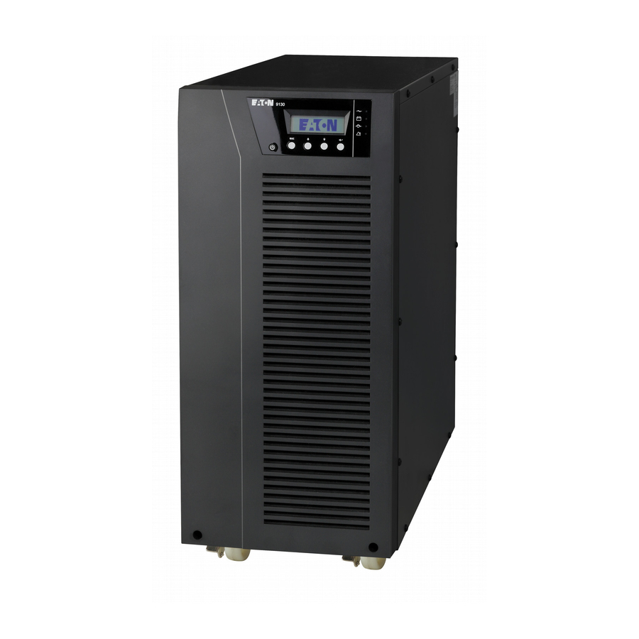
Chapter 1 Introduction The Eaton Powerware the most common power problems, including power failures, power sags, power surges, brownouts, line noise, high voltage spikes, frequency variations, switching transients, and harmonic distortion. Power outages can occur when you least expect it and power quality can be erratic. - Page 10 INTRODUCTION Figure 1 shows the Eaton 9130 rackmount UPS, and Figure 2 shows the optional rackmount EBM. Figure 3 shows the Eaton 9130 tower UPS and optional EBM. Figure 3. The Eaton 9130 Tower UPS and EBM (2000–3000 VA Models Shown) Eaton ®...
-
Page 11: Safety Warnings
Chapter 2 Safety Warnings This manual contains important instructions that you should follow during installation and maintenance of the UPS and batteries. Please read all instructions before operating the equipment and save this manual for future reference. This UPS contains LETHAL VOLTAGES. All repairs and service should be performed by AUTHORIZED SERVICE PERSONNEL ONLY. - Page 12 SAFETY WARNINGS Batteries can present a risk of electrical shock or burn from high short-circuit current. Observe proper precautions. Servicing should be performed by qualified service personnel knowledgeable of batteries and required precautions. Keep unauthorized personnel away from batteries. Proper disposal of batteries is required. Refer to your local codes for disposal requirements.
-
Page 13: Belangrijke Veiligheidsinstructies
Batterierne kan give risiko for elektrisk stød eller brandsår forårsaget af høj kortslutningsstrøm. Overhold gældende forsigtighedsregler. Servicering skal udføres af kvalificeret servicepersonale med kendskab til batterier og gældende forsigtighedsregler. Hold uautoriseret personale væk fra batterierne. Korrekt bortskaffelse af batterier er påkrævet. Overhold gældende lokale regler for bortskaffelsesprocedurer. -
Page 14: Tarkeita Turvaohjeita
SAFETY WARNINGS De uitgangsoverstroombeveiliging en de stroomonderbreker moeten door derden worden geleverd. Om aan de internationale normen en bedradingsvoorschriften te voldoen mag de gehele apparatuur die op de uitgang van deze UPS is aangesloten, geen aardlekstroom van meer dan 3,5 milliampère hebben. Batterijen leveren gevaar op voor elektrische schokken en kunnen brandwonden veroorzaken door een grote kortsluitstroom. - Page 15 Pienennä tulipalon vaaraa kytkemällä vain piiriin, jossa on 100 ampeerin maksimihaarapiirin ylivirtasuoja kansallisen sähkölainsäädännön (ANSI/NFPA 70) mukaan. Muiden on toimitettava lähdön ylivirtasuoja ja irtikytkentäkytkin. Kansainväliset normit ja johdotusmääräykset vaativat, että kaikkien tämän UPS-laitteen ulostulokytkentöjen yhteinen maavuotovirta ei ylitä 3,5 milliampeeria (mA). Akut voivat aiheuttaa sähköiskun tai palovammojen vaaran johtuen suuresta oikosulkuvirrasta.
-
Page 16: Wichtige Sicherheitsanweisungen
SAFETY WARNINGS Afin de réduire les risques d'incendie, ne raccordez qu'à un circuit muni d'une protection de surintensité du circuit de dérivation maximum de 100 ampères conformément au NEC (Code Électrique National) des États-Unis, ANSI/NFPA 70. La protection de surintensité de sortie ainsi que le sectionneur doivent être fournis par des tiers. -
Page 17: Avvisi Di Sicurezza
Dieses USV (Unterbrechungsfreies Stromversorgungssystem) enthält eine eigene Energiequelle (Batterien). Der USV-Ausgang kann Spannung führen, auch wenn das USV nicht an eine Wechselstromquelle angeschlossen ist. Um die Brand‐ oder Elektroschockgefahr zu verringern, diese USV nur in Gebäuden mit kontrollierter Temperatur und Luftfeuchtigkeit installieren, in denen keine leitenden Schmutzstoffen vorhanden sind. - Page 18 SAFETY WARNINGS La TENSIONE contenuta in questo gruppo statico di continuità è LETALE. Tutte le operazioni di riparazione e di manutenzione devono essere effettuate ESCLUSIVAMENTE DA PERSONALE TECNICO AUTORIZZATO. All'interno del gruppo statico di continuità NON vi sono PARTI RIPARABILI DALL'UTENTE. L'UPS contiene la propria fonte di energia (batterie).
-
Page 19: Viktig Sikkerhetsinformasion
Viktig Sikkerhetsinformasion Denne håndboken inneholder viktige instruksjoner som du bør overholde ved montering og vedlikehold av UPS-enheten og batteriene. Les alle instruksjoner før utstyret tas i bruk, og gjem håndboken til fremtidig referanse. Denne UPS'en inneholder LIVSFARLIGE SPENNINGER. All reparasjon og service må kun utføres av AUTORISERT SERVICEPERSONALE. - Page 20 SAFETY WARNINGS Regulamentos de Segurança Este manual contém instruções importantes que devem ser seguidas durante a instalação e manutenção do no-break e das baterias. Leia todas as instruções antes de operar o equipamento e guarde este manual para consultá-lo futuramente. A UPS contém VOLTAGEM MORTAL.
- Page 21 Ïðåäóïðåæäåíèÿ ïî ìåðàì áåçîïàñíîñòè ÂÀÆÍÛÅ ÓÊÀÇÀÍÈß ÏÎ ÌÅÐÀÌ ÁÅÇÎÏÀÑÍÎÑÒÈ Â äàííîì ðóêîâîäñòâå ñîäåðæàòñÿ âàæíûå èíñòðóêöèè ïî óñòàíîâêå è îáñëóæèâàíèþ èñòî÷íèêà áåñïåðåáîéíîãî ïèòàíèÿ (ÈÁÏ) è áàòàðåé. Ïåðåä ðàáîòîé ñ îáîðóäîâàíèåì ïðî÷òèòå âñå èíñòðóêöèè. Ñîõðàíèòå äàííîå ðóêîâîäñòâî äëÿ äàëüíåéøåãî èñïîëüçîâàíèÿ.  äàííîì ÈÁÏ èìåþòñÿ ÑÌÅÐÒÅËÜÍÎ ÎÏÀÑÍÛÅ ÍÀÏÐßÆÅÍÈß. Âñå ðàáîòû...
-
Page 22: Advertencias De Seguridad
SAFETY WARNINGS Âûñîêîå íàïðÿæåíèå, âûçâàííîå êîðîòêèì çàìûêàíèåì â áàòàðåå, ìîæåò ïðèâåñòè ê ïîðàæåíèþ ýëåêòðè÷åñêèì òîêîì èëè îæîãó. Ñîáëþäàéòå ìåðû ïðåäîñòîðîæíîñòè. Òåõíè÷åñêîå îáñëóæèâàíèå äîëæíî îñóùåñòâëÿòüñÿ êâàëèôèöèðîâàííûì ïåðñîíàëîì ïî ðàáîòå ñ èñòî÷íèêàìè ïèòàíèÿ, çíàêîìûì ñ ìåðàìè ïðåäîñòîðîæíîñòè. Íå äîïóñêàéòå ê ðàáîòå ñ áàòàðåÿìè ïîñòîðîííèõ. Íåîáõîäèìî... - Page 23 La protección contra sobrecorriente de salida y el conmutador de desconexión debe suministrarse por parte de terceros. Para cumplir con los estándares internacionales y las normas de instalación, la totalidad de los equipos conectados a la salida de este SIE no debe tener una intensidad de pérdida a tierra superior a los 3,5 miliamperios.
- Page 24 SAFETY WARNINGS För att reducera faran för brand får anslutning endast utföras till en krets som skyddas med överbelastningsskydd på maximalt 100 ampere i enlighet med NEC, ANSI/NFPA 70. Utgående överbelastningssydd och kretsbrytare måste levereras av annan leverantör. För att överensstämma med internationell standard och installationsföreskrifter får inte den totala utrustning som anslutits till uttagen på...
-
Page 25: Installation
Chapter 3 Installation This section explains: Equipment inspection Unpacking the cabinet Checking the accessory kit Cabinet installation (rackmount and tower) Wiring installation Initial startup Inspecting the Equipment If any equipment has been damaged during shipment, keep the shipping cartons and packing materials for the carrier or place of purchase and file a claim for shipping damage. -
Page 26: Unpacking The Cabinet
INSTALLATION Unpacking the Cabinet Unpacking the cabinet in a low-temperature environment may cause condensation to occur in and on the cabinet. Do not install the cabinet until the inside and outside of the cabinet are absolutely dry (hazard of electric shock). The cabinet is heavy (see page 78). -
Page 27: Rackmount Installation
Rackmount Installation The Eaton 9130 rackmount cabinet comes with all of the hardware required for installation in a standard EIA or JIS seismic rackmount configuration with square and round mounting holes. The rail assemblies adjust to mount in 48-cm (19-inch) racks with front to rear rail distances from 61 to 76 cm (24 to 30 inches) deep. -
Page 28: Rackmount Setup
INSTALLATION Rackmount Setup The cabinet is heavy (see page 78). Removing the cabinet from its carton requires a minimum of two people. If installing optional EBM(s), install the EBM(s) directly below the UPS so that all wiring between the cabinets is installed behind the front covers and is inaccessible to users. NOTE Mounting rails are required for each individual cabinet. - Page 29 2. Select the proper holes in the rack for positioning the UPS in the rack (see Figure 5). The rails occupy four positions on the front and rear of the rack. 3. Secure one rail assembly to the front of the rack with one M6 16 pan-head screw and one M6 cage nut.
- Page 30 INSTALLATION NOTE There are two sets of four mounting holes on each side of the UPS: a forward position and a middle position. Choose the position that meets your configuration needs. 10. If installing optional cabinets, repeat Steps 8 and 9 for each cabinet. 11.
-
Page 31: Rackmount Wiring Installation
13. Optional. Insert a rear stop bracket through the inside of each rail behind the UPS. Rotate each bracket and slide the bracket until it fits tightly against the UPS's rear panel. Secure each bracket to the UPS with one M3 8 pan-head screw. See Figure 8. Repeat for any optional cabinets. - Page 32 INSTALLATION NOTE A ribbon cable connects the LCD control panel to the UPS. Do not pull on the cable or disconnect it. A small amount of arcing may occur when connecting the internal batteries. This is normal and will not harm personnel. Connect the cables quickly and firmly. 2.
- Page 33 Up to 1500 VA Models Figure 10. Connecting the UPS Internal Batteries 3. If you are installing EBMs, see the following section, “Connecting the EBM(s),” before continuing with the UPS installation. 4. Replace the UPS right front cover. To replace the cover, verify that the ribbon cable is protected and (if EBMs are installed) the EBM cable is routed through the knockout on the bottom of the cover.
-
Page 34: Connecting The Ebm(S)
INSTALLATION Connecting the EBM(s) To install the optional EBM(s) for a UPS: 1. On the bottom of the UPS right front cover, remove the EBM cable knockout (see Figure 11). NOTE Use care to protect the LCD control panel and the connected ribbon cable from damage. - Page 35 EBM Cover Hook Bottom EBM Cable Knockout (underneath cover) Figure 12. Removing the EBM Front Cover 3. For the bottom (or only) EBM, remove the EBM cable knockout on the top of the EBM front cover. See Figure 12 for the location of the top EBM cable knockout.
- Page 36 INSTALLATION A small amount of arcing may occur when connecting an EBM to the UPS. This is normal and will not harm personnel. Insert the EBM cable into the UPS battery connector quickly and firmly. 5. Plug the EBM cable(s) into the battery connector(s) as shown in Figure 13.
-
Page 37: Tower Installation
7. Replace the EBM front cover. To replace the cover, verify that the EBM cables are routed through the EBM cover knockouts, then slide the cover from the left to the right until it connects with the cover hook near the left side of the EBM cabinet. -
Page 38: Tower Wiring Installation
INSTALLATION Tower Wiring Installation This section explains: Installing the UPS, including connecting the UPS internal batteries Connecting any optional EBMs Installing the UPS NOTE Do not make unauthorized changes to the UPS; otherwise, damage may occur to your equipment and void your warranty. NOTE Do not connect the UPS power cord to utility until after installation is completed. - Page 39 A small amount of arcing may occur when connecting the internal batteries. This is normal and will not harm personnel. Connect the cables quickly and firmly. 2. Connect the internal battery connector (see Figure 15). Connect the white connectors together, connecting red to red, and black to black.
-
Page 40: Connecting The Ebm(S)
INSTALLATION 6. If you are installing power management software, connect your computer to one of the communication ports or optional connectivity card (see page 53). For the communication ports, use an appropriate cable (not supplied). 7. If an emergency power-off (disconnect) switch is required by local codes, see “Remote Emergency Power-off”... - Page 41 INSTALLATION Remove cable retention clip. Plug in EBM cable. Rotate clip. Reinstall cable retention clip. 1000–1500 VA Models 2000–3000 VA Models Figure 16. Connecting the EBMs 164201718 Rev 2 www.powerware.com Eaton ® 9130 UPS (700–3000 VA) User's Guide...
-
Page 42: Ups Initial Startup
INSTALLATION UPS Initial Startup To start up the UPS: NOTE Verify that the total equipment ratings do not exceed the UPS capacity to prevent an overload alarm. 1. Verify that the internal batteries are connected. Rack models. See “Installing the UPS” on page 23. Tower models. - Page 43 10. Verify that the indicator illuminates solid, indicating that the UPS is operating normally and any loads are powered. The UPS should be in Normal mode. 11. Press the button until the start screen appears. 12. If optional EBMs are installed, see “Configuring the UPS for EBMs” on page 51 to set the number of installed EBMs.
- Page 44 INSTALLATION 164201718 Rev 2 www.powerware.com Eaton ® 9130 UPS (700–3000 VA) User's Guide...
-
Page 45: Operation
Chapter 4 Operation This chapter contains information on how to use the Eaton 9130, including front panel operation, operating modes, UPS startup and shutdown, transferring the UPS between modes, retrieving the Event Log, setting the power strategy, and configuring bypass settings, load segments, and battery settings. -
Page 46: Changing The Language
OPERATION Table 1 shows the indicator status and description. Table 1. Indicator Descriptions Indicator Status Green Flashing Flashing Yellow Yellow Changing the Language Press and hold the first button on the left for approximately three seconds to select the language menu. This action is possible from any LCD menu screen. - Page 47 Table 2 shows the basic menu structure. Table 2. Menu Map for Display Functions Main Menu Submenu UPS Status Event Log Measurements Control Go to Bypass Start Battery Test Reset Error State Load Segments Restore Factory Settings Identification Settings User Settings Service Settings Eaton ®...
-
Page 48: User Settings
OPERATION User Settings The following table displays the options that can be changed by the user. Table 3. User Settings Description Change Language User Password Audible Alarms Set Date and Time NOTE Time is a 24-hour clock. Signal Inputs Relay Configuration Serial Port Configuration Control Commands from Serial Port Output Voltage... - Page 49 Table 3. User Settings (continued) Description Frequency Converter Overload Alarm Level Transfer to Bypass When Overload* Power Strategy Automatic Start Delay Automatic on Battery Shutdown Start on Battery NOTE Utility must be present and output enabled at initial UPS startup. Energy Saving Mode Remote Shutdown Delay Delayed Shutdown Delay...
- Page 50 OPERATION Table 3. User Settings (continued) Description Site Wiring Fault Alarm Bypass Voltage Low Limit* Bypass Voltage High Limit* Qualify Bypass* Synchronization Window* Unsynchronized Transfers* Number of Battery Strings Battery Charge Mode Temperature Compensated Charging Battery Charge % to Restart Battery Low Alarm Automatic Battery Support Tests Ambient Temperature Warning...
-
Page 51: Operating Modes
Table 3. User Settings (continued) Description Predictive Maintenance Notices Remote Emergency Power-off (REPO) Input Polarity * See “Configuring Bypass Settings” on page 48. Operating Modes The Eaton 9130 front panel indicates the UPS status through the UPS indicators (see Figure 17 on page 37). Normal Mode During Normal mode, the powered from the utility. -
Page 52: Bypass Mode
OPERATION If battery capacity becomes low while in Battery mode, the flashes slowly and the audible alarm beeps once every second. If the “Battery Low” alarm is set, the warning is approximate, and the actual time to shutdown may vary significantly. -
Page 53: Standby Mode
1 hour 30 minutes or until battery voltage drops below 1.75 volts per cell (whichever occurs first). If utility fails while the UPS is in Standby mode, the logic power supply turns off in approximately 10 seconds. If the UPS is waiting on commands and utility fails, unit and logic power turn off in approximately 30 seconds. -
Page 54: Starting The Ups On Battery
OPERATION 5. Check the UPS front panel display for active alarms or notices. Resolve any active alarms before continuing. See “Troubleshooting” on page 101. If the Check the UPS status from the front panel to view the active alarms. Correct the alarms and restart if necessary. 6. -
Page 55: Ups Shutdown
UPS Shutdown To shut down the UPS: 1. Press the The UPS starts to beep and shows a status of “UPS off pending...”. The UPS then transfers to Standby mode, and the turns off. NOTE Releasing the operating mode. 2. Switch off utility power where the UPS is connected. Transferring the UPS Between Modes From Normal to Bypass Mode. -
Page 56: Setting Power Strategy
OPERATION Setting Power Strategy On the High Efficiency setting, the UPS operates normally on Bypass, transfers to inverter in less than 10 ms when utility fails, and transfers back to Bypass in 1 minute after utility returns. The illuminates when the UPS transfers to Bypass. NOTE High Efficiency operation is available after one minute of stable power. -
Page 57: Configuring Load Segments
You can prohibit Bypass (”Never”) or always allow Bypass with no specification checking (”Always”). For “Always on UPS Fault,” transfer to Bypass is always made on UPS fault; otherwise, operation proceeds as with the default setting. Synchronization Window. The UPS tries to synchronize with Bypass when the Bypass frequency is less than the value set for the “Synchronization Window”... - Page 58 OPERATION To set the restart and shutdown delay times for each load segment: 1. Press any button to activate the menu options, then select SETTINGS, USER SETTINGS and AUTOMATIC START DELAY. 2. Set the restart delay for one load segment, and ENTER to confirm. 3.
-
Page 59: Configuring Battery Settings
Configuring Battery Settings Set the UPS for the number of EBMs installed, whether to run automatic battery tests, and automatic restart configuration. Configuring the UPS for EBMs To ensure maximum battery runtime, configure the UPS for the correct number of EBMs: 1. -
Page 60: Running Automatic Battery Tests
OPERATION Running Automatic Battery Tests Automatic battery tests run approximately every 30 days, unless disabled. During the test, the UPS transfers to Battery mode and discharges the batteries for 25 seconds under the existing load. NOTE The “UPS on Battery” notice and the “Battery Low” alarm do not activate during a battery test. -
Page 61: Communication
Chapter 5 Communication This section describes the: Communication ports (RS-232 and USB) Connectivity cards Remote Emergency Power-off (REPO) Relay output contacts Programmable signal inputs Modem operation Powerware LanSafe Figure 18 shows the location of the communication options and control terminals on a typical UPS. See “Rear Panels”... -
Page 62: Installing Communication Options And Control Terminals
COMMUNICATION Installing Communication Options and Control Terminals To install the communication options and control terminals: 1. Install the appropriate connectivity card and/or necessary cable(s) and connect the cables to the appropriate location. See Figure 18 and the following section, “Communication Options,”... - Page 63 When the communication cable is installed, power management software can exchange data with the UPS. The software polls the UPS for detailed information on the status of the power environment. If a power emergency occurs, the software initiates the saving of all data and an orderly shutdown of the equipment.
-
Page 64: Connectivity Cards
COMMUNICATION Connectivity Cards Connectivity cards allow the UPS to communicate in a variety of networking environments and with different types of devices. The Eaton 9130 has one available communication bay for the following connectivity cards: ConnectUPS -BD Web/SNMP Card - has SNMP and HTTP capabilities as well as monitoring through a Web browser interface;... - Page 65 NOTE For Europe, the emergency switch requirements are detailed in Harmonized document HD-384-48 S1, “Electrical Installation of the Buildings, Part 4: Protection for Safety, Chapter 46: Isolation and Switching.” Wire Function Terminal Wire Size Rating REPO 4–0.32 mm NOTE Leave the REPO connector installed in the REPO port on the UPS even if the REPO function is not needed.
-
Page 66: Relay Output Contacts
COMMUNICATION Relay Output Contacts The UPS incorporates three programmable relay outputs with potential free contacts for remote alarm indications: a standard relay port and two outputs in the RS-232 communication port. See Figure 18 on page 53 for the locations of the ports. An additional four relay outputs can be obtained with the compatible Relay Interface Card. -
Page 67: Programmable Signal Inputs
Programmable Signal Inputs The UPS incorporates four programmable signal inputs: one RS-232 input, two connectivity card inputs, and one REPO terminal input. See Figure 18 on page 53 for the locations of the ports. Configure the inputs with the “Signal Inputs” setting in “User Settings” on page 40. Table 6 shows the programmable settings for the signal inputs. -
Page 68: Modem Operation
UPS shutdown occurs. Eaton ® 9130 UPS (700–3000 VA) User's Guide Powerware Generic XCP for the manufacturer and 164201718 Rev 2 www.powerware.com Powerware 9130 . If the for the model. -
Page 69: Ups Maintenance
Chapter 6 UPS Maintenance This section explains how to: Care for the UPS and batteries Replace the UPS internal batteries and Extended Battery Modules (EBMs) Test new batteries Recycle used batteries or UPS Update the UPS firmware UPS and Battery Care For the best preventive maintenance, keep the area around the UPS clean and dust‐free. -
Page 70: Storing The Ups And Batteries
UPS MAINTENANCE Storing the UPS and Batteries If you store the UPS for a long period, recharge the battery every 6 months by connecting the UPS to utility power. The internal batteries charge to 90% capacity in less than 3 hours. However, Eaton recommends that the batteries charge for 48 hours after long-term storage. -
Page 71: Replacing Rackmount Ups Internal Batteries
Do not open or mutilate the battery or batteries. Released electrolyte is harmful to the skin and eyes and may be extremely toxic. Determine if the battery is inadvertently grounded. If inadvertently grounded, remove source from ground. Contact with any part of a grounded battery can result in electrical shock. - Page 72 UPS MAINTENANCE 2. Disconnect the internal battery connector (see Figure 24). 3. Up to 1500 VA models only. If the EBM cable is not connected to an EBM, unclip the EBM cable and move it to the left out of the way. See Figure 24.
- Page 73 5. Carefully pull the handle on the battery tray and slide the battery package slowly out onto a flat, stable surface; use two hands to support the battery package. See “Recycling the Used Battery or UPS” on page 73 for proper disposal. NOTE Verify that the replacement batteries have the same rating as the batteries being replaced.
-
Page 74: Replacing Tower Ups Internal Batteries
UPS MAINTENANCE Replacing Tower UPS Internal Batteries The UPS internal batteries are heavy (see page 78). Use caution when handling the heavy batteries. The internal batteries are located behind the UPS front cover. The internal batteries are packaged together as one unit for easier handling. To replace the batteries in the UPS: 1. - Page 75 2. Remove and retain the two screws holding the internal battery connector. Disconnect the internal battery connector. See Figure 26. Internal Battery Connector Figure 26. Replacing the UPS Internal Batteries 3. Remove and retain the two screws holding the battery cover plate. Grasp an edge of the battery cover plate and pull it forward gently.
- Page 76 UPS MAINTENANCE 6. Replace the battery cover plate into the slots at left, threading the battery connector through the access slot. Reinstall the retained screws. A small amount of arcing may occur when connecting the internal batteries. This is normal and will not harm personnel.
-
Page 77: Replacing Rackmount Ebms
Replacing Rackmount EBMs The EBM is heavy (see page 78). Lifting the cabinet into the rack requires a minimum of two people. To replace the EBMs: 1. Remove the front cover of each EBM. See Figure 27. To remove the cover, remove and retain the two screws on the right side of the cover. - Page 78 UPS MAINTENANCE 2. Unplug the EBM cable from the UPS. If additional EBMs are installed, unplug the EBM cable from the battery connector on each EBM. 3. If not already installed, install the supplied mounting brackets on the new EBM(s). 4.
-
Page 79: Replacing Tower Ebms
10. Replace the EBM front cover. To replace the cover, verify that the EBM cables are routed through the EBM cover knockouts, then slide the cover from the left to the right until it connects with the cover hook near the left side of the EBM cabinet. -
Page 80: Testing New Batteries
UPS MAINTENANCE 5. For each cable retention clip removed, rotate the clip and install it under each EBM cable connection using the retained screws. 6. Verify that the EBM connections are tight and that adequate bend radius and strain relief exist for each cable. Testing New Batteries To test new batteries: 1. -
Page 81: Recycling The Used Battery Or Ups
Recycling the Used Battery or UPS Contact your local recycling or hazardous waste center for information on proper disposal of the used battery or UPS. Do not dispose of the battery or batteries in a fire. Batteries may explode. Proper disposal of batteries is required. - Page 82 UPS MAINTENANCE 164201718 Rev 2 www.powerware.com Eaton ® 9130 UPS (700–3000 VA) User's Guide...
-
Page 83: Specifications
Chapter 7 Specifications Model Specifications This section provides the following specifications: Communication options Model lists Weights and dimensions Electrical input and output Environmental and safety Battery Table 8. Communication Options (All Models) Communication Bay Compatible Connectivity Cards Communication Ports Signal Inputs (4) programmable signal inputs (signal and signal return) for indicating building alarms Relay Output Contacts Table 9. - Page 84 SPECIFICATIONS Table 10. UPS Model List (Rackmount Models) Model PW9130L700R-XL2U PW9130L1000R-XL2U PW9130L1500R-XL2U PW9130L2000R-XL2U PW9130L2500R-XL2U PW9130L3000R-XL2U PW9130G1000R-XL2U PW9130G2000R-XL2U PW9130G2500R-XL2U PW9130G3000R-XL2U PW9130i1000R-XL2U PW9130i1500R-XL2U PW9130i2000R-XL2U PW9130i3000R-XL2U PW9130G1000R-XL2UEU PW9130G2000R-XL2UEU PW9130G2500R-XL2UEU PW9130G3000R-XL2UEU PW9130G1000R-XL2UAU PW9130G1500R-XL2UAU PW9130G2000R-XL2UAU PW9130G3000R-XL2UAU Eaton ® 9130 UPS (700–3000 VA) User's Guide Power Level 700 VA / 630W 1000 VA / 900W 1500 VA / 1350W...
- Page 85 Table 11. UPS Model List (Tower Models) Model PW9130L700T-XL PW9130L1000T-XL PW9130L1500T-XL PW9130L2000T-XL PW9130L3000T-XL PW9130G1000T-XL PW9130G2000T-XL PW9130G3000T-XL PW9130i700T-XL PW9130i1000T-XL PW9130i1500T-XL PW9130i2000T-XL PW9130i3000T-XL PW9130G1000T-XLEU PW9130G2000T-XLEU PW9130G3000T-XLEU PW9130G700T-XLAU PW9130G1000T-XLAU PW9130G1500T-XLAU PW9130G2000T-XLAU PW9130G3000T-XLAU Eaton ® 9130 UPS (700–3000 VA) User's Guide Power Level 700 VA / 630W 1000 VA / 900W 1500 VA / 1350W 2000 VA / 1800W...
- Page 86 SPECIFICATIONS Table 12. Weights and Dimensions (Rackmount Models) Model (Rackmount UPS) PW9130L700R-XL2U PW9130L1000R-XL2U PW9130G1000R-XL2U PW9130i1000R-XL2U PW9130G1000R-XL2UEU PW9130G1000R-XL2UAU PW9130L1500R-XL2U PW9130i1500R-XL2U PW9130G1500R-XL2UAU PW9130L2000R-XL2U PW9130G2000R-XL2U PW9130i2000R-XL2U PW9130G2000R-XL2UEU PW9130G2000R-XL2UAU PW9130L2500R-XL2U PW9130G2500R-XL2U PW9130G2500R-XL2UEU PW9130L3000R-XL2U PW9130G3000R-XL2U PW9130i3000R-XL2U PW9130G3000R-XL2UEU PW9130G3000R-XL2UAU Model (Rackmount EBM) PW9130N1000R-EBM2U PW9130N1500R-EBM2U PW9130N3000R-EBM2U Eaton ®...
- Page 87 Table 13. Weights and Dimensions (Tower Models) Model (Tower UPS) PW9130L700T-XL PW9130i700T-XL PW9130G700T-XLAU PW9130L1000T-XL PW9130G1000T-XL PW9130i1000T-XL PW9130G1000T-XLEU PW9130G1000T-XLAU PW9130L1500T-XL PW9130i1500T-XL PW9130G1500T-XLAU PW9130L2000T-XL PW9130G2000T-XL PW9130i2000T-XL PW9130G2000T-XLEU PW9130G2000T-XLAU PW9130L3000T-XL PW9130G3000T-XL PW9130i3000T-XL PW9130G3000T-XLEU PW9130G3000T-XLAU Model (Tower EBM) PW9130N1000T-EBM PW9130N1500T-EBM PW9130N3000T-EBM * 252 mm (9.92”) with feet ** 346 mm (13.62”) with feet Table 14.
- Page 88 SPECIFICATIONS Table 15. Electrical Input (Rackmount Models) Model PW9130L700R-XL2U PW9130L1000R-XL2U PW9130L1500R-XL2U PW9130L2000R-XL2U PW9130L2500R-XL2U PW9130L3000R-XL2U PW9130G1000R-XL2U PW9130G2000R-XL2U PW9130G2500R-XL2U PW9130G3000R-XL2U PW9130i1000R-XL2U PW9130i1500R-XL2U PW9130i2000R-XL2U PW9130i3000R-XL2U PW9130G1000R-XL2UEU PW9130G2000R-XL2UEU PW9130G2500R-XL2UEU PW9130G3000R-XL2UEU PW9130G1000R-XL2UAU PW9130G1500R-XL2UAU PW9130G2000R-XL2UAU PW9130G3000R-XL2UAU * 100V and 200V are derated by 20%. ** 110V and 208V are derated by 10%. Eaton ®...
- Page 89 Table 16. Electrical Input (Tower Models) Model PW9130L700T-XL PW9130L1000T-XL PW9130L1500T-XL PW9130L2000T-XL PW9130L3000T-XL PW9130G1000T-XL PW9130G2000T-XL PW9130G3000T-XL PW9130i700T-XL PW9130i1000T-XL PW9130i1500T-XL PW9130i2000T-XL PW9130i3000T-XL PW9130G1000T-XLEU PW9130G2000T-XLEU PW9130G3000T-XLEU PW9130G700T-XLAU PW9130G1000T-XLAU PW9130G1500T-XLAU PW9130G2000T-XLAU PW9130G3000T-XLAU * 100V and 200V are derated by 20%. ** 110V and 208V are derated by 10%. Eaton ®...
- Page 90 SPECIFICATIONS Table 17. Electrical Input Connections (Rackmount Models) Model PW9130L700R-XL2U PW9130L1000R-XL2U PW9130L1500R-XL2U PW9130L2000R-XL2U PW9130L2500R-XL2U PW9130L3000R-XL2U PW9130G1000R-XL2U PW9130G2000R-XL2U PW9130G2500R-XL2U PW9130G3000R-XL2U PW9130i1000R-XL2U PW9130i1500R-XL2U PW9130i2000R-XL2U PW9130i3000R-XL2U PW9130G1000R-XL2UEU PW9130G2000R-XL2UEU PW9130G2500R-XL2UEU PW9130G3000R-XL2UEU PW9130G1000R-XL2UAU PW9130G1500R-XL2UAU PW9130G2000R-XL2UAU PW9130G3000R-XL2UAU Eaton ® 9130 UPS (700–3000 VA) User's Guide Input Connection 5-15P Attached line cord 5-15P...
- Page 91 Table 18. Electrical Input Connections (Tower Models) Model PW9130L700T-XL PW9130L1000T-XL PW9130L1500T-XL PW9130L2000T-XL PW9130L3000T-XL PW9130G1000T-XL PW9130G2000T-XL PW9130G3000T-XL PW9130i700T-XL PW9130i1000T-XL PW9130i1500T-XL PW9130i2000T-XL PW9130i3000T-XL PW9130G1000T-XLEU PW9130G2000T-XLEU PW9130G3000T-XLEU PW9130G700T-XLAU PW9130G1000T-XLAU PW9130G1500T-XLAU PW9130G2000T-XLAU PW9130G3000T-XLAU Eaton ® 9130 UPS (700–3000 VA) User's Guide Input Connection 5-15P Attached line cord 5-15P Attached line cord...
- Page 92 SPECIFICATIONS Table 19. Electrical Output (All Models) All Models Voltage Regulation Efficiency Frequency Regulation Nominal Outputs Frequency Output Overload (Normal Mode) Output Overload (Bypass Mode) Output Overload (Battery Mode) Voltage Waveform Harmonic Distortion Transfer Time Power Factor Load Crest Factor Eaton ®...
- Page 93 Table 20. Electrical Output Connections (Rackmount Models) Model Output Connections PW9130L700R-XL2U PW9130L1000R-XL2U PW9130L1500R-XL2U PW9130L2000R-XL2U (1) L5-20R, (6) 5-20T PW9130L2500R-XL2U (1) L5-30R, (6) 5-20T, (2) 20A AC breakers PW9130L3000R-XL2U (1) L5-30R, (6) 5-20T, (2) 20A AC breakers PW9130G1000R-XL2U (1) L6-20, (2) 6-20R PW9130G2000R-XL2U (1) L6-20, (3) 6-20R PW9130G2500R-XL2U...
- Page 94 SPECIFICATIONS Table 21. Electrical Output Connections (Tower Models) Model Output Connections PW9130L700T-XL PW9130L1000T-XL PW9130L1500T-XL PW9130L2000T-XL (1) L5-20R, (4) 5-20T PW9130L3000T-XL (1) L5-30R, (4) 5-20T, (2) 20A AC breakers PW9130G1000T-XL (1) L6-20, (2) 6-20R PW9130G2000T-XL (1) L6-20, (4) 6-20R PW9130G3000T-XL (1) L6-30R, (1) L6-20R, (2) 6-20R PW9130i700T-XL PW9130i1000T-XL PW9130i1500T-XL...
- Page 95 Table 22. Environmental and Safety (All Models) Surge Suppression EMC Certifications <1500 VA: FCC Class B, VCCI Class B, >2000 VA: FCC Class A, VCCI Class A, EMC (Emissions) Safety Conformance Agency Markings Operating Temperature Storage Temperature Transit Temperature Relative Humidity Operating Altitude Transit Altitude Audible Noise...
- Page 96 SPECIFICATIONS Table 23. Battery Runtimes (in Minutes) at 100% Load (Rack Models) Model Internal Batteries PW9130L700R-XL2U PW9130L1000R-XL2U PW9130G1000R-XL2U PW9130i1000R-XL2U PW9130G1000R-XL2UEU PW9130G1000R-XL2UAU PW9130L1500R-XL2U PW9130i1500R-XL2U PW9130G1500R-XL2UAU PW9130L2000R-XL2U PW9130G2000R-XL2U PW9130i2000R-XL2U PW9130G2000R-XL2UEU PW9130G2000R-XL2UAU PW9130L2500R-XL2U PW9130G2500R-XL2U PW9130G2500R-XL2UEU PW9130L3000R-XL2U PW9130G3000R-XL2U PW9130i3000R-XL2U PW9130G3000R-XL2UEU PW9130G3000R-XL2UAU NOTE Battery times are approximate and vary depending on the load configuration and battery charge. Eaton ®...
- Page 97 Table 24. Battery Runtimes (in Minutes) at 100% Load (Tower Models) Model Internal Batteries PW9130L700T-XL PW9130i700T-XL PW9130G700T-XLAU PW9130L1000T-XL PW9130G1000T-XL PW9130i1000T-XL PW9130G1000T-XLEU PW9130G1000T-XLAU PW9130L1500T-XL PW9130i1500T-XL PW9130G1500T-XLAU PW9130L2000T-XL PW9130G2000T-XL PW9130i2000T-XL PW9130G2000T-XLEU PW9130G2000T-XLAU PW9130L3000T-XL PW9130G3000T-XL PW9130i3000T-XL PW9130G3000T-XLEU PW9130G3000T-XLAU NOTE Battery times are approximate and vary depending on the load configuration and battery charge. Eaton ®...
- Page 98 SPECIFICATIONS Table 25. Battery Internal Batteries Rackmount 700–1000 VA models: 36 Vdc (3 12V, 9 Ah) Configuration 1500 VA models: 48 Vdc (4 12V, 9 Ah) 2000–3000 VA models: 72 Vdc (6 12V, 9 Ah) Tower 700 VA models: 24 Vdc (2 12V, 9 Ah) Configuration 1000 VA models: 36 Vdc (3 12V, 9 Ah) 1500 VA models: 48 Vdc (4 12V, 9 Ah)
-
Page 99: Rear Panels
SPECIFICATIONS Rear Panels This section shows each model's rear panel. Receptacles in Load Segment 1 are shaded. Table 10 on page 76 lists the rackmount models. Table 11 on page 77 lists the tower models. Input and output components for each model are listed in Table 15 through Table 21 (pages 80 through 86). - Page 100 SPECIFICATIONS Eaton ® 9130 UPS (700–3000 VA) User's Guide Figure 31. Model PW9130G1000R-XL2UAU Figure 32. Model PW9130G1500R-XL2UAU Figure 33. Model PW9130L1500R-XL2U Figure 34. Model PW9130i1500R-XL2U 164201718 Rev 2 www.powerware.com...
- Page 101 SPECIFICATIONS Figure 35. Model PW9130L2000R-XL2U Figure 36. Model PW9130G2000R-XL2U Figure 37. Models PW9130i2000R-XL2U, PW9130G2000R-XL2UEU Figure 38. Model PW9130G2000R-XL2UAU 164201718 Rev 2 www.powerware.com Eaton ® 9130 UPS (700–3000 VA) User's Guide...
- Page 102 SPECIFICATIONS Figure 39. Models PW9130L2500R-XL2U, PW9130L3000R-XL2U Figure 40. Models PW9130G2500R-XL2U, PW9130G3000R-XL2U Figure 41. Models PW9130G2500R-XL2UEU, PW9130i3000R-XL2U, PW9130G3000R-XL2UEU Figure 42. Model PW9130G3000R-XL2UAU 164201718 Rev 2 www.powerware.com Eaton ® 9130 UPS (700–3000 VA) User's Guide...
- Page 103 SPECIFICATIONS Figure 43. Model PW9130L700T-XL Figure 44. Model PW9130L1000T-XL Figure 45. Model PW9130L1500T-XL Figure 46. Model PW9130L2000T-XL 164201718 Rev 2 www.powerware.com Eaton ® 9130 UPS (700–3000 VA) User's Guide...
- Page 104 SPECIFICATIONS Figure 47. Model PW9130L3000T-XL Figure 49. Model PW9130G2000T-XL Eaton ® 9130 UPS (700–3000 VA) User's Guide Figure 48. Model PW9130G1000T-XL Figure 50. Model PW9130G3000T-XL 164201718 Rev 2 www.powerware.com...
- Page 105 SPECIFICATIONS Figure 51. Model PW9130i700T-XL Figure 52. Model PW9130G1000T-XLEU and PW9130i1000T-XL Figure 53. Model PW9130i1500T-XL Figure 54. Models PW9130G2000T-XLEU and PW9130i2000T-XL 164201718 Rev 2 www.powerware.com Eaton ® 9130 UPS (700–3000 VA) User's Guide...
- Page 106 SPECIFICATIONS Figure 55. Models PW9130G3000T-XLEU and PW9130i3000T-XL Figure 57. Model PW9130G1000T-XLAU Eaton ® 9130 UPS (700–3000 VA) User's Guide Figure 56. Model PW9130G700T-XLAU Figure 58. Model PW9130G1500T-XLAU 164201718 Rev 2 www.powerware.com...
- Page 107 SPECIFICATIONS Figure 59. Model PW9130G2000T-XLAU Figure 60. Model PW9130G3000T-XLAU 164201718 Rev 2 www.powerware.com Eaton ® 9130 UPS (700–3000 VA) User's Guide...
- Page 108 SPECIFICATIONS 164201718 Rev 2 www.powerware.com Eaton ® 9130 UPS (700–3000 VA) User's Guide...
-
Page 109: Troubleshooting
Chapter 8 Troubleshooting The Eaton 9130 is designed for durable, automatic operation and also alerts you whenever potential operating problems may occur. Usually the alarms shown by the control panel do not mean that the output power is affected. Instead, they are preventive alarms intended to alert the user. - Page 110 TROUBLESHOOTING To check the Event Log for a history of conditions: 1. Press any button on the front panel display to activate the menu options. 2. Press the button until EVENT LOG displays. 3. Press the Enter button to display the list of conditions. You can also retrieve the entire Event Log in ASCII format.
- Page 111 Alarm or Condition Possible Cause Overload Power requirements exceed the UPS capacity (greater than 100% of nominal; see page 84 for specific output overload LED is on. ranges). 1 beep every second. Overtemperature The UPS internal temperature is too high or a fan has failed. At the warning level, the UPS generates the alarm but remains LED is on.
- Page 112 TROUBLESHOOTING Alarm or Condition Possible Cause The UPS does not start. The power cord is not connected correctly. The Remote Emergency Power-off (REPO) switch is active or the REPO connector is missing. The UPS operates normally, The equipment is not connected but some or all of the correctly to the UPS.
-
Page 113: Silencing The Alarm
Silencing the Alarm Press any button on the front panel display to silence the alarm. Check the alarm condition and perform the applicable action to resolve the condition. If the alarm status changes, the alarm beeps again, overriding the previous alarm silencing. Service and Support If you have any questions or problems with the UPS, call your Local Distributor or the Help Desk at one of the following telephone numbers... - Page 114 TROUBLESHOOTING 164201718 Rev 2 www.powerware.com Eaton ® 9130 UPS (700–3000 VA) User's Guide...
-
Page 115: Warranty
Powerware UPS Models: 3105, 9120, 9125, 9130, 9140, and FERRUPS up to 3.1 kVA ® WARRANTOR: The warrantor for the limited warranties set forth herein is Eaton Electrical Inc., a Delaware Corporation company (“Company”). LIMITED WARRANTY: This limited warranty (this “Warranty”) applies only to the original End-User (the “End-User”) of any Powerware 3105, 9120, 9125, 9130, 9140, and FERRUPS up to 3.1 kVA Products (individually and... - Page 116 WARRANTY WHAT THIS LIMITED WARRANTY DOES NOT COVER: This Warranty does not cover any defects or damages caused by: (a) failure to properly store the Product before installation, including the charge of batteries no later than the date indicated on the packaging; (b) shipping and delivery of the Product if shipping is FOB Factory; (c) neglect, accident, abuse, misuse, misapplication, or incorrect installation;...
-
Page 117: Ten-Year Pro-Rated Limited Warranty (Us And Canada)
Ten-Year Pro-Rated Limited Warranty (US and Canada) Powerware UPS Models: 5115, 5125, 5140, 9120, 9125, 9130, 9140, 9155, 9170+, and FERRUPS WARRANTOR: The warrantor for the limited warranties set forth herein is Eaton Electrical Inc., a Delaware Corporation company (“Company”). LIMITED WARRANTY: This pro-rated limited warranty (this “Warranty”) applies only to the original End-User (the... - Page 118 WARRANTY WHAT THIS LIMITED WARRANTY DOES NOT COVER: This Warranty does not cover any defects or damages caused by: (a) failure to properly store the Product before installation, including the charge of batteries no later than the date indicated on the packaging; (b) shipping and delivery of the Product if shipping is FOB Factory; (c) neglect, accident, abuse, misuse, misapplication, or incorrect installation;...
-
Page 119: Load Protection Guarantee (Us And Canada)
Load Protection Guarantee (US and Canada) Powerware UPS Models 3105, 5110, 5115, 5125, 9120, 9125, 9130, 9140, 9150, 9155, 9170+, and FERRUPS GUARANTOR: The Guarantor for the load protection guaranty set forth herein is Eaton Electrical Inc., a Delaware Corporation company (“Company”). LIMITED GUARANTY: This load protection guaranty (this “Guaranty”) applies only to the original End-User (the... - Page 120 WARRANTY WHAT THIS GUARANTY DOES NOT COVER: Any reimbursement or repair to End-User's equipment does not include reimbursement for or restoration of any data loss. This Guaranty does not cover any defects or damages caused by: (a) failure to properly store the Product before installation, including the charge of batteries no later than the date indicated on the packaging;...