Table of Contents
Advertisement
Quick Links
Advertisement
Table of Contents

Related Manuals for Acer RL70


Summary of Contents for Acer RL70
- Page 1 Acer Revo 70 Service Guide PRINTED IN TAIWAN...
-
Page 2: Revision History
Revision History Please refer to the table below for the updates made on this service guide. Date Chapter Updates... - Page 3 Copyright Copyright © 2011 by Acer Incorporated. All rights reserved. No part of this publication may be reproduced, transmitted, transcribed, stored in a retrieval system, or translated into any language or computer language, in any form or by any means, electronic, mechanical, magnetic, optical, chemical, manual or otherwise, without the prior written permission of Acer Incorporated.
- Page 4 Disclaimer The information in this guide is subject to change without notice. Acer Incorporated makes no representations or warranties, either expressed or implied, with respect to the contents hereof and specifically disclaims any warranties of merchantability or fitness for any particular purpose.
- Page 5 Conventions The following conventions are used in this manual: SCREEN Denotes actual messages that appear on screen. MESSAGES NOTE Gives additional information related to the current topic. WARNING Alerts you to any physical risk or system damage that might result from doing or not doing specific actions.
-
Page 6: Fru Information
Service Guide Coverage This Service Guide provides you with all technical information relating to the BASIC CONFIGURATION decided for Acer's "global" product offering. To better fit local market requirements and enhance product competitiveness, your regional office MAY have decided to extend the functionality of a machine (e.g. add-on card, modem, or extra memory capability). -
Page 7: Table Of Contents
Table of Contents System Tour Features Block Diagram System Components Front Panel Rear Panel Hardware Specifications and Configurations Power Management Function(ACPI support function) System Utilities CMOS Setup Utility Entering CMOS setup Navigating Through the Setup Utility Setup Utility Menus System Disassembly and Assembly Disassembly Requirements Pre-disassembly Procedure Removing... - Page 8 System Troubleshooting Hardware Diagnostic Procedure System Check Procedures Power System Check System External Inspection System Internal Inspection Beep Codes Checkpoints BIOS Recovery Jumper and Connector Information M/B Placement Jumper Setting Internal Header Pin Definition Connector Pin Definition FRU (Field Replaceable Unit) List Revo 70 Exploded Diagram Revo 70 FRU List viii...
-
Page 9: System Tour
Chapter 1 System Tour Features Below is a brief summary of the computer’s many feature: NOTE: The features listed in this section is for your reference only. The exact configuration of the system depends on the model purchased. Operating System Microsoft Windows 7 Home Premium X86 •... -
Page 10: Hard Disk
Mini-PCIe Mini-card(mini PCI Express)Slot Type: x1 • Mini-card Slot Quantity: 2 • Should meet mini-PCIe specification v1.2. • One slot is for Wireless Lan card, should keep the flexibility for both Mini-PCI-E and USB interface. • The other one is for TV Tuner (full size, colay with USB interface, and support half size also). •... -
Page 11: System Bios
Connector Pin: standard Intel FPIO pin definition. • USB 2.0/1.1Data transfer rate support. • Buzzer 1 on board buzzer. • All On-Board Connectors Rear I/O connectors • One HDMI output • One D-sub output • Two USB stack *2 • One RJ45 •... -
Page 12: Block Diagram
Block Diagram Chapter 1... -
Page 13: System Components
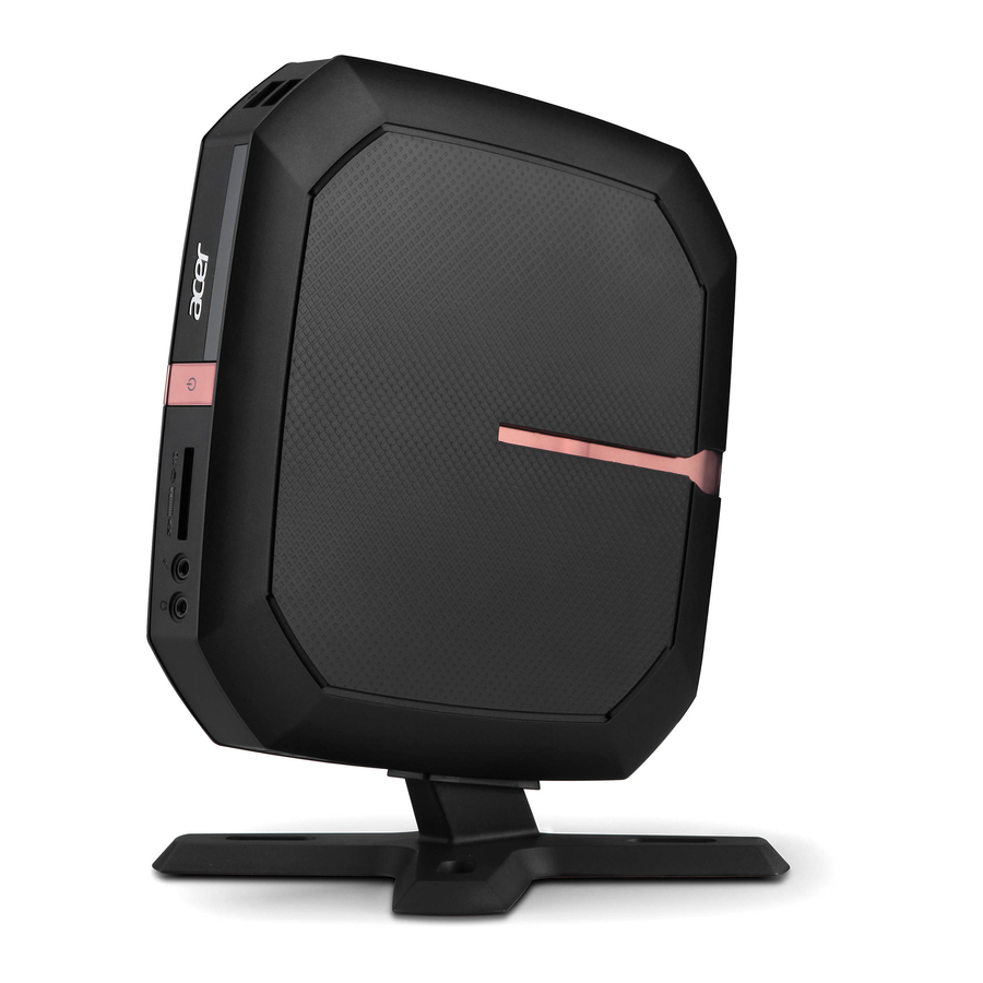
System Components This section is a virtual tour of the system’s interior and exterior components. Front Panel Component USB 2.0 port Optical drive eject button Power button/power indicator Media Card Reader(4 in 1: XD/SD/MMC/MS) Microphone-in jack Headphone/Speaker-out/line-out jack Computer stand Chapter 1... -
Page 14: Rear Panel
Rear Panel Component USB 2.0 port HDMI port S/PDIF port D-sub port RJ45 LAN Connector DC-in Jack Chapter 1... -
Page 15: Hardware Specifications And Configurations
Hardware Specifications and Configurations Processor Item Specification Type AMD E300/ E450 Socket Thermal design power Minimum operating speed 0 MHz (If Stop CPU Clock in Sleep State in BIOS Setup is set to Enabled.) BIOS Item Specification BIOS code programmer AMI Kernel with eMachines BIOS version P01-A0... -
Page 16: Memory Combinations
Memory Combinations Slot Memory Total Memory Slot 1 1GB,2GB 1GB ~2GB Slot 2 1GB,2GB 1GB ~2GB Maximum System Memory Supported 1GB ~4GB System Memory Item Specification Memory slot number 2 slot Support Memory size per socket 1GB,2GB Support memory type DDR3 SO-DIMM Support memory interface DDR3 1066/1333MHz... -
Page 17: Sata Interface
SATA Interface Item Specification SATA controller AMD Hudson D1 SATA controller resident bus PCI bus Number of SATA channel SATA X 2 Support bootable CD-ROM USB Port Item Specification Universal HCI USB 2.0/1.1 USB Class Support legacy keyboard for legacy mode USB Connectors Quantity Ports Quantity: 6 •... -
Page 18: Power Management Function(Acpi Support Function)
Power Management Function(ACPI support function) Device Standby Mode Independent power management timer for hard disk drive devices(0-15 minutes,time step=1minute). • Hard Disk drive goes into Standby mode(for ATA standard interface). • Disable V-sync to control the VESA DPMS monitor. • Resume method:device activated (keyboard for DOS, keyboard &mouse for Windows. -
Page 19: System Utilities
Chapter 2 System Utilities CMOS Setup Utility CMOS setup is a hardware configuration program built into the system ROM, called the complementary metal- oxide semiconductor (CMOS) Setup Utility. Since most systems are already properly configured and optimized, there is no need to run this utility. You will need to run this utility under the following conditions. When changing the system configuration settings •... -
Page 20: Entering Cmos Setup
Entering CMOS setup Turn on the server and the monitor. If the server is already turned on, close all open applications, then restart the server. During POST, press Delete. If you fail to press Delete before POST is completed, you will need to restart the server. The Setup Main menu will be displayed showing the Setup’s menu bar. -
Page 21: Setup Utility Menus
Setup Utility Menus Main The Setup Main menu includes the following main setup categories. Parameter Description System BIOS Version Version number of the BIOS setup utility. Build Date Date when the BIOS setup utility was built Processor Type of CPU installed on the system. Core Frequency Core speed of the CPU installed on the system. - Page 22 Advanced Parameter Description Miscellaneous Press Enter to access the Miscellaneous submenu Advanced Chipset Configuration Press Enter to access the Advanced Chipset Configuration submenu Integrated Peripherals Press Enter to access the Integrated Peripherals submenu PC Health Status Press Enter to access the PC Health Status submenu Chapter 2...
- Page 23 Miscellaneous Parameter Description Option AHCI Port 0/1/3 Displays the status of auto detection of the AHCI device. Spread Spectrum If you enable spread spertrum, it can significantly reduce the EMI (Electro- Enabled Magneticinterface) generated by the system and voltage according to its Disabled temperature.
-
Page 24: Advanced Chipset Configuration
Advanced Chipset Configuration AMD Cooler’n’Quiet When enabled, this feature allows the OS to reduce power consumption. Enabled When disabled, the system operates at maximum CPU speed. Disabled AMD EVP increase the virus Enabled When enabled, protecting. Disabled AMD-V Enables or disables the Virtualization Technology (VT) availability. If Enabled enabled, a virtual machine manager (VMM) can utilize the additional Disabled... -
Page 25: Integrated Peripherals
Integrated Peripherals Parameter Description Option Onboard SATA Controller Enables or disables the onboard SATA controller. Enabled Disabled Onboard SATA Mode Select an operating mode for the onboard SATA. Native IDE AHCI Onboard USB Controller Enables or disables the onboard USB controller. Enabled Disabled Legacy USB Support... -
Page 26: Pc Health Status
PC Health Status Parameter Description Option Smart Fan Enables or disables the smart system fan control function. Enabled Disabled Chapter 2... - Page 27 Power Parameter Description Option ACPI Suspend Mode Select an ACPI state. S3 (STR) S1 (POS) Deep Power Off Mode Enables or disables the deep power off mode. Enabled Disabled Power On by RTC Alarm Enables or Disables to wake up the system by RTC Alarm Function Enabled Disabled Power On by PCIE Devices...
- Page 28 Security Parameter Description Option Supervisor Password This item indicates whether a supervisor password has been set. If the password has been installed, Installed displays. If not, Not Installed displays. User Password This item allows you to change user password. Change Supervisor You can select this option and press <Enter>...
-
Page 29: Boot Options
Boot Options 1st/2nd/3rd/4th/5th Boot Specifies the boot order from the available devices. Device Hard Disk CD^DVD Removable Device EFI Device Priority Press Enter to access the EFI Device Priority submenu and specify the boot device priority sequence from available EFI devices. Hard Disk Drive Priority Press Enter to access the Hard Disk Drive Priority submenu and specify the boot device priority sequence from available hard drives. - Page 30 Exit Parameter Description Save & Exit Setup When you have completed the system configuration changes, select this option to leave the BIOS Setup Utility and reboot the computer, so the new system configuration parameters can Save & Exit Setup Enter take effect.
-
Page 31: System Disassembly And Assembly
Chapter 3 System Disassembly and Assemble This chapter contains step-by-step procedures on how to disassemble and assemble the desktop computer for maintenance and troubleshooting. Disassembly Requirements To disassemble the computer, you need the following tools: Wrist grounding strap and conductive mat for preventing electrostatic discharge •... -
Page 32: Pre-Disassembly Procedure
Pre-disassembly Procedure Before proceeding with the disassembly procedure, perform the steps listed below: Turn off the system and all the peripherals connected to it. Unplug the power cord from the power outlets. Unplug the power cord from the system. Unplug all peripheral cables from the system. Place the system unit on a flat, stable surface. -
Page 33: Removing The Computer Stand
Removing the Computer Stand If the computer stand install on the side of the unit, pls follow below picture to disassemble the computer stand. Slide the computer stand(1) and pull the computer stand(2) as the direction indicated. If the computer stand install on the bottom of the unit, pls follow below picture to disassemble the computer stand. -
Page 34: Removing The Top Cover
Removing the Top Cover Remove the screws securing the top cover. Find the two disassembly holes(1,2) and use a flat screwdriver to gently pry off the plastic shell cover. Remove top cover. WARNING:Please be careful when open the top cover, in order not to damage the EMI shielding. Chapter 3... -
Page 35: Removing The Optical Disc Drive
Removing the Optical Disc Drive NOTE: If your unit without optical disc drive, please ignore below step and refer to “Removing the sheet matal” on page 32. Remove the screw securing the ODD_cover. Remove the ODD_cover. Chapter 3... - Page 36 Disconnect the ODD SATA cable and power cable from the rear of the optical drive. Also disconnct the other end of the SATA cable and power cable from the mainboard. Remove the screws securing the ODD bracket. Chapter 3...
- Page 37 Pull the ODD bracket from the chassis. Remove the four screws that secure the optical drive to the ODD bracket. Pull the optical drive out of the drive bay. Chapter 3...
-
Page 38: Removing The Odd Base Cover
Removing the ODD Base Cover Remove the screws securing the ODD base cover. Use a flat screwdriver to gently pry off the ODD base cover. Chapter 3... - Page 39 Remove the ODD base cover. Chapter 3...
-
Page 40: Removing The Sheet Metal
Removing the Sheet Metal Remove the screws secureing the sheet matal. Remove the sheet matal. Chapter 3... -
Page 41: Removing The Heat Sink Fan Assembly
Removing the Heat Sink Fan Assembly Use a screwdriver to loosen the four screws on the heat sink as shown below. Note :CPU Fan has been highlighted with the yellow rectangle as above image shows.Please detach the CPU Fan and follow local regulations for disposal. Lift the heat sink fan assembly away from the main board. - Page 42 Disconnect fan cable from the motherboard connector. Chapter 3...
-
Page 43: Removing The Memory Modules
Removing the Memory Modules Open the holding clips securing the memory module. Gently pull the memory module to remove it from the SODIMM1 slot. Note: Circuit boards >10 cm² has been highlighted with the yellow rectangle as above image shows. Please detach the Circuit boards and follow local regulations for disposal. -
Page 44: Removing The Daughter Board
Removing the Daughter Board Remove the screw securing the daughter board. Lift the daughter board away from the main board. Chapter 3... -
Page 45: Removing The Wireless Lan Card
Removing the Wireless LAN Card Remove the wireless LAN antenna cable from connector of wireless LAN card(1) and detach the adhesion tape(2). Remove the screw securing the wireless LAN card. Note: Circuit boards >10 cm² has been highlighted with the yellow rectangle as above image shows. Please detach the Circuit boards and follow local regulations for disposal. - Page 46 Remove the WLAN module. Chapter 3...
-
Page 47: Removing The Main Board
Removing the Main Board Disconnect the IR Sensor cable from main board connector. Release the two locking tabs (1) and gently pull the cover out (2). Chapter 3... - Page 48 Remove the four screws that secure the main board to the chassis. Lift the board from the chassis. WARNING:Please be careful when lift the motherboard,in order not to damage the EMI shielding. Chapter 3...
-
Page 49: Removing The Hard Disk Drive
Removing the Hard Disk Drive Use screwdriver to loosen the four screws. Remove HDD from Main board connector. Chapter 3... -
Page 50: Removing The Led Lens
Remove the LED Lens Release the two locking tabs (1) and gently pull the LED lens out (2). Chapter 3... -
Page 51: Removing The Battery
Removing the Battery Place the motherboard on a clean, static-free work surface. Note: Circuit boards >10 cm² has been highlighted with the yellow rectangle as above image shows. Please detach the Circuit boards and follow local regulations for disposal. Disconnector the cable from the motherboard. Then remove the battery. Note: RTC battery has been highlighted with the yellow circle as above image shows.Please detach the RTC battery and follow local regulations for disposal. -
Page 52: Removing The Ir Sensor Cable
Removing the IR Sensor Cable Release the two locking tabs (1) and gently pull the IR Sensor cable out (2). Chapter 3... -
Page 53: Removing The Wlan Antennas Cable
Removing the WLAN Antennas Cable Release the WLAN antennas cable from the plastic clip(1), then detach the WLAN antennas cable(2). Chapter 3... -
Page 54: Removing The South Bridge Heat Sink
Removing the South Bridge Heat Sink Detach the south bridge heat sink. Chapter 3... -
Page 55: Assembly Requirements
Assemble Requirements To assemble the computer, you need the following tools: Wrist grounding strap and conductive mat for preventing electrostatic discharge • Flat-blade screwdriver • Philips screwdriver • Hex screwdriver • Plastic flat-blade screwdriver • Plastic tweezers • NOTE: The screws for the different components vary in size. During the assembly process, group the screws with the corresponding components to avoid mismatch when putting back the components. -
Page 56: Installing The Hard Disk Drive
Installing the Hard Disk Drive Take thewasher and the mainboard. Tear off protective paper of washer, Install the washer to the mainboard as below picture shown. Chapter 3... - Page 57 Install the HDD to the SATA slot of main board. Upset main board, confirm that the MB hole is aligned with the hole of HDD, use the four screwto secure the HDD. Chapter 3...
-
Page 58: Installing The Wireless Lan Card
Installing the Wireless Lan Card Install the wireless lan card to the main board ”MINI-PCIE1” slot. Press the wireless lan card down and use one screw to secure the wireless Lan card. Chapter 3... -
Page 59: Installing The Memory Modules
Installing the Memory Modules Insert the memory module into the SODIMM1 slot (1) and then press it down until it clicks into place (2). If a second memory module is available, install it in the DIMM2 slot by repeating step 1. Chapter 3... -
Page 60: Installing The Led Lens
Installing the LED Lens Install LED lens on nainboard. Chapter 3... -
Page 61: Installing The South Bridge Heat Sink
Installing the South Bridgbe Heat Sink Tear off the paper of South bridge heat sink. Paste heat sink on chassis. Chapter 3... -
Page 62: Installing The Antennas Of Wlan Card
Installing the Antennas Cable of WLAN Card Paste the WLAN antennas cable to the chassis(1), and install the WLAN antennas cable into the plastic clip(2). Chapter 3... -
Page 63: Installing The Ir Sensor Cable
Installing the IR Sensor cable Install the IR Sensor cable as below picture shown. Chapter 3... -
Page 64: Installing The Main Board
Installing the Main Board Slide the mainboard into the chassis, with the I/O ports of the mainboard extruding from their port holes, then lower the mainboard in place. Make sure the screw holes on the main board are aligned with those on the chassis. Secure the mainboard with four screws. - Page 65 Connect the the wireless LAN antenna cable to connector of wireless LAN card and use the adhesion tape to stick the wireless LAN antenna cable to mainboard(1), then connect the IR Sensor cable to mainboard connector(2). Chapter 3...
-
Page 66: Installing The Heat Sink Fan Assembly
Installing the Heat Sink Fan Assembly Position the heat sink assembly on top of the CPU, making sure the screws are aligned with the gaps on the main board. Secure the heat sink assembly using four screws. Chapter 3... - Page 67 Disconnect fan cable from the motherboard. Chapter 3...
-
Page 68: Installing The Daughter Board
Installing the Daughter Board Install the daughter board to the main board. Secure the daughter board using the screw. Chapter 3... -
Page 69: Installing The Sheet Metal
Installing the Sheet Metal Paste 1pc gasket on sheet metal as below picture shown. Position the sheet metal on top of the mianboard, making sure the screw holes on the sheet metal are aligned with the those on the mainboard, then secure the sheet metal using the four screws. Chapter 3... -
Page 70: Installing The Optical Disc Drive
Installing the Optical Disc Drive NOTE: If your unit without optical disc drive, please ignore below step and refer to “Installing the Top Cover “ on page 66. Slide the optical drive into the drive bay. Secure the optical drive to the ODD bracket using the four screws. Slide the ODD bracket to the ODD base cover. - Page 71 Secure the ODD bracket to the ODD base cover using two screws. Install the ODD base cover. Chapter 3...
- Page 72 Make sure the retention tabs of ODD base cover are securedly fastened to the chassis interior. Connect the ODD SATA cable and power cable to the rear of the optical drive. Also connct the other end of the SATA cable and power cable to the mainboard. Chapter 3...
- Page 73 Install the ODD_cover. Secure the ODD_cover using the screw. Chapter 3...
-
Page 74: Installing The Top Cover
Installing the Top Cover Install TV cap to cover TV card hole of chassisas as below picture shown. Install the top cover. Make sure the front bezel retention tabs are securedly fastened to the chassis interior. Secure the top cover using the two screws. Chapter 3... -
Page 75: Installing The Computer Stand
Installing the Computer Stand If you need to install the computer stand on the side of the unit, pls follow below picture to assemble the computer stand. Slide the computer stand(1) as the direction indicated. If you need to install the computer stand on the bottom of the unit, pls follow below picture to assemble the computer stand. -
Page 76: System Troubleshooting
Chapter 4 System Troubleshooting This chapter provides instructions on how to troubleshoot system hardware problems. Hardware Diagnostic Procedure IMPORTANT:The diagnostic tests described in this chapter are only intended to test Acer products. Non-Acer products, prototype cards, or modified options can give false errors and invalid system responses. -
Page 77: System Check Procedures
System Check Procedures Power System Check If the system will power on, skip this section. Refer to System External Inspection. If the system will not power on, do the following: Check if the power cable is properly connected to the system and AC source. •... -
Page 78: Beep Codes
Beep Codes Beep codes are used by the BIOS to indicate a serious or fatal error to the end user. Beep codes are used when an error occurs before the system video has been initialized. Beep codes will be generated by the system board speaker, commonly referred to as the PC speaker. -
Page 79: Checkpoints
Checkpoints A checkpoint is either a byte or word value output to I/O port 80h.The BIOS outputs checkpoints throughout bootblock and Power-On Self Test (POST) to indicate the task the system is currently executing. Checkpoint sare very useful in aiding software developers or technicians in debugging problems that occur during the pre- boot process. -
Page 80: Bootblock Recovery Code Checkpoints
Bootblock Recovery Code Checkpoints The Bootblock recovery code gets control when the BIOS determines that a BIOS recovery needs to occur because the user has forced the update or the BIOS checksum is corrupt. The following table describes the type of checkpoints that may occur during the Bootblock recovery portion of the BIOS. NOTE: Checkpoints may differ between different platforms based on system configuration. -
Page 81: Bios Recovery
BIOS Recovery Copy the target BIOS rom file to a USB disk. Rename the target BIOS to “amiboot.rom”.Plug the USB disk to computer that you want to recovery the system BIOS. Power on the system, BIOS recovery will be done. Wait for about 3 minutes the system will reboot automatically after flash update completed successfully. -
Page 82: Jumper And Connector Information
Chapter 5 Jumper and Connector Information M/B Placement Label Description Label Description REAR_USB0 USB 2.0 PORT0 ODD_SATA SATA ODD DATA LINK PORT Chapter 5... - Page 83 Label Description Label Description MINIPCIE2 MINI PCIE CONN2 SPDIF_OUT1 AUDIO SPDIF OUTPUT MINIPCIE1 MINI PCIE CONN1 CPU_FAN1 CPU FAN CONN SD CARD READER ODD_POWER SATA ODD POWER OUTPUT PORT AUDIO_HEADER Link Audio daughter HDMI1 HDMI OUTPUT board BAT1 REAR_USB1~2 USB PORT SATA_HDD_CO SATA HDD DATA/ POWER LINK PORT...
-
Page 84: Jumper Setting
Jumper Setting The section explains how to set jumper for correct configuration of the mainboard. Jumpers with more than one pin are numbered. When setting a jumper, ensure that the jumper caps are placed on the correct pins. The following illustration shows the location of CLR_CMOS. The following table shows the settings of the 3-pin CLR_CMOS jumper. -
Page 85: Internal Header Pin Definition
Internal Header Pin Definition Header Name Function Definition CPU_FAN(4 PIN) CPU FAN Header 1: GND 2: POWER 3: SENSE 4: CONTROL CLR_CMOS(3 PIN) CLEAR CMOS Header 1-2: NORMAL (2: A_VBAT) 2-3: CLEAR_CMOS (3: VBAT_IO) F_AUDIO Front Panel Audio header 1: LINE_OUT_L2 (2X5) 2: LINE_OUT_R5 3: GND_A... - Page 86 Header Name Function Definition IR_Header Infrared Receiver header 1: 3D3V_ALW 3: CIRRX 4: GND Battery Header Battery Header 1: GND 2: NC 3: VBAT 4~5: GND ODD Power Header ODD Power Header 1: VCC5_SATA_ODD 2: GND 3: VCC5_SATA_ODD 4: GND Chapter 5...
-
Page 87: Connector Pin Definition
Connector Pin Definition Header Name Function Definition LAN Conn 1:MDI_0 2: MDI_0J 3: Bypass to GND 4: MDI_1 5: MDI_1J 6: Bypass to GND 7: MDI_2 8: MDI_2J 9: Bypass to GND 10: MDI_3 11: MDI_3J 12: Bypass to GND 13: LAN_LED3/EEDO 14: LAN_CON_LED 15: LAN_LED0... - Page 88 Header Name Function Definition SATA_HDD_ S1: GND CONN1 S2: SATA_TXP0_C S3: SATA_TXN0_C S4: GND S5: SATA_RXN0_C S6: SATA_RXP0_C S7: GND P1: 3D3V_S0 P2: 3D3V_S0 P3: 3D3V_S0 P4: GND P5: GND P6: GND P7: VCC5_SATA_HDD P8: VCC5_SATA_HDD P10: GND P11: NC P12: GND P13: NC P14: NC...
- Page 89 Header Name Function Definition HDMI CONN 1: HDMI_TXDP2_C 2: GND 3: HDMI_TXDN2_C 4: HDMI_TXDP1_C 5: GND 6: HDMI_TXDN1_C 7: HDMI_TXDP0_C 8: GND 9: HDMI_TXDN0_C 10: HDMI_TXCP_C 11: GND 12: HDMI_TXCN_C 13: NC 14: NC 15: HDMI_DDCCLK_C 16: HDMI_DDCDATA_C 17: GND 18: 5V_CONN 19: HDMI_HPD DCIN...
- Page 90 Header Name Function Definition REAR_USB0 1: USB_REAR1 2: USB_0_FBJ 3: USB_0_FB 4: GND 5: USB_REAR1 6: USB_1_FBJ 7: USB_1_FB 8: GND 9,10,11,12: GND REAR_USB1 10: USB_REAR1 11: USB_4_FBJ 12: USB_4_FB 4: GND 5: USB_REAR1 6: USB_5_FBJ 7: USB_5_FB 8: GND 9,10,11,12: GND Chapter 5...
- Page 91 Header Name Function Definition REAR_USB2 1: USB_REAR1 2: USB_2_FBJ 3: USB_2_FB 4: GND 5: USB_REAR1 6: USB_3_FBJ 7: USB_3_FB 8: GND 9,10,11,12: GND CARD READER CONN-Flash 1: SD_CD# 2: SD_WP Memory Card 3: SD_DAT1 4: SD_DAT0 5: GND 6: GND 7: MS_BS 8: MS_D1 9: SD_CLK...
-
Page 92: Fru (Field Replaceable Unit) List
Chapter 6 FRU (Field Replaceable Unit) List This chapter offers the FRU (Field Replaceable Unit) list in global configuration of the Revo 70 desktop computer. Refer to this chapter whenever ordering the parts to repair or for RMA (Return Merchandise Authorization). -
Page 93: Revo 70 Exploded Diagram
Revo 70 Exploded Diagram NOTE: This section will be updated when more information becomes available. ITEM NAME Q’TY ITEM NAME Q’TY MERLOT-UP-COVER MERLOT-POWER-BTN ODD- BRACKET MERLOT-KINGSINGTOLOCK-METAL SLIM ODD_DEVICE MERLOT-POWER-LENS MERLOT-ODD-BASE-COVER MERLOT-FOOT-CONSUMER SCREW M3×5 MERLOT-FOOT SHEETMETAL-TOP MERLOT-FOOT-RUBBER-1 STANDOFF MERLOT-AUDIO-BOARD TV-COVER MERLOT-FOOT-COVER Chapter 6... - Page 94 ITEM NAME Q’TY ITEM NAME Q’TY MOTHERBOARD MERLOT-DECORATE-D SHEETMETAL-BOTTOM- MERLOT-DECORATE-C CONSUMER MERLOT-CONSUMER-WITH-TV MERLOT-ODD-BUTTON MERLOT-DECORATE-A ODD SUPPORT MERLOT-DOWN-COVER ODD-COVER FOOT-RUBBER SCREW M2×2 MERLOT-IR-LENS SCREW 3×6 SPRING-POWER-BUTTON MERLOT-DECORATE-B Chapter 6...
-
Page 95: Revo 70 Fru List
Revo 70 FRU List Exploded Category Description Part Number Diagram Item Mainboard RL70 AMD Hudson D1 Proprietary MB.SJ409.002 V1.0 LF ,E450, AMD Radeon HD6320 Mainboard RL70 AMD Hudson D1 Proprietary MB.SJ309.002 V1.0 LF ,E300, AMD Radeon HD6310 Bezel Aspire Bezel AL170 w/o ODD, w/front USBx2, PZ.11900.336... - Page 96 Exploded Category Description Part Number Diagram Item 2.5" 5400rpm 750GB WD750BPVT-22HXZT3, KH.75008.011 ML375M-AF2, 375G/P, 4K drive SATA 8MB LF+HF F/W:01.01A01 2.5" 5400rpm 500GB ST9500325AS,9HH134- KH.50001.017 189, Wyatt with new pcb SATA 8MB LF F/ W:0001SDM1 2.5" 5400rpm 500GB WD5000BPVT- KH.50008.024 22HXZT3, ML375M-AF2, 375G/P, 4K drive SATA 8MB LF+HF F/W:01.01A01 ODD(Optional)
- Page 97 Exploded Category Description Part Number Diagram Item Keyboard Keyboard CHICONY KG-0917 RF2.4 85KS KB.RF403.173 Black US Chapter 6...