Advertisement
SERVICE MANUAL
• MHC-NX1/NX3AV is composed of following models.
As for the service manual, it is issued for each component model,
then, please refer to it.
COMPONENT MODEL NAME FOR MHC-NX1/NX3AV
TUNER,AMPLIFIER
CD PLAYER ,TAPE DECK
FRONT SPEAKER SYSTEM
CENTER/REAR
SPEAKER SYSTEM
HCD-NX1 is composed of STR-NX1 and HTC-NX1.
HCR-NX3 is composed of STR-NX3 and HTC-NX1.
PARTS LIST
Ref. No. Part No.
Description
ACCESSORIES & PACKING MATERIALS
********************************
1-418-548-11 REMOTE COMMANDER (RM-SX10) (NX1)
1-418-549-11 REMOTE COMMANDER (RM-SX15) (NX3AV)
1-501-374-11 ANTENNA,LOOP
1-501-594-11 ANTENNA (FM) (AEP,UK)
1-501-659-41 ANTENNA (FM) (US,CND,E,AU,JE)
1-769-306-11 CORD,SPEAKER (1.5m) (FOR SS-NX1)
1-769-433-11 CORD,SPEAKER (1m) (FOR SS-RC100)
1-769-433-21 CORD,SPEAKER (2.5m) (FOR SS-RC100)
3-867-106-11 MANUAL,INSTRUCTION (ENGLISH)
3-867-106-21 MANUAL,INSTRUCTION (FRENCH,SPANISH)
3-867-106-31 MANUAL,INSTRUCTION (GERMAN) (NX1:AEP,G)
3-867-106-41 MANUAL,INSTRUCTION
(DUTCH,ITALIAN,PORTUGUESE) (NX1:AEP)
3-867-106-51 MANUAL,INSTRUCTION
3-867-106-61 MANUAL,INSTRUCTION (POLISH,RUSSIAN)
3-867-106-71 MANUAL,INSTRUCTION (CHINESE) (NX1:MY,SP)
3-867-106-81 MANUAL,INSTRUCTION (KORIAN) (NX1:KR,JE)
3-867-106-91 MANUAL,INSTRUCTION (PORTUGUESE)
3-867-107-11 MANUAL,INSTRUCTION (ENGLISH)
MICROFILM
9-928-979-11
MHC-NX1
MHC-NX3AV
STR-NX1
STR-NX3
HTC-NX1
SS-NX1
SS-RC100
Remark
(NX1:US,CND,AEP,UK,CIS,MY,SP,JE)
(NX1:CND,AEP,MY,SP)
(DANISH,FINISH,SWEDISH) (NX1:AED)
(NX1:CIS)
(NX1:JE)
(NX3:US,CND,AEP,UK,CIS,MY,SP,AUS)
Sony Corporation
Home Audio Company
MHC-NX1/NX3AV
• Abbreviation
AED : North European
CND : Canadian
JE : Tourist
MY : Malaysia
TH : Thai
Ref. No. Part No.
Description
3-867-107-21 MANUAL,INSTRUCTION (FRENCH,SPANISH)
3-867-107-31 MANUAL,INSTRUCTION (GERMAN) (NX3:AEP,G)
3-867-107-41 MANUAL,INSTRUCTION
3-867-107-51 MANUAL,INSTRUCTION
3-867-107-61 MANUAL,INSTRUCTION (POLISH,RUSSIAN)
3-867-107-71 MANUAL,INSTRUCTION (CHINESE) (NX3:MY,SP)
3-867-107-81 MANUAL,INSTRUCTION (KORIAN) (NX3:KR)
3-867-339-11 MANUAL,INSTRUCTION (CZECH) (NX3,AED)
3-867-339-21 MANUAL,INSTRUCTION (HUNGARIAN)
3-867-339-31 MANUAL,INSTRUCTION (GREEK) (NX3,AED)
3-867-339-41 MANUAL,INSTRUCTION (TURKISH) (NX3,AED)
3-867-340-11 MANUAL,INSTRUCTION (CZECH) (NX3,AED)
3-867-340-21 MANUAL,INSTRUCTION (HUNGARIAN)
3-867-340-31 MANUAL,INSTRUCTION (GREEK) (NX3,AED)
3-867-340-41 MANUAL,INSTRUCTION (TURKISH) (NX3,AED)
3-867-790-11 MANUAL,INSTRUCTION (ENGLISH,FRENCH,
3-867-936-11 MANUAL,INSTRUCTION (THAI) (NX1:TH)
4-210-254-01 CUSHION (FOOT) (FOR SS-NX1)
4-981-643-21 COVER,BATTERY (FOR RM-SX10/SX15)
MINI Hi-Fi COMPONENT SYSTEM
HCD-NX1/HCR-NX3
US Model
Canadian Model
AEP Model
UK Model
E Model
MHC-NX1/NX3AV
Tourist Model
MHC-NX1
Australian Model
MHC-NX3AV
AUS : Australian
G : German
KR : Korean
SP : Singapore
Remark
(NX3:CND,AEP,MY,SP)
(DUTCH,ITALIAN,PORTUGUESE) (NX3:AEP)
(DANISH,FINISH,SWEDISH) (NX3:AED)
(NX3,AED)
(NX3,AED)
GERMAN,SWEDISH,RUSSIAN) (SS-NX1)
99H001688-1
Printed in Japan ©1999.8
Published by Quality Assurance Dept.
(NX1:CIS)
Advertisement
Chapters

Related Manuals for Sony MHC-NX1


Summary of Contents for Sony MHC-NX1
- Page 1 HCD-NX1/HCR-NX3 SERVICE MANUAL US Model Canadian Model AEP Model • MHC-NX1/NX3AV is composed of following models. UK Model As for the service manual, it is issued for each component model, then, please refer to it. E Model COMPONENT MODEL NAME FOR MHC-NX1/NX3AV...
- Page 2 STR-NX1/NX3 SERVICE MANUAL US Model Canadian Model AEP Model UK Model E Model Australian Model Tourist Model STR-NX1/NX3 are the Tuner and Amplifier Photo: STR-NX3 E model Section in MHC-NX1/NX3AV. SPECIFICATIONS – Continued on next page – TUNER/AMPLIFIER MICROFILM...
-
Page 3: Table Of Contents
DE FONCTIONNEMENT. NE REMPLACER CES COM- SONY PARTS WHOSE PART NUMBERS APPEAR AS SHOWN IN THIS MANUAL OR IN SUPPLEMENTS PUB- POSANTS QUE PAR DES PIÈCES SONY DONT LES LISHED BY SONY. NUMÉROS SONT DONNÉS DANS CE MANUEL OU DANS LES SUPPLÉMENTS PUBLIÉS PAR SONY. -
Page 4: Servicing Notes
SECTION 1 SERVICING NOTES SAFETY CHECK-OUT • MODEL IDENTIFICATION After correcting the original service problem, perform the follow- – Rear Panel – ing safety check before releasing the set to the customer: Check the antenna terminals, metal trim, “metallized” knobs, PART No. -
Page 5: Front & Rear Panel Overview
SECTION 2 GENERAL • LOCATION OF CONTROLS 1 TIMER indicator (US, Canadian, AEP and UK models) – Front Panel – 2 DISPLAY button 3 ?/1 button and indicator 8 q; qs qf qh 4 POWER SAVE/DEMO (STANDBY) button 9 qa qd qg 5 –... - Page 6 This section is extracted from instruction manual.
-
Page 7: Disassembly
SECTION 3 DISASSEMBLY Note: Follow the disassembly procedure in the numerical order given. CASE 2 screw (BVTP3 3 case 1 two screws (case 3 TP2) 1 two screws (case 3 TP2) FRONT PANEL ASS’Y 1 flat wire (CN132) 4 front panel ass’y 3 claw 1 flat wire (CN131) - Page 8 BACK PANEL ASS’Y 2 connector (CN173) 1 flat wire (CN1) 5 back panel ass’y 3 seven screws (BVTP3 4 claw 3 four screws (BVTP3 4 claw MAIN BOARD 1 connector (CN111) 1 two connectors (CN161, 181) 2 two screws (BVTP3 3 connector (CN152) 4 main board...
-
Page 9: Test Mode
SECTION 4 TEST MODE [CD Delivery Mode] 5. To release from these mode, press three buttons in the same • Execute only if connected to the HTC-NX1. manner as step 2, or remove the power cord. • This mode moves the optical pick-up to the position durable to [MC Hot Reset] vibration. - Page 10 [Aging Mode] • Display at an error occurred • Execute only if connected to the HTC-NX1. 1) Display of the error count [ENTER] [POWER SAVE/DEMO] This mode can be used for operation check of CD section and tape (1) Press three buttons of [GROOVE] deck section.
- Page 11 3. Tape Deck Section • The sequence during the aging mode is following as below. • If an error occurred, stop display that step. Aging mode sequence (Tape deck section) : Rewind the tape A and B “TAPE A AG-1” Shut off FWD play the tape A “TAPE A AG-2”...
-
Page 12: Diagrams
SECTION 5 DIAGRAMS 5-1. NOTE FOR PRINTED WIRING BOARDS AND SCHEMATIC DIAGRAMS • Circuit Boards Location Note on Printed Wiring Board: Note on Schematic Diagram: SUB TRANS board • X : parts extracted from the component side. • All capacitors are in µF unless otherwise noted. pF: µµF (US, Canadian, AEP, UK) •... -
Page 13: Schematic Diagram - Main Board (1/3)
STR-NX1/NX3 5-2. SCHEMATIC DIAGRAM – MAIN Board (1/3) – (Page (Page (Page (Page 13) - Page 14 STR-NX1/NX3 5-3. SCHEMATIC DIAGRAM – MAIN Board (2/3) – • See page 11 for Waveforms. (Page 12) (Page 23) (Page 14)
-
Page 15: Schematic Diagram - Main Board (3/3)
STR-NX1/NX3 5-4. SCHEMATIC DIAGRAM – MAIN Board (3/3) – • See page 11 for IC Block Diagram. • Semiconductor Location Ref. No. Location Ref. No. Location IC921 D141 D216 D501 Q112 Q113 D502 D503 Q114 D504 Q162 D505 Q163 D506 Q164 D507 Q191... -
Page 16: Printed Wiring Board - Main Board
STR-NX1/NX3 5-5. PRINTED WIRING BOARD – MAIN Board – • See page 11 for Circuit Boards Location. (Page 22) (Page 22) (Page (Page 22) (Page (Page 16) (Page 18) -
Page 17: Printed Wiring Board - Surround Amp Board
STR-NX1/NX3 5-6. PRINTED WIRING BOARD – SURROUND AMP Board – • See page 11 for Circuit Boards Location. • Semiconductor Location Ref. No. Location D101 D102 D151 D191 IC101 Q101 Q103 Q104 Q151 Q181 (Page 15) (Page 18) -
Page 18: Schematic Diagram - Surround Amp Board
STR-NX1/NX3 5-7. SCHEMATIC DIAGRAM – SURROUND AMP Board – (NX3) (Page 12) (Page 19) The components identified by Les composants identifiés par une mark 0 or dotted line with marque 0 sont critiques pour la mark 0 are critical for safety. sécurité. -
Page 19: Printed Wiring Board - Pa Board
STR-NX1/NX3 5-8. PRINTED WIRING BOARD – PA Board – • See page 11 for Circuit Boards Location. (Page 15) (Page • Semiconductor Location Ref. No. Location Ref. No. Location Ref. No. Location IC801 D802 Q829 D821 Q830 D831 Q801 Q831 Q821 Q851 D852... -
Page 20: Schematic Diagram - Pa Board
STR-NX1/NX3 The components identified by Les composants identifiés par une mark 0 or dotted line with marque 0 sont critiques pour la mark 0 are critical for safety. sécurité. Replace only with part num- Ne les remplacer que par une pièce 5-9. -
Page 21: Printed Wiring Boards - Panel Section
STR-NX1/NX3 5-10. PRINTED WIRING BOARDS – PANEL Section – • See page 11 for Circuit Boards Location. (Page 15) • Semiconductor Location Ref. No. Location D631 D632 D633 D636 D637 D638 D643 D644 D645 D646 D647 D648 IC701 Q631 Q632 Q633 Q636 Q637... -
Page 22: Schematic Diagram - Panel Section
STR-NX1/NX3 5-11. SCHEMATIC DIAGRAM – PANEL Section – (Page 14) (Page 14) - Page 23 STR-NX1/NX3 5-12. PRINTED WIRING BOARDS – TRANSFORMER Section – • See page 11 for Circuit Boards Location. (MY, SP, JE / NX3:US, CND) (NX1:US, CND) (Page 15) (Page 15) (Page 18) (Page 15) • Semiconductor Location Ref. No. Location D952 D953 D954 D955...
-
Page 24: Schematic Diagram - Transformer Section
STR-NX1/NX3 5-13. SCHEMATIC DIAGRAM – TRANSFORMER Section – (Page 19) (Page 14) (Page 13) (Page 14) The components identified by Les composants identifiés par une mark 0 or dotted line with marque 0 sont critiques pour la mark 0 are critical for safety. sécurité. -
Page 25: Ic Pin Function Description
5-14. IC PIN FUNCTION DESCRIPTION Pin No. Pin Name Description MAIN BOARD IC501 M30622MA-A12FP (SYSTEM CONTROLLER ) CLOCK OUT Output terminal for the clock signal check Not used (open) Pin No. Pin Name Description VC L+R/L–R Virtual cinema L+R/L–R selection signal output terminal Not used (open) XHOLD Not used (fixed at “L”) Spectrum analyzer drive signal input from the spectrum analyzer band-pass filter (IC401) - Page 26 Pin No. Pin Name Description LED drive signal output of the DVD 5.1CH indicator (D632) “H”: LED on LED 5.1CH (Used for the STR-NX3 only) LED GROOVE LED drive signal output of the GROOVE indicator (D631) “H”: LED on Spectrum analyzer drive (low frequency) signal input from the spectrum analyzer band-pass filter BPF 1 (IC401) (for 100 Hz) Spectrum analyzer drive (low and middle frequency) signal input from the spectrum analyzer...
-
Page 27: Exploded Views
SECTION 6 EXPLODED VIEWS NOTE: • -XX and -X mean standardized parts, so they • Items marked “*” are not stocked since they The components identified by mark 0 or dotted line with mark may have some difference from the original are seldom required for routine service. - Page 28 (2) FRONT PANEL SECTION LCD601 supplied supplied supplied with S652 supplied supplied with S651 Ref. No. Part No. Description Remark Ref. No. Part No. Description Remark X-4951-814-1 KNOB (VOL) ASSY 4-221-369-01 HOLDER X-4951-831-1 JOG ASSY, KNOB 1-674-798-11 BACK LIGHT BOARD X-4951-812-1 PANEL ASSY, FRONT (NX1: AEP, UK) 1-769-908-11 WIRE (FLAT TYPE) (9 CORE) X-4951-815-1 PANEL ASSY, FRONT (NX1: E, JE)
- Page 29 (3) CHASSIS SECTION not supplied US, CND, AEP, UK supplied TR951 supplied not supplied MY, SP US, CND TH, JE AEP, UK, E...
- Page 30 Ref. No. Part No. Description Remark Ref. No. Part No. Description Remark 1-674-803-11 TRANS BOARD A-4426-230-A MAIN BOARD, COMPLETE (NX1: AEP, UK) A-4426-238-A PA BOARD, COMPLETE (NX1: AEP, UK) A-4426-242-A MAIN BOARD, COMPLETE (NX1: US, CND) A-4426-246-A PA BOARD, COMPLETE (NX1: US, CND) A-4426-251-A MAIN BOARD, COMPLETE (NX1: MY, SP) A-4426-255-A PA BOARD, COMPLETE (NX1: MY, SP, KR, JE) A-4426-261-A MAIN BOARD, COMPLETE (NX3: AEP, UK)
-
Page 31: Electrical Parts List
SECTION 7 BACK LIGHT MAIN ELECTRICAL PARTS LIST NOTE: • Due to standardization, replacements in the • Items marked “*” are not stocked since they The components identified by mark 0 or dotted line with mark are seldom required for routine service. parts list may be different from the parts speci- 0 are critical for safety. - Page 32 MAIN Ref. No. Part No. Description Remark Ref. No. Part No. Description Remark C207 1-136-165-00 FILM 0.1uF C252 1-136-165-00 FILM 0.1uF (NX3) (NX3) C208 1-136-165-00 FILM 0.1uF (NX3) C253 1-136-161-00 FILM 0.047uF (NX3) C210 1-124-465-00 ELECT 0.47uF C254 1-136-161-00 FILM 0.047uF (NX3) (NX3)
- Page 33 MAIN Ref. No. Part No. Description Remark Ref. No. Part No. Description Remark C291 1-162-286-31 CERAMIC 220PF * CN111 1-564-506-11 PLUG, CONNECTOR 3P (NX3) CN121 1-784-774-11 CONNECTOR, FFC 13P C292 1-162-286-31 CERAMIC 220PF (US, CND, TH, KR, AUS) (NX3) CN121 1-784-776-11 CONNECTOR, FFC 15P (AEP, UK, MY, SP, JE) C293 1-162-286-31 CERAMIC...
- Page 34 MAIN Ref. No. Part No. Description Remark Ref. No. Part No. Description Remark J102 1-785-009-11 JACK, PIN 6P (DVD 5.1CH INPUT: FRONT, R122 1-249-421-11 CARBON 2.2K 1/4W REAR, CENTER, WOOFER) (NX3) R123 1-249-441-11 CARBON 100K 1/4W J191 1-774-785-11 JACK, PIN 1P (SUPER WOOFER OUT) R124 1-249-429-11 CARBON 1/4W...
- Page 35 MAIN Ref. No. Part No. Description Remark Ref. No. Part No. Description Remark R265 1-247-883-00 CARBON 150K 1/4W R418 1-260-089-11 CARBON 1/2W (NX3) (NX1: AEP, UK) R267 1-249-441-11 CARBON 100K 1/4W R418 1-260-090-11 CARBON 1/2W (NX3) (EXCEPT NX1: AEP, UK) R431 1-249-421-11 CARBON 2.2K...
- Page 36 MAIN Ref. No. Part No. Description Remark Ref. No. Part No. Description Remark R534 1-247-807-31 CARBON 1/4W (US, CND, AEP, UK) R901 1-247-843-11 CARBON 3.3K 1/4W R535 1-249-429-11 CARBON 1/4W R902 1-249-415-11 CARBON 1/4W R536 1-249-417-11 CARBON 1/4W R903 1-249-383-11 CARBON 1/6W R905 1-249-419-11 CARBON...
- Page 37 Ref. No. Part No. Description Remark Ref. No. Part No. Description Remark C856 1-128-560-11 ELECT 22uF 100V < DIODE > C857 1-128-582-11 ELECT 10uF 100V C858 1-136-495-11 FILM 0.068uF D802 8-719-911-19 DIODE 1SS133T-72 D821 8-719-911-19 DIODE 1SS133T-72 C859 1-136-495-11 FILM 0.068uF D831 8-719-911-19 DIODE 1SS133T-72...
- Page 38 Ref. No. Part No. Description Remark Ref. No. Part No. Description Remark R874 1-260-076-11 CARBON 1/2W R812 1-260-076-11 CARBON 1/2W (NX3: AEP, UK) (AEP, UK) R875 1-260-076-11 CARBON 1/2W R813 1-260-076-11 CARBON 1/2W (NX3: AEP, UK) (AEP, UK) R876 1-260-076-11 CARBON 1/2W R814 1-249-437-11 CARBON...
- Page 39 PANEL Ref. No. Part No. Description Remark Ref. No. Part No. Description Remark A-4426-226-A PANEL BOARD, COMPLETE < GROUND TERMINAL > (NX1: US, CND, AEP, UK) A-4426-249-A PANEL BOARD, COMPLETE (NX1: MY, SP, KR, EPT601 1-537-770-21 TERMINAL BOARD, GROUND EPT602 1-537-770-21 TERMINAL BOARD, GROUND A-4426-258-A PANEL BOARD, COMPLETE (NX3: US, CND, AEP, UK) <...
- Page 40 PANEL SUB TRANS Ref. No. Part No. Description Remark Ref. No. Part No. Description Remark R633 1-249-411-11 CARBON 1/4W S620 1-762-875-21 SWITCH, TACTILE (+ M) (NX3) S621 1-762-875-21 SWITCH, TACTILE (– m) R636 1-249-411-11 CARBON 1/4W R637 1-249-411-11 CARBON 1/4W S622 1-762-875-21 SWITCH, TACTILE (ENTER) (US, CND, AEP, UK)
- Page 41 SURROUND AMP TRANS Ref. No. Part No. Description Remark Ref. No. Part No. Description Remark A-4426-260-A SURROUND AMP BOARD, COMPLETE (NX3) R103 1-249-411-11 CARBON 1/4W 0 R107 1-212-881-11 FUSIBLE 1/4W F ****************************** 0 R108 1-220-755-11 METAL 0.22 < CAPACITOR > R109 1-260-076-11 CARBON 1/2W...
- Page 42 TRANS Ref. No. Part No. Description Remark Ref. No. Part No. Description Remark 1-784-731-11 CONNECTOR, FFC 9P 0 F962 0 104 1-533-311-11 FUSE, GLASS CYLINDRICAL 8A/125V 1-575-651-11 CORD, POWER (NX3: MY, SP) (NX1: US, CND) 0 104 1-575-651-21 CORD, POWER (NX1: AEP, UK, MY, SP/NX3: 0 F962 1-533-949-31 FUSE, CYLINDRICAL T8AL/250V AEP, UK)
- Page 43 STR-NX1/NX3 Sony Corporation 9-928-980-11 99H0588-1 Home Audio Company Printed in Japan © 1999. 8 Published by Quality Assurance Dept.
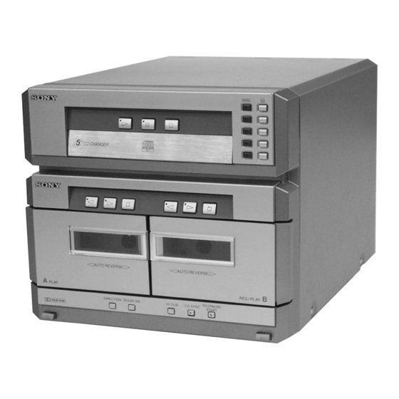
- Page 44 AEP Model UK Model E Model Australian Model Tourist Model HTC-NX1 is the CD player and Tape Deck section in MHC-NX1/NX3AV. Dolby noise reduction manufactured under license Model Name Using Similar Mechanism HCD-MD555 from Dolby Laboratories Licensing Corporation. CD Mechanism Type CDM53D-K1BD33 “DOLBY”...
- Page 45 SUR LES DIAGRAMMES SCHÉMATIQUES ET LA LISTE DES PIÈCES SONT CRITIQUES POUR LA SÉCURITÉ DE FONCTIONNEMENT. NE REMPLACER CES COM- POSANTS QUE PAR DES PIÈCES SONY DONT LES NUMÉROS SONT DONNÉS DANS CE MANUEL OU DANS LES SUPPLÉMENTS PUBLIÉS PAR SONY.
- Page 46 • As this set has not own power supply, it does not operate inde- attachment to power feed jig pendently. Therefore, during servicing, connect it to the Pre- Main amplifier and Tuner Unit (STR-NX1/NX3) of MHC-NX1/ Relay connector jig NX3AV.
- Page 47 OPTICAL PICK-UP CLEANING 1 Remove the case. (Refer to disassembly page 8) 2 four screws (BVTP M2.6) 3 Open the magnet ass’y. 4 Cleaning the Note 1: In cleaning the lens, do not apply an excessive force. optical pick-up. As the optical pick-up is vulnerable, application of excessive force could damage the lens holder.
-
Page 48: General
SECTION 2 GENERAL • LOCATION OF CONTROLS – Front Panel – 1 2 3 1 G (CD) button and indicator 2 S (CD) button and indicator 3 s (CD) button 4 DISC1 to 5 buttons and indicators 5 A (DISC1 to 5) buttons and indicators 6 g (DECK A) button and indicator 7 G (DECK A) button and indicator 8 s (DECK A) button... -
Page 49: Disassembly
SECTION 3 DISASSEMBLY Note: Follow the disassembly procedure in the numerical order given. CASE 1 screw (BVTP3 3 Remove the case 2 two screws in the arrow A (case 3 TP2) direction. 2 two screws (case 3 TP2) FRONT PANEL SECTION 3 two screws (BVTP3 1 flat cable (17 core) - Page 50 CD MECHANISM DECK SECTION (CDM53D-K1BD33) 4 Remove the CD mechanism deck section (CDM53D-K1BD33) in 3 four screws the arrow A direction. (BVTP3 to fitting base (guide) ass’y, bracket (chassis) and magnet ass’y (page 9) 1 flat cable (17 core) (12 cm) (CN112) 2 connector (CN713) 1 flat cable (19 core)
- Page 51 CD BASE UNIT (BU-K1BD33) 4 CD base unit (BU-K1BD33) 3 compression spring 2 compression spring (black) (silver) 1 two screws 1 two screws (PTPWH M2.6) (PTPWH M2.6) MAIN BOARD 4 Remove the MAIN board in the arrow A direction. 2 two screws (BVTP3 2 two screws (BVTP3...
- Page 52 FITTING BASE (GUIDE) ASS’Y, BRACKET (CHASSIS) AND MAGNET ASS’Y 7 four screws (BVTP M2.6) 5 bracket (chassis) 2 four screws (BVTP M2.6) 4 screw (BVTP M2.6) 6 connector (CN710) 8 magnet ass’y from CD mechanism deck section 4 screw (CDM53D-K1BD3) (BVTP M2.6) (page 7) 3 fitting base...
- Page 53 CHASSIS (MOLD B) SECTION, STOCKER SECTION AND SLIDER (SELECTION) Note: In mounting the parts, refer to page 11 and 12. 6 two screws (PTPWH M2.6) 5 stocker section 7 slider (selection) 8 washer 9 compression 1 three screws spring pulley (LD) (BVTP M2.6) 4 two step screws...
- Page 54 SLIDER (SELECTION) INSTALLATION 6 two screws (PTPWH M2.6) 2 gear (chuking) rotary encoder 5 washer 4 compression spring 7 Insert the slider (selection) into the portion A. Align with the slot of rotary encoder. portion A 3 convex portion of slider (selection) gear (chuking) 1 rotary encoder...
- Page 55 CHASSIS (MOLD B) SECTION INSTALLATION 3 three screws (BVTP M2.6) 2 Insert the gear (eject) 1 Insert the portion A of under the gear (LD chassis (mold B) section deceleration). portion A into the portion B of slider (selection). gear (LD deceleration) portion B of slider (selection)
-
Page 56: Test Mode
SECTION 4 TEST MODE [LED All Lit, Key Check Mode] Procedure: 1. Press the button to turn the power ON. 2. Press three buttons of (DECK B), (DISC 1), and [DISC 5] simultaneously. 3. LEDs are all turned on. Press the (CD) button, and the key check mode is activated. -
Page 57: Mechanical Adjustments
SECTION 5 SECTION 6 MECHANICAL ADJUSTMENTS ELECTRICAL ADJUSTMENTS Precaution TAPE DECK SECTION 0 dB=0.775 V 1. Clean the following parts with a denatured alcohol-moistened swab: 1. Demagnetize the record/playback head with a head demagne- record/playback heads pinch rollers tizer. erase head rubber belts 2. - Page 58 DECK B 2. Turn the adjustment screw and check output peaks. If the peaks Tape Speed Adjustment do not match for L-CH and R-CH, turn the adjustment screw so that outputs match within 1dB of peak. • Execute only if connected to the STR-NX1/NX3 Mode: Playback test tape AUDIO OUT jack...
- Page 59 DECK B REC Bias Adjustment Specified value: AUDIO OUT jack PB level: 47.2 to 53.0 mV (–24.3 to –23.3 dB) Procedure: 1. Mode: Record Adjustment Location: MAIN board AUDIO IN jack – MAIN BOARD (Conductor Side) – 1) 315 Hz 50 mV (–23.8 dB) 2) 10 kHz AF OSC...
-
Page 60: Cd Section
RF LEVEL CHECK CD SECTION Note: oscilloscope 1. CD Block is basically designed to operate without adjustment. There- fore, check each item in order given. BD board 2. Use YEDS-18 disc (3-702-101-01) unless otherwise indicated. 3. Use an oscilloscope with more than 10 M impedance. - Page 61 Connecting points: – BD BOARD (Side B) – – MAIN BOARD (Conductor Side) – IC101 IC102 (VC) (AGCCON) (FEO) SL101 (RF) (ADJ) IC101 (GND) (TEO) TP (VC) TP (FEI)
-
Page 62: Diagrams
SECTION 7 DIAGRAMS 7-1. NOTE FOR PRINTED WIRING BOARDS AND SCHEMATIC DIAGRAMS • Circuit Boards Location (In addition to this, the necessary note is printed in each block) CLAMP MOTOR board Note on Printed Wiring Board: Note on Schematic Diagram: SENSOR 2 board •... - Page 63 HTC-NX1 7-2. PRINTED WIRING BOARD – BD Board – • See page 19 for Circuit Boards Location. (GND) (Page 27) • Semiconductor • Semiconductor Location Location (Side A) (Side B) Ref. No. Location Ref. No. Location Q101 IC101 IC102 IC103...
-
Page 64: Schematic Diagram - Bd Board
HTC-NX1 7-3. SCHEMATIC DIAGRAM – BD Board – • See page 32 for Waveforms. • See page 32 for IC Block Diagrams. (Page 29) • Voltages and waveforms are dc with respect to ground under no-signal conditions. no mark : CD PLAY The components identified by mark 0 or dotted Les composants identifiés par une marque 0 sont line with mark 0 are critical for safety. -
Page 65: Printed Wiring Boards - Cd Motor/Sensor Section
HTC-NX1 7-4. PRINTED WIRING BOARDS – CD MOTOR/SENSOR Section – • See page 19 for Circuit Boards Location. TO OUT SW BOARD TO IN SW BOARD TO CONNECTOR BOARD TO SENSOR BOARD (Page 27) TO CLAMP TO INT/ MOTOR COUNT SW BOARD BOARD TO OUT SW BOARD... - Page 66 HTC-NX1 • Voltages are dc with respect to ground under no-signal conditions. no mark : CD PLAY 7-5. SCHEMATIC DIAGRAM – CD MOTOR/SENSOR Section – • See page 33 for IC Block Diagram. (Page 29) (Page 29)
- Page 67 HTC-NX1 7-6. PRINTED WIRING BOARD – AUDIO Board – • See page 19 for Circuit Boards Location. (Page 27)
-
Page 68: Schematic Diagram - Audio Board
HTC-NX1 7-7. SCHEMATIC DIAGRAM – AUDIO Board – • See page 33 for IC Block Diagram. PB EQ AMP (PLAYBACK) (DECK A) PB LEVEL (L) (DECK A) PB LEVEL (R) (DECK A) PB EQ AMP (DECK B) PB LEVEL (L) (DECK B) A +7.5V PB LEVEL (R) -
Page 69: Printed Wiring Board - Leaf Sw Board
HTC-NX1 7-8. PRINTED WIRING BOARD – LEAF SW Board – • See page 19 for Circuit Boards Location. DECK B DECK A PLUNGER PLUNGER (DECK B PLAY) (DECK B 120/70) (DECK A PLAY) (DECK B HALF) (DECK A REC) (DECK A 120/70) (DECK A HALF) (Page 27) 7-9. -
Page 70: Printed Wiring Board - Main Board
HTC-NX1 7-10. PRINTED WIRING BOARD – MAIN Board – • See page 19 for Circuit Boards Location. (Page 24) (Page 30) (Page 26) (Page 30) (Page 20) (Page 30) (Page 22) (Page 22) • Semiconductor Location Ref. No. Location Ref. No. Location Ref. -
Page 71: Schematic Diagram - Main Board (1/2)
HTC-NX1 7-11. SCHEMATIC DIAGRAM – MAIN Board (1/2) – (Page 25) (Page 26) (Page 29) • Voltages are dc with respect to ground under no-signal conditions. no mark : CD PLAY The components identified by mark 0 or dotted Les composants identifiés par une marque 0 sont ) : TAPE PLAYBACK (DECK A) line with mark 0 are critical for safety. -
Page 72: Schematic Diagram - Main Board (2/2)
HTC-NX1 7-12. SCHEMATIC DIAGRAM – MAIN Board (2/2) – • See page 32 for Waveform. (Page 28) (Page 31) (Page 23) (Page 23) (Page 31) (Page 31) (Page 21) • Voltages and waveforms are dc with respect to ground ] : TAPE PLAYBACK (DECK B) under no-signal conditions. -
Page 73: Printed Wiring Boards - Panel Section
HTC-NX1 7-13. PRINTED WIRING BOARDS – PANEL Section – • See page 19 for Circuit Boards Location. (Page 27) • Semiconductor Location – PANEL Board – Ref. No. Location Ref. No. Location D223 D201 D202 D224 D203 D225 D204 D205 Q201 D206 Q202... -
Page 74: Schematic Diagram - Panel Section
HTC-NX1 7-14. SCHEMATIC DIAGRAM – PANEL Section – (Page 29) (Page 29) (Page 29) • Voltages are dc with respect to ground under no-signal conditions. no mark : CD PLAY... - Page 75 • Waveforms • IC Block Diagrams – BD Board – – MAIN Board – – BD Board – IC101 CXD2587Q 5 IC101 yh (XTAI) 1 IC101 qd (XOUT) 1 IC103 qh (RF O) (CD Play Mode) Approx. 3 Vp-p 1.9 Vp-p 1.2 Vp-p ERROR DIGITAL...
- Page 76 IC103 CXA2568M-T6 HOLD APC PD AMP LC/PD APC LD AMP – LD ON – – – HOLD SW AGC CONT AGC VTH 50 A – RF BOT – – – – RFTC RF SUMMING AMP RF EQ AMP RF I RF O –...
-
Page 77: Ic Pin Function Description
7-15. IC PIN FUNCTION DESCRIPTION MAIN BOARD IC101 M30622MA-A13FP (SYSTEM CONTROLER (CD MECHANISM CONTROL)) Pin No. Pin Name Description CD DATA Serial data output to the CXD2587Q (IC101) on the CD block CD CLK Serial data transfer clock signal output to the CXD2587Q (IC101) on the CD block Serial data latch pulse output to the CXD2587Q (IC101) on the CD block Reset signal output to the CXD2587Q (IC101) and BA5974FP (IC102) on the CD block XRST... - Page 78 Pin No. Pin Name Description LED A CDPL LED drive signal output of the G (CD) indicator (D211) “L”: LED on LED A RECP LED drive signal output terminal Not used (open) LED R RECP LED drive signal output of the REC PAUSE/START indicator (D217) “H”: LED on LED SYNC LED drive signal output of the CD SYNC indicator (D216)
- Page 79 Pin No. Pin Name Description CAPM-CNT2 Capstan motor (M1) drive signal output terminal “H” active *3 CAPM-CNT1 Capstan motor (M1) drive signal output terminal “H” active *3 High/normal speed selection signal output of the capstan motor (M1) CAP-M-H/L “L”: normal speed, “H”: high speed Whether a music is present or not from the HA12215F (IC301) is detected an automatic music AMS-IN sensor “L”: music is present, “H”: music is not present...
-
Page 80: Exploded Views
SECTION 8 EXPLODED VIEWS NOTE: • -XX and -X mean standardized parts, so they • Items marked “*” are not stocked since they The components identified by mark 0 or dotted line with mark may have some difference from the original are seldom required for routine service. - Page 81 (2) FRONT PANEL SECTION supplied supplied supplied supplied TCM-230AWR2 supplied supplied supplied supplied supplied Ref. No. Part No. Description Remark Ref. No. Part No. Description Remark X-4951-821-1 HOLDER (B) ASSY, CASSETTE 1-674-773-11 PANEL TC-B BOARD 4-221-448-01 SPRING (HOLDER B) 4-221-443-01 BUTTON, EJECT 4-221-447-01 SPRING (HOLDER A) 1-773-004-11 WIRE (FLAT TYPE) (15 CORE) X-4951-820-1 HOLDER (A) ASSY, CASSETTE...
- Page 82 (3) CD MECHANISM DECK SECTION-1 (CDM53D-K1BD33) M702 Ref. No. Part No. Description Remark Ref. No. Part No. Description Remark 4-218-253-01 SCREW (M2.6), +BVTP 4-214-129-01 COVER * 152 1-671-508-21 LOAD MOTOR BOARD 4-211-235-01 BELT (COMMUNICATION) 4-220-261-01 GEAR (EJECT) 4-211-236-01 BELT (LOADING) * 154 1-671-502-21 INT/COUNT SW BOARD 4-220-278-01 PULLEY (MODE)
- Page 83 (4) CD MECHANISM DECK SECTION-2 (CDM53D-K1BD33) not supplied not supplied S707 not supplied M701 BU-K1BD33 supplied supplied Ref. No. Part No. Description Remark Ref. No. Part No. Description Remark 4-985-672-01 SCREW (+PTPWH M2.6), FLOATING 4-220-275-01 GEAR (CHUCKING) 4-220-933-01 INSULATOR 4-211-245-01 SPRING, COMPRESSION 4-213-487-53 TRAY (SUB) * 226 1-671-507-21 CLAMP MOTOR BOARD...
- Page 84 (5) CD BASE UNIT SECTION (BU-K1BD33) not supplied not supplied not supplied M101 M102 The components identified by Les composants identifiés par une mark 0 or dotted line with marque 0 sont critiques pour la mark 0 are critical for safety. sécurité.
- Page 85 (6) TAPE MECHANISM DECK SECTION-1 (TCM-230AWR2) HP101 HRPE101 Ref. No. Part No. Description Remark Ref. No. Part No. Description Remark 3-376-464-11 SCREW (+PTT 2.6X6), GROUND POINT 3-016-565-01 BASE (PINCH LEVER REV) 3-036-914-01 RIVET 3-026-892-01 SPRING (CASSETTE), LEAF 3-016-574-11 SPRING (HEAD), TENSION * 409 A-2007-731-A AUDIO BOARD, COMPLETE X-3374-156-4 PINCH LEVER (REV) ASSY...
- Page 86 (7) TAPE MECHANISM DECK SECTION-2 (TCM-230AWR2) Ref. No. Part No. Description Remark Ref. No. Part No. Description Remark * 451 X-3374-214-4 CHASSIS ASSY, MAIN A-2004-629-A MECHANICAL BLOCK ASSY 3-016-570-01 BELT (CAPSTAN) 3-016-566-01 SLIDER, REVERSE 3-016-569-01 BELT (TENSION) * 461 A-2007-732-A LEAF SW BOARD, COMPLETE 3-017-360-01 BRACKET (MOTOR) 3-016-575-11 SPRING, TORSION X-3376-497-3 FLYWHEEL (FWD) ASSY...
-
Page 87: Electrical Parts List
SECTION 9 AUDIO ELECTRICAL PARTS LIST NOTE: • Due to standardization, replacements in the • Items marked “*” are not stocked since they The components identified by mark 0 or dotted line with mark parts list may be different from the parts speci- are seldom required for routine service. - Page 88 AUDIO Ref. No. Part No. Description Remark Ref. No. Part No. Description Remark R612 1-249-409-11 CARBON 1/4W 0 R621 1-212-851-00 FUSIBLE 1/4W F C157 1-163-009-11 CERAMIC CHIP 0.001uF 0 R622 1-212-851-00 FUSIBLE 1/4W F C159 1-163-019-00 CERAMIC CHIP 0.0068uF 10% R623 1-249-432-11 CARBON 1/4W...
- Page 89 CLAMP MOTOR CONNECTOR IN SW INT/COUNT SW LEAF SW Ref. No. Part No. Description Remark Ref. No. Part No. Description Remark < RESISTOR > R147 1-216-069-00 METAL CHIP 6.8K 1/10W R148 1-216-001-00 METAL CHIP 1/10W R707 1-249-424-11 CARBON 3.9K 1/4W R149 1-216-001-00 METAL CHIP 1/10W...
- Page 90 LEAF SW LOAD MOTOR MAIN Ref. No. Part No. Description Remark Ref. No. Part No. Description Remark R1008 1-249-417-11 CARBON 1/4W C112 1-126-925-11 ELECT 470uF C118 1-216-916-11 ELECT 1000uF 6.3V < VARIABLE RESISTOR > C119 1-161-494-00 CERAMIC 0.022uF RV1001 1-241-785-11 RES, ADJ, CARBON 10K C120 1-164-159-11 CERAMIC 0.1uF...
- Page 91 MAIN Ref. No. Part No. Description Remark Ref. No. Part No. Description Remark C871 1-164-159-11 CERAMIC 0.1uF Q331 8-729-118-00 TRANSISTOR 2SB1116-TP-LK C872 1-126-925-11 ELECT 470uF Q332 8-729-900-80 TRANSISTOR BA1A4M-TP C873 1-104-665-11 ELECT 100uF Q333 8-729-118-00 TRANSISTOR 2SB1116-TP-LK C876 1-104-665-11 ELECT 100uF Q334 8-729-900-80 TRANSISTOR BA1A4M-TP...
- Page 92 MAIN OUT SW PANEL Ref. No. Part No. Description Remark Ref. No. Part No. Description Remark R142 1-249-429-11 CARBON 1/4W R334 1-249-415-11 CARBON 1/4W R143 1-249-429-11 CARBON 1/4W R335 1-249-421-11 CARBON 2.2K 1/4W R144 1-249-411-11 CARBON 1/4W R145 1-249-429-11 CARBON 1/4W R336 1-249-437-11 CARBON...
- Page 93 PANEL Ref. No. Part No. Description Remark Ref. No. Part No. Description Remark R213 1-249-407-11 CARBON 1/4W < LED > R214 1-249-407-11 CARBON 1/4W R215 1-249-407-11 CARBON 1/4W D201 8-719-076-15 LED SELS6B14C-TP6 (KEY ILLUMINATION) D202 8-719-076-15 LED SELS6B14C-TP6 (KEY ILLUMINATION) R216 1-249-410-11 CARBON 1/4W...
- Page 94 PANEL TC-A PANEL TC-B SENSOR SENSOR 2 Ref. No. Part No. Description Remark Ref. No. Part No. Description Remark 1-674-773-11 PANEL TC-A BOARD 1-773-170-11 WIRE (FLAT TYPE) (21 CORE) 1-773-004-11 WIRE (FLAT TYPE) (15 CORE) **************** < RESISTOR > 1-773-044-11 WIRE (FLAT TYPE) (17 CORE) (16cm) 0 253 8-820-026-03 OPTICAL PICK-UP KSM-213BFN/C2NP R246...
- Page 95 HTC-NX1 Sony Corporation 9-928-981-11 99H0588-1 Home Audio Company Printed in Japan © 1999. 8 Published by Quality Assurance Dept.
- Page 96 SS-NX1 SERVICE MANUAL US Model Canadian Model AEP Model UK Model E Model Australian Model Tourist Model Photo: AEP model • SS-NX1 is the speaker system in MHC-NX1/NX3AV. SPECIFICATIONS SPEAKER SYSTEM MICROFILM...
-
Page 97: Exploded View And Parts List
1-769-433-21 CORD, SPEAKER (AEP, UK) A-4411-715-A CABINET ASSY, SPEAKER 3-867-790-11 MANUAL, INSTRUCTION (ENGLISH, FRENCH, GERMAN, SWEDISH, RUSSIAN) (AEP, UK) 1-761-223-11 MOUNTED PC BOARD Sony Corporation 9-928-982-11 99H051688-1 Home Audio Company Printed in Japan © 1999. 8 Published by Quality Assurance Dept.