Table of Contents
Advertisement
Advertisement
Table of Contents

Related Manuals for Asus K8N-VM


Summary of Contents for Asus K8N-VM
- Page 1 K8N-VM...
- Page 2 Product warranty or service will not be extended if: (1) the product is repaired, modified or altered, unless such repair, modification of alteration is authorized in writing by ASUS; or (2) the serial number of the product is defaced or missing.
-
Page 3: Table Of Contents
Contents Notices ....................vi Safety information ................vii k8N-VM specifications summary ............viii Chapter 1: Product introduction Welcome! ................1-2 Package contents ..............1-2 Special features ..............1-2 1.3.1 Product highlights ........... 1-2 1.3.2 Innovative ASUS features ........1-4 Before you proceed .............. 1-5 Motherboard overview ............ - Page 4 Creating a bootable floppy disk ......2-2 2.1.2 ASUS EZ Flash utility ..........2-3 2.1.3 AFUDOS utility ............2-4 2.1.4 ASUS CrashFree BIOS 2 utility ........ 2-6 2.1.5 ASUS Update utility ..........2-8 BIOS setup program ............2-11 2.2.1 BIOS menu screen ..........2-12 2.2.2...
- Page 5 Chapter 3: Software support Installing an operating system ..........3-2 Support CD information ............3-2 3.2.1 Running the support CD .......... 3-2 3.2.2 Drivers menu ............3-3 3.2.3 Utilities menu ............3-4 3.2.4 Manual menu ............3-5 3.2.5 ASUS Contact information ........3-6...
-
Page 6: Notices
Notices Federal Communications Commission Statement This device complies with Part 15 of the FCC Rules. Operation is subject to the following two conditions: • This device may not cause harmful interference, and • This device must accept any interference received including interference that may cause undesired operation. -
Page 7: Safety Information
Safety information Electrical safety • To prevent electrical shock hazard, disconnect the power cable from the electrical outlet before relocating the system. • When adding or removing devices to or from the system, ensure that the power cables for the devices are unplugged before the signal cables are connected. -
Page 8: K8N-Vm Specifications Summary
K8N-VM specifications summary Socket 754 for AMD Athlon™ 64/ Sempron™ processors Supports AMD 64 architecture that enables simultaneous 32-bit and 64-bit architecture Supports AMD Cool ʻnʼ Quiet™ Technology Chipset Northbridge: NVIDIA GeForce 6100 ® Southbridge: NVIDIA nForce 410 ® 1600 MT/s... - Page 9 K8N-VM specifications summary BIOS features 4 Mb Flash ROM, AMI BIOS, PnP, DMI2.0, WfM2.0, ACPI 2.0a, SM BIOS 2.3 Internal 1 x Front panel audio connector connectors 1 x CD in audio connector 1 x CPU fan connector 1 x S/PDIF Out connector 2 x USB 2.0 connectors for four additional USB 2.0 ports...
-
Page 11: Chapter 1: Product Introduction
This chapter describes the motherboard features and the new technologies it supports. Product introduction... -
Page 12: Welcome
® The motherboard delivers a host of new features and latest technologies, making it another standout in the long line of ASUS quality motherboards! Before you start installing the motherboard, and hardware devices on it, check the items in your package with the list below. - Page 13 12 Mbps bandwidth on USB 1.1 to a fast 480 Mbps on USB 2.0. USB 2.0 is backward compatible with USB 1.1. See pages 1-19, 1-22 and 1-25 for details. ASUS K8N-VM...
-
Page 14: Innovative Asus Features
Innovative ASUS features ASUS EZ Flash BIOS With the ASUS EZ Flash, you can easily update the system BIOS even before loading the operating system. No need to use a DOS-based utility or boot from a floppy disk. See page 2-3 for details. -
Page 15: Before You Proceed
This is a reminder that you should shut down the system and unplug the power cable before removing or plugging in any motherboard component. The illustration below shows the location of the onboard LED. SB_PWR K8N-VM Standby Powered K8N-VM Onboard LED Power ASUS K8N-VM... -
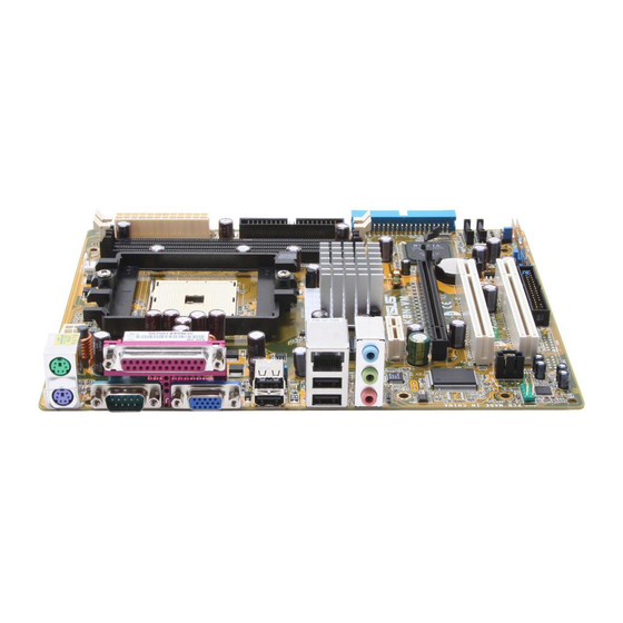
Page 16: Motherboard Overview
USB1 USB2 Bottom: Top: USB3 RJ-45 4Mb Flash USB4 nVidia GeForce 6100 Top:Line In Center:Line Out Below:Mic In Realtek PCIEX1_1 K8N-VM PCIEX16 nVidia Super I/O nForce 410 CR2032 3V PCI1 Lithium Cell CMOS Powe SATA2 AAFP SB_PWR PCI2 SATA1 Audio... -
Page 17: Placement Direction
Place six (6) screws into the holes indicated by circles to secure the motherboard to the chassis. Do not overtighten the screws! Doing so can damage the motherboard. Place this side towards the rear of the chassis K8N-VM ASUS K8N-VM... -
Page 18: Layout Contents
1.5.4 Layout contents Slots Page 1. PCI slots 1-17 2. PCI Express x 1 slot 1-17 3. PCI Express x 16 slot 1-17 Jumpers Page 1. Clear RTC RAM (CLRTC) 1-18 2. USB Device wake-up (3-pin USBPW1234, USBPW5678) 1-19 3. Keyboard power (3-pin KBPWR) 1-20 Rear panel connectors Page... -
Page 19: Central Processing Unit (Cpu)
Installing the CPU Follow these steps to install a CPU. Locate the 754-pin ZIF socket on the motherboard. K8N-VM K8N-VM CPU Socket 754 Unlock the socket by pressing the lever sideways, then lift it up to a 90°-100° angle. Socket Lever Make sure that the socket lever is lifted up to 90°-100°... - Page 20 Connect the CPU fan cable to the CPU_FAN connector on the motherboard. CPU_FAN K8N-VM K8N-VM CPU Fan Connector Do not forget to connect the CPU fan connector! Hardware monitoring errors can occur if you fail to plug this connector. 1-10...
-
Page 21: System Memory
The motherboard comes with two 184-pin Double Data Rate (DDR) Dual Inline Memory Modules (DIMM) sockets. The following figure illustrates the location of the sockets: K8N-VM K8N-VM 184-pin DDR DIMM Sockets 1.7.2 Memory configurations You may install 128 MB, 256 MB, 512 MB, and 1 GB unbuffered ECC/non-ECC DDR DIMMs into the DIMM sockets using the memory configurations in this section. - Page 22 DDR400 Qualified Vendors List DIMM support Size Vendor Mode Brand Side(s) Component 256MB Kingston KVR333X64C25/256 Kingston D3208DH1T-6 256MB Kingston KVR333X64C25/256 Hynix HY5DU56822BT-J 256MB Kingston KVR333X64C25/256 Hynix HY5DU56822BT-D43 5126MB Kingston KVR333X64C25/512 Kingston D3208DH1T-6 5126MB Kingston KVR400X64C3A/512 Hynix HY5DU56822BT-D43 5126MB Kingston KVR400X64C3A/512 Kingston D3208DH1T-5 5126MB...
- Page 23 - supports one module inserted in any slot as Single-channel memory configuration. supports on pair of modules inserted into the slots as Single-channel memory configuration. Visit the ASUS website (www.asus.com) for the latest DDR 400 Qualified Vendors List. ASUS K8N-VM 1-13...
-
Page 24: Installing A Dimm
1.7.3 Installing a DIMM Make sure to unplug the power supply before adding or removing DIMMs or other system components. Failure to do so may cause severe damage to both the motherboard and the components. Unlock a DIMM socket by DDR DIMM notch pressing the retaining clips outward. -
Page 25: Expansion Slots
Turn on the system and change the necessary BIOS settings, if any. See Chapter 2 for information on BIOS setup. Assign an IRQ to the card. Refer to the tables on the next page. Install the software drivers for the expansion card. ASUS K8N-VM 1-15... -
Page 26: Standard Interrupt Assignments
Standard interrupt assignments Priority Standard Function System Timer Keyboard Controller – Re-direct to IRQ#9 IRQ holder for PCI steering* Communications Port (COM1)* IRQ holder for PCI steering* Floppy Disk Controller Printer Port (LPT1)* System CMOS/Real Time Clock IRQ holder for PCI steering* IRQ holder for PCI steering* IRQ holder for PCI steering* PS/2 Compatible Mouse Port*... -
Page 27: Pci Slots
PCI Express x1 slot. 1.8.5 PCI Express x16 slot This motherboard has supports PCI Express x16 graphic cards that comply with PCI Express specifications. The figure shows a graphics card installed on the PCI Express x16 slot. ASUS K8N-VM 1-17... -
Page 28: Jumpers
Normal Clear CMOS (Default) K8N-VM Clear RTC RAM You do not need to clear the RTC when the system hangs due to overclocking. For system failure due to overclocking, use the C.P.R. (CPU Parameter Recall) feature. Shut down and reboot the system so the BIOS can automatically reset parameter settings to default values. -
Page 29: Usb Device Wake-Up (3-Pin Usbpw1234, Usbpw)
+5VSB (Default) K8N-VM USBPW5678 +5VSB (Default) K8N-VM USB Device Wake-Up • The USB device wake-up feature requires a power supply that can provide 500mA on the +5VSB lead for each USB port; otherwise, the system will not power up. •... -
Page 30: Keyboard Power (3-Pin Kbpwr)
(the default is the Space Bar). This feature requires an ATX power supply that can supply at least 500 mA on the +5VSB lead, and a corresponding setting in the BIOS. KBPWR +5VSB (Default) K8N-VM K8N-VM Keyboard Power Setting 1-20 Chapter 1: Product introduction... -
Page 31: 1.10 Connectors
2, 4, or 6,-channel configuration. Audio 2, 4, or 6-channel configuration Port Headset 4-speaker 6-speaker 2-speaker Light Blue Line In Surround Out Surround Out Lime Line Out Front Speaker Out Front Speaker Out Pink Mic In Center/Bass ASUS K8N-VM 1-21... -
Page 32: 1.10.2 Internal Connectors
Pin 5 on the connector is removed to prevent incorrect cable connection when using an FDD cable with a covered Pin 5. FLOPPY NOTE: Orient the red markings on the floppy ribbon cable to PIN 1. PIN1 K8N-VM K8N-VM Floppy Disk Drive Connector 1-22 Chapter 1: Product introduction... -
Page 33: Ide Connectors (40-1 Pin Pri_Ide, Sec_Ide)
If any device jumper is set as “Cable-Select,” make sure all other device jumpers have the same setting. PIN1 PIN 1 K8N-VM NOTE: Orient the red markings K8N-VM IDE Connectors (usually zigzag) on the IDE ribbon cable to PIN 1. ASUS K8N-VM 1-23... -
Page 34: Serial Ata Connectors (7-Pin Sata1, Sata)
MB/s data transfer rate while Serial ATA II allows up to 300 MB/s data transfer rate, faster than the standard parallel ATA with 133 MB/s (Ultra DMA/133) SATA2 K8N-VM SATA1 K8N-VM SATA Connectors Install the Windows 2000 Service Pack 4 or the Windows XP Service ® ®... -
Page 35: Digital Audio Connector (4-1 Pin Spdif_Out)
The S/PDIF module is purchased separately. SPDIFOUT K8N-VM SPDIF_OUT K8N-VM Digital Audio Connector USB connectors (10-1 pin USB56, USB78) These connectors are for USB 2.0 ports. Connect the USB module cable to any of these connectors, then install the module to a slot opening at the back of the system chassis. -
Page 36: Front Panel Audio Connector (10-1 Pin Aafp)
Azalia-compliant pin definition Legacy AC’97-complian t pin definition K8N-VM AAFP K8N-VM Analog Front Panel Connector • We recommend that you connect a high-definition front panel audio module to this connector to avail of the motherboard high-definition audio capability. • If you want to connect a high-definition front panel audio module to this connector, make sure that the Onboard AUDIO item in the BIOS is set to [Enabled]. -
Page 37: Atx Power Connectors (24-Pin Eatxpwr, 4-Pin Atx12V)
+5 Volts +12 Volts +5V Standby +5 Volts -5 Volts Power OK Ground Ground K8N-VM Ground +5 Volts Ground Ground +5 Volts PSON# Ground Ground +3 Volts -12 Volts +3 Volts +3 Volts K8N-VM ATX Power Connectors ASUS K8N-VM 1-27... -
Page 38: System Panel Connector (20-1 Pin Panel)
K8N-VM RESET IDE_LED PWRSW Requires an ATX power supply. K8N-VM System Panel Connector The sytem panel connector is color-coded for easy connection. Refer to the connector description below for details. • System power LED (Green 3-pin PLED) This 3-pin connector is for the system power LED. Connect the chassis power LED cable to this connector. -
Page 39: Chapter 2: Bios Setup
This chapter tells how to change the system settings through the BIOS Setup menus. Detailed descriptions of the BIOS parameters are also provided. BIOS setup... -
Page 40: Managing And Updating Your Bios
The following utilities allow you to manage and update the motherboard Basic Input/Output System (BIOS) setup. ASUS EZ Flash (Updates the BIOS using a floppy disk during POST.) ASUS AFUDOS (Updates the BIOS in DOS mode using a bootable floppy disk.) -
Page 41: Asus Ez Flash Utility
2.1.2 ASUS EZ Flash utility The ASUS EZ Flash feature allows you to update the BIOS without having to go through the long process of booting from a floppy disk and using a DOS-based utility. The EZ Flash utility is built-in the BIOS chip so it is accessible by pressing <Alt>... -
Page 42: Afudos Utility
2.1.3 AFUDOS utility The AFUDOS utility allows you to update the BIOS file in DOS environment using a bootable floppy disk with the updated BIOS file. This utility also allows you to copy the current BIOS file that you can use as backup when the BIOS fails or gets corrupted during the updating process. -
Page 43: Updating The Bios File
Updating the BIOS file To update the BIOS file using the AFUDOS utility: Visit the ASUS website (www.asus.com) and download the latest BIOS file for the motherboard. Save the BIOS file to a bootable floppy disk. Write the BIOS filename on a piece of paper. You need to type the exact BIOS filename at the DOS prompt. -
Page 44: Asus Crashfree Bios 2 Utility
2.1.4 ASUS CrashFree BIOS 2 utility The ASUS CrashFree BIOS 2 is an auto recovery tool that allows you to restore the BIOS file when it fails or gets corrupted during the updating process. You can update a corrupted BIOS file using the motherboard support CD or the floppy disk that contains the updated BIOS file. -
Page 45: Recovering The Bios From The Support Cd
Restart the system after the utility completes the updating process. The recovered BIOS may not be the latest BIOS version for this motherboard. Visit the ASUS website (www.asus.com) to download the latest BIOS file. ASUS K8N-VM... -
Page 46: Asus Update Utility
2.1.5 ASUS Update utility The ASUS Update is a utility that allows you to manage, save, and update the motherboard BIOS in Windows environment. The ASUS Update utility ® allows you to: • Save the current BIOS file • Download the latest BIOS file from the Internet •... -
Page 47: Updating The Bios Through The Internet
To update the BIOS through the Internet: Launch the ASUS Update utility from the Windows desktop by clicking ® Start > Programs > ASUS > ASUSUpdate > ASUSUpdate. The ASUS Update main window appears. Select Update BIOS from Select the ASUS FTP site... -
Page 48: Updating The Bios Through A Bios File
To update the BIOS through a BIOS file: Launch the ASUS Update utility from the Windows desktop by ® clicking Start > Programs > ASUS > ASUSUpdate > ASUSUpdate. The ASUS Update main window appears. Select Update BIOS from a file option from the drop-down menu, then click Next. -
Page 49: Bios Setup Program
The BIOS setup screens shown in this section are for reference purposes only, and may not exactly match what you see on your screen. • Visit the ASUS website (www.asus.com) to download the latest BIOS file for this motherboard. ASUS K8N-VM 2-11... -
Page 50: Bios Menu Screen
[1.44M, 3.5 in] select a field. Use [+] or [-] to Primary IDE Master [ST320413A] configure system time. Primary IDE Slave [ASUS CD-S520/A] Secondary IDE Master [Not Detected] Secondary IDE Slave [Not Detected] First SATA [Not Detected] Second SATA [Not Detected] <->... -
Page 51: Menu Items
Save and Exit /<Page Down> keys to display the Exit other items on the screen. Pop-up window 2.2.9 General help At the top right corner of the menu screen is a brief description of the selected item. ASUS K8N-VM 2-13... -
Page 52: Main Menu
Legacy Diskette A [1.44M, 3.5 in] Use [+] or [-] to configure system time. Primary IDE Master [ST320413A] Primary IDE Slave [ASUS CD-S520/A] Secondary IDE Master [Not Detected] Secondary IDE Slave [Not Detected] First SATA [Not Detected] <-> Select Screen... -
Page 53: Primary And Secondary Ide Master/Slave; First And Second Sata
When set to [Disabled], the data transfer from and to the device occurs one sector at a time. Configuration options: [Disabled] [Auto] ASUS K8N-VM 2-15... -
Page 54: Ide Configuration
PIO Mode [Auto] Selects the PIO mode. Configuration options: [Auto] [0] [1] [2] [3] [4] DMA Mode [Auto] Selects the DMA mode. Configuration options: [Auto] SMART Monitoring [Auto] Sets the Smart Monitoring, Analysis, and Reporting Technology. Configuration options: [Auto] [Disabled] [Enabled] 32Bit Data Transfer [Disabled] Enables or disables 32-bit data transfer. -
Page 55: System Information
Usable Size : 192MB ↑↓ Select Item Change Field Select Field General Help Save and Exit Exit AMI BIOS Displays the auto-detected BIOS information. Processor Displays the auto-detected CPU specification. System Memory Displays the auto-detected system memory. ASUS K8N-VM 2-17... -
Page 56: Advanced Menu
Advanced menu The Advanced menu items allow you to change the settings for the CPU and other system devices. Take caution when changing the settings of the Advanced menu items. Incorrect field values can cause the system to malfunction. AMD Cool ‘n’ Quiet Configuration JumperFree Configuration Configure AMD Cool CPU Configuration... -
Page 57: Jumperfree Configuration
PCI bus. The value of this item is auto-detected by the BIOS. Use the <+> and <-> keys to adjust the CPU frequency. You can also type the desired CPU frequency using the numeric keypad. The values range from 200 to 240. ASUS K8N-VM 2-19... -
Page 58: Cpu Configuration
2.4.3 CPU Configuration The items in this menu show the CPU-related information auto-detected by BIOS. CPU Configuration Module Version: 14.06 Physical Count: 1 Logical Count : 1 AMD Athlon(tm) 64 Processor 3200+ Revision: C0 Cache L1: 64KB Cache L2: 1024KB Speed : 2000MHz Current FSB Multiplier: 10x... -
Page 59: Northbridge Configuration
Memory Configuration Memclock Mode [Auto] Auto MCT Timing Mode [Auto] User Config Mode [Manual] Manual Read Preamble [ 9.5ns] Asyc Latency [11.0ns] CMD-ADDR Timing Mode [2T] Bank Interleaving [Auto] Burst Length [4 Beats] Software Memory Hole [Enabled] ASUS K8N-VM 2-21... - Page 60 Memclock Mode [Auto] Sets the memory clock mode. Configuration options: [Auto] [Limit] The following item appears when the Memclock Mode item is set to [Limit]. Memclock Value [100MHz] Configuration options: [100MHz] [133MHz] [166MHz] [183MHz] [200MHz] MCT Timing Mode [Auto] Sets the MCT Timing mode. Configuration options: [Auto] [Manual] The following item appears when the MCT Time Mode item is set to [Manual].
- Page 61 Enables or disables the MCA DRAM ECC logging. Configuration options: [Disabled] [Enabled] ECC Chip Kill [Disabled] Enables or disables the ECC Chip Kill function. Configuration options: [Disabled] [Enabled] DRAM SCRUB REDIRECT [Disabled] Enables or disables the DRAM SCRUB REDIRECT. Configuration options: [Disabled] [Enabled] ASUS K8N-VM 2-23...
- Page 62 DRAM BG SCRUB [Disabled] Disables or sets the DRAM BG SCRUB. Configuration options: [Disabled] [40ns] [80ns] [160ns] [320ns] [640ns] [1.28us] [2.56us] [5.12us] [10.2us] [20.5us] [41.0us] [81.9us] [163.8us] [327.7us] [655.4us] [1.31ms] [2.62ms] [5.24ms] [10.49ms] [20.97ms] [42.00ms] [84.00ms] L2 Cache BG Scrub [Disabled] Disables or sets the L2 Cache BG Scrub.
- Page 63 PCI Spread Spectrum [Center Spread] Disabled HT Soread Spectrum [Center Spread] Center Spread Down Spread PCI Spread Spectrum [Center Spread] Configuration options: [Disabled] [Center Spread] [Down Spread] HT Spread Spectrum [Center Spread] Configuration options: [Disabled] [Center Spread] [Down Spread] ASUS K8N-VM 2-25...
- Page 64 Hyper Transport Geforce 6100 Configuration Options Hyper Transport Geforce 6100 Configuration LDT(K8) to Geforce 6100(NB) Frequency [800 MHz] PCI-> PCIE->IGP LDT(K8) to Geforce 6100(NB) LinkWidth [Auto] IGP-> PCIE->PCI Hyper Transport nForce 410 Configuration nForce 410 to Geforce 6100(NB) Frequency [800 MHz] nForce 410 to Geforce 6100(NB) LinkWidth [8↑8↓] Hyper Transport Geforcec 6100 Configuration...
-
Page 65: Onboard Devices Configuration
Configuration options: [Enabled] [Disabled] Onboard LAN [Enabled] Allows you to enable or disable the onboard LAN. Configuration options: [Enable] [Disabled] Onboard LAN Boot ROM [Disabled] Allows you to enable or disable the onboard LAN boot ROM. Configuration options: [Disabled] [Enabled] ASUS K8N-VM 2-27... -
Page 66: Pci Pnp
2.4.6 PCI PnP The PCI PnP menu items allow you to change the advanced settings for PCI/PnP devices. The menu includes setting IRQ and DMA channel resources for either PCI/PnP or legacy ISA devices, and setting the memory size block for legacy ISA devices. -
Page 67: Usb Configuration
Allows you to set the USB 2.0 controller mode to HiSpeed (480 Mbps) or FullSpeed (12 Mbps). Configuration options: [FullSpeed] [HiSpeed] BIOS EHCI Hand-Off [Enabled] Allows you to enable support for operating systems without an EHCI hand-off feature. Configuration options: [Disabled] [Enabled] ASUS K8N-VM 2-29... -
Page 68: Power Menu
Power menu The Power menu items allow you to change the settings for the Advanced Power Management (APM). Select an item then press <Enter> to display the configuration options. BIOS SETUP UTILITY Main Advanced Power Boot Exit Suspend Mode [Auto] Select the ACPI state ACPI 2.0 Support [Enabled]... -
Page 69: Apm Configuration
Allows you to enable or disable RTC to generate a wake event. When this item is set to Enabled, the items RTC Alarm Date, RTC Alarm Hour, RTC Alarm Minute, and RTC Alarm Second appear with set values. Configuration options: [Disabled] [Enabled] ASUS K8N-VM 2-31... -
Page 70: Hardware Monitor
Power On By PS/2 Keyboard [Disabled] When set to [Enabled], this parameter allows you to use the PS/2 keyboard to turn on the system. This feature requires an ATX power supply that provides at least 1A on the +5VSB lead. Configuration options: [Disabled] [Enabled] Power On By PS/2 Mouse [Disabled] When set to [Enabled], this parameter allows you to use the PS/2 mouse... - Page 71 (RPM). If the fan is not connected to the motherboard, the field shows N/A. VCORE Voltage, 3.3V Voltage, 5V Voltage, 12V Voltage The onboard hardware monitor automatically detects the voltage output through the onboard voltage regulators. ASUS K8N-VM 2-33...
-
Page 72: Boot Menu
Specifies the boot sequence from the 1st Boot Device [1st FLOPPY DRIVE] availabe devices. 2nd Boot Device [PM-ST320410A] 3rd Boot Device [PS-ASUS CD-S520/A] A device enclosed in parenthesis has been disabled in the corresponding menu. Select Screen Select Item Change Option... -
Page 73: Boot Settings Configuration
This allows you to enable or disable the full screen logo display feature. Configuration options: [Disabled] [Enabled] Set this item to [Enabled] to use the ASUS MyLogo2™ feature. Add On ROM Display Mode [Force BIOS] Sets the display mode for option ROM. -
Page 74: Security
Hit ʻDELʼ Message Display [Enabled] When set to Enabled, the system displays the message “Press DEL to run Setup” during POST. Configuration options: [Disabled] [Enabled] Interrupt 19 Capture [Disabled] When set to [Enabled], this function allows the option ROMs to trap Interrupt 19. -
Page 75: Change User Password
Change User Password Select this item to set or change the user password. The User Password item on top of the screen shows the default Not Installed. After you set a password, this item shows Installed. ASUS K8N-VM 2-37... -
Page 76: Exit Menu
To set a User Password: Select the Change User Password item and press <Enter>. On the password box that appears, type a password composed of at least six letters and/or numbers, then press <Enter>. Confirm the password when prompted. The message “Password Installed” appears after you set your password successfully. -
Page 77: Discard Changes
Setup menus. When you select this option or if you press <F5>, a confirmation window appears. Select [Ok] to load default values. Select Exit & Save Changes or make other changes before saving the values to the non-volatile RAM. ASUS K8N-VM 2-39... - Page 78 2-40 Chapter 2: BIOS setup...
-
Page 79: Chapter 3: Software Support
This chapter describes the contents of the support CD that comes with the motherboard package. Software support... -
Page 80: Installing An Operating System
The contents of the support CD are subject to change at any time without notice. Visit the ASUS website(www.asus.com) for updates. 3.2.1 Running the support CD Place the support CD to the optical drive. -
Page 81: Drivers Menu
SATA RAID Driver Installs the SATA RAID Dirver ADI Audio Driver Installs the ADI Audio Driver. VGA Driver Installs the VGA Driver. The screen display and drivers option may not be the same for different operating system versions. ASUS K8N-VM... -
Page 82: Utilities Menu
This utility helps you keep your computer in healthy operating condition. ASUS Update The ASUS Update utility allows you to update the motherboard BIOS in a Windows environment. This utility requires an Internet connection either ®... -
Page 83: Manual Menu
The anti-virus utility scans, identifies, and removes computer viruses. View the online help for detailed information. ASUS Cool ʻnʼ Quiet Utility This item installs the ASUS Cool ʻnʼ Quiet utility. The screen display and utilities option may not be the same for different operating system versions. -
Page 84: Asus Contact Information
3.2.5 ASUS Contact information Click the Contact tab to display the ASUS contact information. You can also find this information on the inside front cover of this user guide. Chapter 3: Software support...