Biostar P4M900-M7 FE Setup Manual
Setup manual
Hide thumbs
Also See for P4M900-M7 FE:
- Quick installation manual (2 pages) ,
- Manual (41 pages) ,
- Setup manual (43 pages)
Table of Contents
Advertisement
Available languages
Available languages
P4M900-M7 FE Setup Manual
FCC Information and Copyright
This equipment has been tes ted and found to comply with the limits of a Class
B digital devic e, purs uant to Part 15 of the FCC Rules . T hese limits are designed
to provide reasonable protec tion against harmful interference in a residential
installation. T his equipment generates , uses , and c an radiate radio frequency
energy and, if not ins talled and used in accordance with the instructions , may
cause harmful interference to radio communications . There is no guarantee
that interference will not occur in a particular ins tallation.
The vendor makes no representations or warranties with respec t to the
contents here and s pecially disclaims any implied warranties of merchantability
or fitness for any purpose. Further the vendor reserves the right to revise this
publication and to make c hanges to the c ontents here without obligation to
notify any party beforehand.
D uplication of this publication, in part or in whole, is not allowed without first
obtaining the vendor's approval in writing.
The content of this user's manual is subject to be c hanged without notice and
we will not be res ponsible for any mis takes found in this user's manual. All the
brand and produc t names are trademarks of their respec tive companies .
Advertisement
Table of Contents

Related Manuals for Biostar P4M900-M7 FE


Summary of Contents for Biostar P4M900-M7 FE
- Page 1 P4M900-M7 FE Setup Manual FCC Information and Copyright This equipment has been tes ted and found to comply with the limits of a Class B digital devic e, purs uant to Part 15 of the FCC Rules . T hese limits are designed to provide reasonable protec tion against harmful interference in a residential installation.
-
Page 2: Table Of Contents
Table of Contents Chapter 1: Introduction.............3 Before You Start..............3 Package Checklist..............3 Motherboard Features............4 Rear Panel Connectors............5 Motherboard Layout ............6 Chapter 2: Hardware Installation........7 Installing Central Processing Unit (CPU) ........ 7 Fan Headers................. 9 Installing System Memory.............10 Connectors and Slots ............12 Chapter 3: Headers &... -
Page 3: Chapter 1: Introduction
P4M900-M7 FE CHAPTER 1: INTRODUCTION EFORE T ART Thank you for choosing our product. Be fore you start installing the mothe rboard, please make sure you follow the instructions be low: Prepare a dry and stable work ing environment with sufficie nt lighting. -
Page 4: Motherboard Features
Motherboard Manual OT HERBOARD EAT URES SPEC LGA 775 Intel Core2Duo/ Pe ntium 4 / Pentium Supports Hy per Thre ading/ Execute Disable Bit/ D / Celero n D / C eleron 4xx processor Enha nced Intel SpeedStep®/ Intel Extended up to 3.8 GHz Memory 64 technology *It is recommende d to use processors... -
Page 5: Rear Panel Connectors
Board Size 190 mm (W) x 244 mm (L) Micro ATX Size Board Special RAID 0 / 1 support Feature Biostar Reserves the right to a dd or r emove Windows 2000 / XP / VISTA Support support for any OS with or witho ut notice. ANEL... -
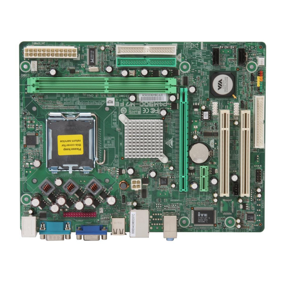
Page 6: Motherboard Layout
Motherboard Manual OT HERBOARD AYOUT JCFAN1 JKBMS1 LGA775 CPU1 JATXPWR1 JPRNT1 JUSB1 JUSBV1 JATXPWR2 P4M900 JUSBLAN1 JAUDIO1 PCI-EX16 BA T1 Super PCI-EX1_1 BIO S JSATA2 JU SB2 PCI1 VT8237A JSATA1 JCDIN1 JUSB3 PCI2 JUSBV2 JCMO S1 Codec JAUDIOF1 FDD1 JSFAN1 JPAN EL 1 Not e: represe nts the 1... -
Page 7: Chapter 2: Hardware Installation
P4M900-M7 FE CHAPTER 2: HARDWARE INSTALLATION (CPU) NST ALLING ENT RAL ROCESSING Special Notice: Remove Pin Cap before installation, and make good preservation for future use. When the CPU is removed, cover the Pin Cap on the empty socket to ensure pin legs won’t be damaged. - Page 8 Motherboard Manual Step 2: Look for the triangular cut edge on socket, and the golden dot on CPU should point forwards this triangular cut edge. The CPU will fit only in the correct orientation. Step 2-1: Step 2-2: Step 3: Hold the CPU down firmly, and then lower the lever to locked position to complete the installation.
-
Page 9: Fan Headers
P4M900-M7 FE EADERS These fan headers support cooling-fans built in the computer. The fan cable and connector may be different according to the fan manufacturer. Connect the fan cable to the connector while matching the black wire to pin#1. JCFAN1: CPU Fan Heade r... -
Page 10: Installing System Memory
Motherboard Manual NST ALLING YST EM EMORY A. Memory Modules Unlock a DIMM slot by pressing the retaining clips outward. Align a DIMM on the slot such that the notch on the DIMM matches the break on the Slot. - Page 11 P4M900-M7 FE Insert the DIMM vertically and firmly into the slot until the retaining chip snap back in place and the DIMM is properly seated. B. Memory Capacity DIMM Socket Total Memory DDR Module Location Size DIMM1 256MB/512MB/1GB/2GB Max is 4GB.
-
Page 12: Connectors And Slots
Motherboard Manual ONNECT ORS AND LOT S FDD1: Floppy Disk Conne ctor The motherboard prov ides a standard floppy disk connector that supports 360K, 720K, 1.2M, 1.44M and 2.88M floppy disk ty pes. This connector supports the prov ided f loppy drive ribbon cable. IDE1/IDE2: Hard Disk Conne ctors The motherboard has a 32-bit Enhanced PCI IDE Controller that prov ides PIO Mode 0~4, Bus Master, and Ultra DMA 33/66/100/133 f unctionality. - Page 13 P4M900-M7 FE PCI-EX16: PCI-Express x16 Slot PCI-Express 1.0a compliant. Maximum theoretical realized bandwidth of 4GB/s simultaneously per direction, f or an aggregate of 8GB/s totally. PCI-EX1_1: PCI-Express x1 Slot PCI-Express 1.0a compliant. Data transf er bandwidth up to 250MB/s per direction; 500MB/s in total.
-
Page 14: Chapter 3: Headers & Jumpers Setup
Motherboard Manual CHAPTER 3: HEADERS & JUMPERS SETUP OW T O ET UP UMPERS The illustration shows how to set up jumpers. When the jumper cap is placed on pins, the jumper is “close”, if not, that means the jumper is “open”. - Page 15 P4M900-M7 FE ATX Powe r Source Conne ctor: JATXPWR1 JATXPWR1 allows user to connect 24-pin power connector on the ATX power supply. Assignment Assignment +3.3V +3.3V -12V +3.3V Ground Ground PS_ON Ground Ground Ground Ground Ground PW_OK Standby Voltage+5V +12V...
-
Page 16: Serial Ata Connectors
Motherboard Manual JUSB2/JUSB3: Heade rs for USB 2.0 Ports at Front Panel This header allows user to connect additional USB cable on the PC f ront panel, and also can be connected with internal USB devices, like USB card reader. Assignment +5V (fused) +5V (fused) -
Page 17: Clear Cmos Header/Procedures
P4M900-M7 FE JCDIN1: CD-RO M Audio-in Connector This connector allows user to connect the audio source f rom the v ariaty dev ices, like CD-ROM, DVD-ROM, PCI sound card, PCI TV turner card etc. Assignment Left Channel Input Ground Ground... - Page 18 Motherboard Manual JPRNT1: Printe r Port Connector This header allows you to connector printer on the PC. Assignment Assignment -Strobe Ground -ALF Data 6 Data 0 Ground -Error Data 7 Data 1 Ground -Init -ACK Data 2 Ground -Scltin Busy Data 3 Ground Ground...
-
Page 19: Power Source Headers For Usb Ports
P4M900-M7 FE JUSBV1/JUSBV2: Powe r Source Heade rs for USB Ports Pin 1-2 Close: JUSBV1: +5V for USB ports at JUSB1/JUSBLAN1. JUSBV2: +5V for USB ports at f ront panel (JUSB2/JUSB3). Pin 2-3 Close: JUSBV1: USB ports at JUSB1/JUSBLAN1 are powered by +5V standby v oltage. -
Page 20: Chapter 4: Raid Functions
Motherboard Manual CHAPTER 4: RAID FUNCTIONS PERAT ION YST EM Supports Windows XP Home/Prof essional Edition, and Windows 2000 Prof essional. RRAYS RAID supports the following types of RAID arrays: RAID 0: RAID 0 defines a disk striping scheme that improves disk read and write times for many applications. - Page 21 P4M900-M7 FE RAID 1: Every read and write is actually carried out in parallel across 2 disk drives in a RAID 1 array system. The mirrored (backup) copy of the data can reside on the same disk or on a second redundant drive in the array.
-
Page 22: Chapter 5: Useful Help
Motherboard Manual CHAPTER 5: USEFUL HELP RIVER NST ALLAT ION OT E After you installed your operating system, please insert the Fully Setup Driver CD into your optical drive and install the driver for better system performance. You will see the following window after you insert the CD The setup guide will auto detect your motherboard and operating system. -
Page 23: Award Bios Beep Code
P4M900-M7 FE BIOS B WARD Beep Sound Meaning One long beep followed by two short Video card not found or v ideo card beeps memory bad High-low siren sound CPU overheated System will shut down automatically One Short beep when system boot-up No error found during POST... -
Page 24: Troubleshooting
Motherboard Manual ROUBLESHOOT ING Probable Solution No power to the system at all Make sure power cable is Power light don’t illuminate, f an securely plugged in. inside power supply does not turn Replace cable. Contact technical support. Indicator light on key board does not turn on. - Page 25 P4M900-M7 FE This page is intentionally left blank.
-
Page 26: Appendencies: Spec In Other Language
Motherboard Manual APPENDENCIES: SPEC IN OTHER LANGUAGE ERMAN Spezifikationen LGA 775 Intel Core2Duo/ Pe ntium 4 / Pentium Unterstützt Hyper -Threadi ng / Execute Disable Bit D / C eleron D / Celer on 4xx / Enha nced I ntel Spee dStep® / Intel Prozessoren mit bis zu 3,8 GHz Architecture-64 / Exte nde d Memory 64 *It is recommende d to use processors... - Page 27 190 mm (B) X 244 mm (L) öße. Sonderfun Unterstützt RAID 0 / 1 ktionen Biostar behält sich das Recht v or, ohne OS-Unters Windows 2K / XP / VISTA Ankündigung die Unterstützung für ei n tützung Betriebssystem hinzuzufügen oder zu entferne n.
-
Page 28: France
Motherboard Manual RANCE SPEC LGA 775 Prend en charge les technologies Processeurs Intel Core2Duo / P entium 4 / Hyper -Thre ading / d'ex écution de bit de Pentium D / Celeron D / Celer on 4xx désactivation / I ntel Spe edStep® optimisée/ jusqu'à... - Page 29 Fonctionna lités Prise en c harge RAID 0 / 1 spéciales Biostar se réserve le droit d'ajo uter o u de Support Windows 2K / XP / VISTA supprimer le support de SE avec o u sa ns préavis.
-
Page 30: Italian
Motherboard Manual T ALIAN SPECIFICA LGA 775 Processore Intel Core 2Duo/ Pentium 4 / Supporto di Hyper -Threadi ng / Ex ecute Disable Pentium D / Celer on D / Celeron 4xx fino Bit / Enhance d I ntel Spee dStep® / a 3.8 GHz Architettura Intel 64 / Tecnologi a Extende d *It is recommende d to use processors... - Page 31 190 mm (lar ghezza) x 244 mm (altezza) i scheda Caratterist iche Supporto RAID 0 / 1 speciali Sistemi Biostar si riserva il diritto di aggiungere o operativi Windows 2K / XP / VISTA rimuovere il supporto di qualsiasi sistema supportati operativo se nza pre avviso.
-
Page 32: Especificación
Motherboard Manual PANISH Especificación LGA 775 Procesador I ntel Core 2Duo / Penti um Admite Hyper -Threadi ng / Bit de deshabilitación 4 / Pentium D / Celero n D / Celero n de ejecució n / Intel SpeedStep® Me jorado / Intel 4xx hasta 3,8 GHz Architecture-64 / Tecnologí... - Page 33 Funciones Admite RAID 0 / 1 especiales Soporte de Biostar se reserva el derecho de aña dir o r etirar el sistema Windows 2K / XP / VISTA soporte de cualquier SO con o sin aviso previo. operativo...
-
Page 34: Portuguese
Motherboard Manual ORT UGUESE ESPECIFICAÇÕES LGA 775 Processador Intel Core2Duo / Pe ntium 4 Suporta as tecnologias Hyper -Threa ding / / Pentium D / Celer on D / Celero n 4xx Execute Disable Bit / Enha nced I ntel até... - Page 35 Característ icas Suporta as funções RAID 0 / 1 especiais Sistemas A Biostar reserva-se o direito de adicionar ou operativos Windows 2K / XP / VISTA remover suporte par a qualquer sistema suportado operativo com ou sem aviso prévio.
-
Page 36: Polish
Motherboard Manual OLISH SPEC LGA 775 Procesor Intel Cor e2Duo/ Penti um 4 / Obsługa Hyper -Threa ding / Execute Disa ble Bit Pentium D / Celeron D / Celer on 4xx do / Enha nced I ntel Spee dStep® / Intel Procesor 3,8 GHz Architecture-64 / Exte nde d Memory 64... - Page 37 Wymiary 190 mm (S) X 244 mm (W) płyty Funkcje Obsługa RAID 0 / 1 specjalne Obsluga Biostar zastrzega sobie prawo do dawania lub systemu Windows 2K / XP / VISTA odwoływania obsługi dowolnego systemu operacyjn operacyjnego bez powiadomie nia.
-
Page 38: Russian
Motherboard Manual USSIAN СПЕЦ LGA 775 Процессор Intel Core 2Duo/ Pe ntium Подде ржка техноло гий Hy per-Thre ading / (центра льны 4 / Pentium D / Celero n D / Celero n Execute Disable Bit / Enha nced I ntel й... - Page 39 технические Подде ржка RAID 0 / 1 харак терист ики Biostar сохраня ет за собо й прав о добав лять Подде ржка Windows 2K / XP / VISTA или уда лять сре дства обес пече ния для OS с или без пре дварительного уведомле ния.
-
Page 40: Arabic
Motherboard Manual RABIC اﻟﻤﻮاﺻﻔﺎت LGA 775 ﻡﻌﺎﻟﺠﺎتIntel Core2Duo/ Pe ntium 4 / Pentium ﺕﺪﻋﻢ ﺕﻘﻨﻴﺎتHyper -Thre ading / Exec ute Disabl e D / C eleron D / Celer on 4xx ﺼﻞ إﻟﻰ ﻳ ﺘﺮدد ﺑ اﻟﻤﻌﺎﻟﺠﺔ وﺣﺪة Bit / Enhance d I ntel Spee dStep® / ﺝﻴﺠﺎ... -
Page 41: Pci Express X16
P4M900-M7 FE اﻟﻤﻮاﺻﻔﺎت ﻋﺪد ﻓﺘﺤﺔ ﻋﺪد PCI Express ﻓﺘﺤﺔ اﻟﻔﺘﺤﺎت ﻋﺪد PCI Express x 1 ﻓﺘﺤﺔ ﻋﺪد ﻡﻨﻔﺬ ﻡﺤﺮك أﻗﺮاص ﻡﺮﻥﺔ ﻳﺪﻋﻢ ﻡﺤﺮآﻴﻦ ﻟﻸﻗﺮاص اﻟﻤﺮﻥﺔ ﻋﺪد ﻡﻨﻔﺬ ﻃﺎﺑﻌﺔ ﻋﺪد ﻡﻨﻔﺬ ﻳﺪﻋﻢ آﻞ ﻡﻨﻔﺬ اﺙﻨﻴﻦ ﻡﻦ أﺝﻬﺰةIDE ﻋﺪد SATA ﻡﻨﻔﺬ... -
Page 42: Japanese
Motherboard Manual APANESE 仕様 LGA 775 Intel Core2Duo/ Pe ntium 4 / Pentium Hyper -Thre ading / Exec ute Disabl e Bit / D / Celero n D / C eleron 4xx processor Enha nced Intel SpeedStep® / I ntel up to 3.8 GHz Architecture-64 / Exte nde d Memory 64 *It is recommende d to use processors... - Page 43 P4M900-M7 FE 仕様 IDEコネクタ 各コネクタは2つのIDEデバイスをサポートします SATAコネクタ 各コネクタは1つのSATAデバイスをサポートします フロントパネルコネクタ フロントパネル機能をサポートします フロントオーディオコネクタ フロントパネルオーディオ機能をサポートします CDインコネクタ CDオーディオイン機能をサポートします CPUファンヘッダ CPUファン電源装置(スマートファン機能を搭載) システムファンヘッダ システムファン電源装置 CMOSクリアヘッダ 各コネクタは2つのフロントパネルUSBポートをサポ USBコネクタ ートします 電源コネクタ(24ピン) 電源コネクタ(4ピン) PS/2キーボード PS/2マウス シリアルポート 背面パネル VGAポート LANポート USBポート オーディオジャック ボードサイ 190 mm (幅) X 244 mm (高さ) ズ...