Table of Contents
Advertisement
Quick Links
Advertisement
Table of Contents

Related Manuals for Asus CROSSHAIR V FORMULA


Summary of Contents for Asus CROSSHAIR V FORMULA
- Page 1 Crosshair V Formula Series...
- Page 2 Product warranty or service will not be extended if: (1) the product is repaired, modified or altered, unless such repair, modification of alteration is authorized in writing by ASUS; or (2) the serial number of the product is defaced or missing.
-
Page 3: Table Of Contents
Wireless Operation Channel for Different Domains ......ix France Restricted Wireless Frequency Bands ........ix IC Radiation Exposure Statement for Canada ........x Safety.information..................xi About.this.guide..................xiii Crosshair V Formula specifications summary........xv ROG ThunderBolt specifications summary.......... xviii Chapter.1:. Product.introduction 1.1. Welcome!..................1-1 1.2. - Page 4 Contents 2.3.2 CPU installation ............2-34 2.3.3 CPU heatsink and fan assembly installation ....2-35 2.3.4 DIMM installation ............2-38 2.3.5 Motherboard installation ..........2-39 2.3.6 ATX Power connection ..........2-41 2.3.7 SATA device connection ..........2-42 2.3.8 Front I/O Connector ............2-43 2.3.9 Expension Card installation ..........
- Page 5 LED Control ..............3-27 3.6. Monitor.menu................3-29 3.7. Boot.menu................... 3-33 3.8. Tools.menu.................. 3-35 3.8.1 ASUS EZ Flash 2 Utility ..........3-35 3.8.2 ASUS SPD Information ..........3-35 3.8.3 ASUS O.C. Profile ............3-36 3.8.4 GO Button File .............. 3-37 3.9.
- Page 6 Contents 4.3.10 ThunderBolt Audio ............4-31 4.3.11 Sound Blaster X-Fi MB 2 ..........4-35 RAID configurations..............4-38 4.4.1 RAID definitions ............4-38 4.4.2 Installing Serial ATA hard disks ........4-39 4.4.3 Setting the RAID item in BIOS ........4-39 4.4.4 Option ROM Utility ..........
-
Page 7: Notices
Notices Federal.Communications.Commission.Statement This device complies with Part 15 of the FCC Rules. Operation is subject to the following two conditions: • This device may not cause harmful interference, and • This device must accept any interference received including interference that may cause undesired operation. -
Page 8: Declaration Of Conformity (R&Tte Directive 1999/5/Ec)
RF.exposure.warning This equipment must be installed and operated in accordance with provided instructions and the antenna(s) used for this transmitter must be installed to provide a separation distance of at least 20 cm from all persons and must not be co-located or operating in conjunction with any other antenna or transmitter. End-users and installers must be provide with antenna installation instructions and transmitter operating conditions for satisfying RF exposure compliance. -
Page 9: Wireless Operation Channel For Different Domains
Wireless.Operation.Channel.for.Different.Domains N. America 2.412-2.462 GHz Ch01 through CH11 Japan 2.412-2.484 GHz Ch01 through Ch14 Europe ETSI 2.412-2.472 GHz Ch01 through Ch13 France.Restricted.Wireless.Frequency.Bands Some areas of France have a restricted frequency band. The worst case maximum authorized power indoors are: • 10mW for the entire 2.4 GHz band (2400 MHz–2483.5 MHz) •... -
Page 10: Ic Radiation Exposure Statement For Canada
Canadian.Department.of.Communications.Statement This digital apparatus does not exceed the Class B limits for radio noise emissions from digital apparatus set out in the Radio Interference Regulations of the Canadian Department of Communications. This class B digital apparatus complies with Canadian ICES-003. Cet appareil numérique de la classe [B] est conforme à... -
Page 11: Safety.information
Safety information Electrical.safety • To prevent electrical shock hazard, disconnect the power cable from the electrical outlet before relocating the system. • When adding or removing devices to or from the system, ensure that the power cables for the devices are unplugged before the signal cables are connected. If possible, disconnect all power cables from the existing system before you add a device. - Page 12 Operation.safety • Before installing the motherboard and adding devices on it, carefully read all the manuals that came with the package. • Before using the product, ensure all cables are correctly connected and the power cables are not damaged. If you detect any damage, contact your dealer immediately.
-
Page 13: About.this.guide
Refer to the following sources for additional information and for product and software updates. ASUS.websites The ASUS website provides updated information on ASUS hardware and software products. Refer to the ASUS contact information. Optional.documentation Your product package may include optional documentation, such as warranty flyers, that may have been added by your dealer. - Page 14 Conventions.used.in.this.guide To ensure that you perform certain tasks properly, take note of the following symbols used throughout this manual. DANGER/WARNING: Information to prevent injury to yourself when trying to complete a task. CAUTION: Information to prevent damage to the components when trying to complete a task.
-
Page 15: Crosshair V Formula Specifications Summary
4 x DIMM, max. 32GB, DDR3 2133(O.C.)/2000(O. C.)/1800(O.C.)/1600/1333/1066 MHz, ECC and non- ECC, un-buffered memory *Refer to www.asus.com or user manual for the Memory QVL (Qualified Vendors Lists) **Due to OS limitation, when installing total memory of 4GB capacity or more, Windows... - Page 16 - ASUS C.P.R.(CPU Parameter Recall) Other.Special.Features Core Unlocker ASUS Fan Xpert ASUS Q-Connector ASUS Q-Shield ASUS Q- LED (CPU, DRAM, VGA, Boot Device LEDs) Ai Charger+ ASUS EZ Flash 2 ASUS MyLogo 3 BIOS.Features 32Mb Flash ROM, UEFI BIOS, PnP, DMI2.0, WfM2.0, SM BIOS 2.5, ACPI2.0a Multi-Language BIOS...
- Page 17 Crosshair V Formula specifications summary Internal.I/O.Connectors 1 x USB 3.0/2.0 connector supports additional 2 USB 3.0/2.0 ports 2 x USB 2.0/1.1 connectors support additional 4 USB 2.0/1.1 ports 7 x SATA 6Gb/s connectors (Red) 8 x Fan connectors: 2 x CPU / 3 x Chassis / 3x Optional...
-
Page 18: Rog Thunderbolt Specifications Summary
ROG ThunderBolt specifications summary ThunderBolt.LAN/ Dedicated.Network.Processing.Unit.(NPU) Audio.Combo.Card - Advanced Game Detect™ - Visual Bandwidth Control™ - Application Blocking - Online Gaming PC Monitor™ - Bandwidth Tester - Game Networking DNA™ Built-in.2-Channel.High.Quality.DAC/ADC - Output Signal-to-Noise Ratio (A-Weighted): 116dB - Output THD+N at 1KHz: 105dB - C-Media 6631 audio processor (Max. -
Page 19: Chapter 1: Product Introduction
This chapter describes the motherboard features and the new technologies it supports. Chapter 1: Product introduction... - Page 20 Chapter summary 1.1. Welcome!..................1-1 1.2. Package.contents................1-1 1.3. Special.features................1-2 ROG Crosshair V Formula...
-
Page 21: Welcome
Welcome! Thank you for buying an ROG Crosshair V Formula motherboard! The motherboard delivers a host of new features and latest technologies, making it another standout in the long line of ASUS quality motherboards! Before you start installing the motherboard, and hardware devices on it, check the items in your package with the list below. -
Page 22: Special.features
This motherboard supports DDR3 2133(O.C.) that provides faster data transfer rate and more bandwith to increase memory computing efficiency, enhancing system performance in 3D graphics and other memory demanding applications. Refer to www.asus.com for the supported CPU models. Chapter 1: Product Introduction... -
Page 23: Rog Thunderbolt Lan/Audio Combo
SLI/CrossFireX.On-Demand.. Why.choose.when.you.can.have.both? SLI or CrossFireX? Fret no longer because with the ROG Crosshair V Formula, you'll be able to run both multi-GPU setups. The board features SLI/CrossFireX on Demand technology, supporting SLI or CrossFireX configuration. Whichever path you take, you can be assured of jaw-dropping graphics at a level previously unseen. -
Page 24: Rog Intelligent Performance & Overclocking Features
1.3.3. ROG.Intelligent.Performance.&.Overclocking.features Extreme.Engine.Digi+. Powerful.combination.of.analog.and.digital.design.elements Extreme Engine Digi+ equipped with high performance digital VRM design can easily achieve the ultimate performance with adjustable CPU PWM frequency. It expedites heat dissipation and achieves better electric conduction keeping critical components reliable. Now you'll be able to push your spanking new CPU to the limit, hitting benchmark scores that others only dream of. - Page 25 ROG offers a whole new UEFI BIOS feature to handle the demands of an overclocking experience. Crosshair V Formula features ROG BIOS Print which allows users to easily share their BIOS settings to others with the press of a button.
- Page 26 Extreme.Tweaker.. One.stop.performance.tuning.shop Extreme Tweakers is the one stop shop to fine-tune your system to optimal performance. No matter if you're looking for frequency adjustment, over-voltage options, or memory timing settings, they're all here! Voltiminder.LED.. Friendly.reminder.on.Voltage.Settings In the pursuit of extreme performance, overvoltage adjustment is critical but risky.
-
Page 27: Asus Special Features
ASUS.TPU.. The.Ultimate.O.C..Processor Unleash your performance with ASUS’ simple onboard switch or AI Suite II utility. The TPU chip offers precise voltage control and advanced monitoring through Auto Tuning and TurboV functions. Auto Tuning offers a user friendly way to automtically... - Page 28 ASUS.Fan.Xpert ASUS Fan Xpert intelligently allows you to adjust both the CPU and chassis fan speeds according to different ambient temperatures caused by different climate conditions in different geographic regions and your PC’s loading. The built-in variety of useful profiles offer flexible controls of fan speed to achieve a quiet and cool environment.
-
Page 29: Chapter 2: Hardware Information
This chapter lists the hardware setup procedures that you have to perform when installing system components. It includes description of the jumpers and Chapter 2: Hardware connectors on the motherboard. information... - Page 30 Chapter summary 2.1. Before.you.proceed..............2-1 2.2. Motherboard.overview..............2-2 2.3. Building.your.computer.system..........2-32 Starting up for the first time............2-50 2.5. Turning.off.the.computer............2-51 ROG Crosshair V Formula...
-
Page 31: Before.you.proceed
Before you install or remove any component, ensure that the ATX power supply is switched off or the power cord is detached from the power supply. Failure to do so may cause severe damage to the motherboard, peripherals, or components. ROG Crosshair V Formula... -
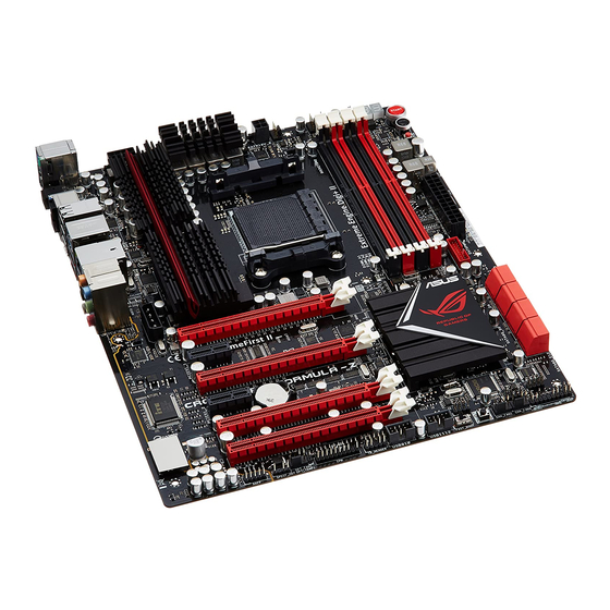
Page 32: Motherboard.overview
Motherboard overview 2.2.1. Motherboard.layout Chapter 2: Hardware information... -
Page 33: Layout Contents
2-30 Front panel audio connector (10-1 pin AAFP) 2-24 Digital audio connector (4-1 pin SPDIF_OUT) 2-23 ROG connect switch (3-pin ROG) 2-29 Refer to 2.2.8 and 2.3.11 for more information about internal and rear panel connectors. ROG Crosshair V Formula... -
Page 34: Central Processing Unit (Cpu)
2.2.3. Central.Processing.Unit.(CPU) The motherboard comes with an AM3+ socket designed for AMD® Next Generation CPU up to 8-core, also compatible with AMD® socket AM3 for AMD® Phenom™ II/Athlon™ II/ Sempron™ 100 Series Processors. Ensure that all power cables are unplugged before installing the CPU. Ensure that you use a CPU designed for the AM3+/AM3 socket. -
Page 35: System Memory
The motherboard comes with four Double Data Rate 3 (DDR3) Dual Inline Memory Modules (DIMM) slots. A DDR3 module is notched differently from a DDR or DDR2 module. DO NOT install a DDR or DDR2 memory module to the DDR3 slot. ROG Crosshair V Formula... -
Page 36: Memory Configurations
Memory configurations You may install 512MB, 1GB, 2GB, 4GB, and 8GB unbuffered ECC and non-ECC DDR3 DIMMs into the DIMM sockets. • You may install varying memory sizes in Channel A and Channel B. The system maps the total size of the lower-sized channel for the dual-channel configuration. - Page 37 Crosshair V Formula Motherboard Qualified Vendors Lists (QVL). DDR3.1066.MHz.capability DIMM.socket. support.(Optional) Vendors Part.No. Size Chip.Brand Chip.NO. Timing Voltage 2.DIMM 4.DIMM Crucial CT12864BA1067.8FF MICRON D9KPT • • Crucial CT12864BA1067.8SFD MICRON D9JNL • • Crucial CT12872BA1067.9FF MICRON D9KPT(ECC) • • Crucial CT25664BA1067.16FF...
- Page 38 (DDR3 1333 MHz continued) Hynix HMT325U6BFR8C-H9 Hynix H5TQ2G83BFR • • Hynix HMT125U6BFR8C-H9 Hynix H5TQ1G83BFRH9C • • Hynix HMT125U6TFR8A-H9 Hynix H5TC1G83TFR • • Hynix HMT351U6BFR8C-H9 Hynix H5TQ2G83BFR • • KINGMAX FLFE85F-C8KM9 Kingmax KFC8FNMXF-BXX-15A • KINGMAX FLFE85F-B8KL9 KINGMAX KFB8FNLXL-BNF-15A • • KINGMAX FLFF65F-C8KM9 Kingmax KFC8FNMXF-BXX-15A...
- Page 39 Crosshair V Formula Motherboard Qualified Vendors Lists (QVL). DDR3.1600.MHz.capability DIMM.socket. Chip. support.(Optional) Vendors Part.No. Size Chip.NO. Timing Voltage Brand 2.DIMM 4.DIMM A-DATA AX3U1600GC4G9(XMP) 9-9-9-24 1.55~1.75 • • A-DATA AX3U1600XC4G79(XMP) 7-9-7-21 1.55~1.75 • • CORSAIR HX3X12G1600C9(XMP) 12GB (6 x 2GB ) 9-9-9-24 •...
- Page 40 Team TXD32048M1600C7-L(XMP) Team 7-7-7-24 1.65 • • T3D1288RT- Team TXD32048M1600HC8-D(XMP) Team 8-8-8-24 1.65 • • Crosshair V Formula Motherboard Qualified Vendors Lists (QVL). DDR3.1800.MHz.capability DIMM.socket.support. Chip. (Optional) Vendors Part.No. Size Chip.NO. Timing Voltage Brand 1.DIMM 2.DIMM 4.DIMM G.SKILL F3-14400CL6D-4GBFLS(XMP) 4GB (2 x 2GB) DS - 6-8-6-24 1.65...
-
Page 41: Memory Configuration
9-11-9-27 1.65 • • Team TXD32048M2000C9(XMP) DS Team T3D1288RT-20 9-9-9-24 • Team TXD32048M2000C9-L(XMP) DS Team T3D1288RT-20 9-9-9-24 • Crosshair V Formula Motherboard Qualified Vendors Lists (QVL). DDR3.2133.MHz.capability DIMM.socket.support. (Optional) Vendors Part.No. Size SS/DS Chip.Brand Chip.NO. Timing Voltage 2.DIMM 4.DIMM G.SKILL... -
Page 42: Expansion Slots
2.2.5. Expansion.slots In the future, you may need to install expansion cards. The following sub-sections describe the slots and the expansion cards that they support. Ensure to unplug the power cord before adding or removing expansion cards. Failure to do so may cause you physical injury and damage motherboard components. - Page 43 PCI Express specifications. Refer to the figure below for the location of the slot. PCI.Express.operating.mode VGA configuration PCIe.x16_1 PCIe.x8/x1_2 PCIe.x16/x8_3 x16 (Recommend Single.VGA/PCIe.card x16 (Single VGA) for single VGA) Dual.VGA/PCIe.card Triple.VGA/PCIe.card ROG Crosshair V Formula 2-13...
- Page 44 • In single VGA card mode, use first the PCIe 2.0 x16_1 slot or PCIe 2.0 x16/ x8_3 slot for a PCI Express x16 graphics card to get better performance. • In CrossFireX™ or SLI™ mode, use the PCIe 2.0 x16_1 and PCIe 2.0 x16/ x8_3 slots for PCI Express x16 graphics cards to get better performance.
-
Page 45: Onboard Leds
VDDPCIE The southbridge LED shows either the SB voltage or the HT voltage. You can select the voltage to display in BIOS. Refer to the illustration below for the location of the northbridge/southbridge LEDs and the table below for LED definition. ROG Crosshair V Formula 2-15... - Page 46 Normal.(green) High.(yellow) Crazy.(red) CPU.Voltage.(default) by CPU–1.36875 1.3750–1.49375 1.5–by CPU CPU/NB.Voltage by CPU–1.36875 1.3750–1.49375 1.5–by CPU VDDA.Voltage.2.5V 2.20000–2.76875 2.77500–3.00625 3.01250–3.18750 NB.Voltage 0.80000–1.59375 1.60000–1.84375 1.85000-2.00000 NB.1.8.Voltage 1.80200-1.89475 1.90800-1.94775 1.96100-3.00775 VDD.PCIE.Voltage 1.11300-1.59000 1.60325-1.84175 1.85500-2.00075 SB.Voltage 1.11300-1.44425 1.45750-1.69600 1.70925-1.802 HT.Voltage 0.80000–1.39375 1.40000-1.65000 1.65625-2.00000 DRAM.BUS.1.5V.Voltage 1.20000-1.72500 1.73125-2.32500 2.33125-2.90000...
- Page 47 If an error is found , the corresponding LED will continue lighting until the problem is solved. This user-friendly design provides an intuitional way to locate the root problem within a second. ROG Crosshair V Formula 2-17...
- Page 48 Power.LED The motherboard comes with a power-on switch that lights up to indicate that the system is ON, in sleep mode, or in soft-off mode. This is a reminder that you should shut down the system and unplug the power cable before removing or plugging in any motherboard component.
-
Page 49: Clear Rtc Ram
• Due to the chipset behavior, AC power off is required to enable C.P.R. function. You must turn off and on the power supply or unplug and plug the power cord before rebooting the system. ROG Crosshair V Formula 2-19... -
Page 50: Internal Connectors
2.2.8. Internal.connectors AMD SB950 Serial ATA connectors (7-pin SATA6G_1-6) AMD.SB950.Serial.ATA.connectors.(7-pin.SATA6G_1-6) These connectors are for the Serial ATA signal cables for Serial ATA hard disk drives and optical disc drives. If you installed Serial ATA hard disk drives, you can create a RAID 0, 1, 5, and 10 configuration with the onboard AMD SB950 RAID controllers. - Page 51 These connectors are for USB 2.0 ports. Connect the USB module cables to these connectors, then install the modules to slots opening at the back of the system chassis. This USB connectors comply with USB 2.0 specification that supports up to 480 Mbps connection speed. ROG Crosshair V Formula 2-21...
- Page 52 You can connect the USB 2.0 cable to ASUS Q-Connector (USB, blue) first, and then install the Q-Connector (USB) to the USB 2.0 connector onboard. USB.3.0.connectors.(18-1.pin.USB3_56) These connectors are for USB 3.0 ports. Connect the USB 3.0 module cables to these connectors, then install the modules to slots opening at the back of the system chassis.
- Page 53 DO NOT place jumper caps on the fan connectors! If you install two VGA cards, we recommend that you plug the chassis fan cable to the motherboard connector labeled OPT_FAN1/2/3 for better thermal environment. ROG Crosshair V Formula 2-23...
- Page 54 Thermal.sensor.cable.connectors.(2-pin.OPT_TEMP1/2/3) These connectors are for temperature monitoring. Connect the thermal sensor cables to these connectors and place the other ends to the devices which you want to monitor temperature. The optional fan1/2/3 can work with the temperature sensors for a better cooling effect. Enable OPT.FAN1/2/3.overheat.protection in BIOS if you connect thermal sensor cables to these connectors.
- Page 55 Front.Panel.Type item in the BIOS setup to [HD.Audio];. if you want to connect an AC'97 front panel audio module to this connector, set the item to [AC97]. By default, this connector is set to [HD.Audio]. ROG Crosshair V Formula 2-25...
- Page 56 Appendix for the certified 500W power supply or above. • If you are uncertain about the minimum power supply requirement for your system, refer to the Recommended Power Supply Wattage Calculator at http://support.asus.com/PowerSupplyCalculator/PSCalculator. aspx?SLanguage=en-us for details. Chapter 2: Hardware information 2-26...
- Page 57 BIOS settings. Pressing the power switch for more than four seconds while the system is ON turns the system OFF. •. Reset.button.(2-pin.RESET) This 2-pin connector is for the chassis-mounted reset button for system reboot without turning off the system power. ROG Crosshair V Formula 2-27...
-
Page 58: Asus Q-Connector
11.. ASUS.Q-Connector.(system.panel) Use the ASUS Q-Connector to connect/disconnect the chassis front panel cables. To install the ASUS Q-Connector: Connect the front panel cables to the ASUS Q-Connector. Refer to the labels on the Q-Connector to know the detailed pin definitions, and then match them to their respective front panel cable labels. -
Page 59: Onboard Switches
This is ideal for overclockers and gamers who continually change settings to enhance system performance. Power-on.switch Press the power-on switch to wake/power up the system. Reset.switch Press the reset switch to reboot the system. ROG Crosshair V Formula 2-29... - Page 60 GO.button Press the GO button before POST to enable MemOK! or press it to quickly load the preset profile (GO_Button file) for temporary overclocking when in ROG.Connect.switch Use the ROG Connect switch to enable/disable the ROG Connect fuctions. Chapter 2: Hardware information 2-30...
- Page 61 CPU.Level.Up.switch Use the CPU Level Up switch to overclock immediately with OC profile presets without the hassle of entering BIOS. ROG Crosshair V Formula 2-31...
-
Page 62: Probeit
2.2.10. ProbeIt The ROG ProbeIt feature provides a nice touch for your convenient and accurate OC settings. No time wasted fumbling around on the complicated motherboard layout, the clearly marked area gives you easier access to the measure points when a multitester is employed for more accurate measurements during your busy overclocking work. -
Page 63: Building.your.computer.system
Building your computer system 2.3.1. Additional.tools.and.components.to.build.a.PC.system 1.bag.of.screws Philips.(cross).screwdriver PC.chassis Power.supply.unit AMD.AM3+/AM3.CPU AMD.AM3+.compatible.CPU.Fan DIMM SATA.hard.disk.drive SATA.optical.disc.drive.(optional) Graphics.card The tools and components in the table above are not included in the motherboard package. ROG Crosshair V Formula 2-33... -
Page 64: Cpu Installation
2.3.2. CPU.installation The AM3+ socket has a different pinout from the AM2+/AM2 socket. Ensure you use a CPU designed for the AM3+ socket. The CPU fits in only one correct orientation. DO NOT force the CPU into the socket to prevent bending the connectors on the socket and damaging the CPU! Chapter 2: Hardware information 2-34... -
Page 65: Cpu Heatsink And Fan Assembly Installation
2.3.3. CPU.heatsink.and.fan.assembly.installation Apply the Thermal Interface Material to the CPU heatsink and CPU before you install the heatsink and fan if necessary. ROG Crosshair V Formula 2-35... - Page 66 2.3.3. To.install.the.CPU.heatsink.and.fan.assembly Chapter 2: Hardware information 2-36...
- Page 67 ROG Crosshair V Formula 2-37...
-
Page 68: Dimm Installation
2.3.4. DIMM.installation To.remove.a.DIMM Chapter 2: Hardware information 2-38... -
Page 69: Motherboard Installation
2.3.5. Motherboard.installation The diagrams in this section are for reference only. The motherboard layout may vary with models, but the installation steps remain the same. ROG Crosshair V Formula 2-39... - Page 70 DO NOT overtighten the screws! Doing so can damage the motherboard. Chapter 2: Hardware information 2-40...
-
Page 71: Atx Power Connection
2.3.6. ATX.Power.connection ROG Crosshair V Formula 2-41... -
Page 72: Sata Device Connection
2.3.7. SATA.device.connection Chapter 2: Hardware information 2-42... -
Page 73: Front I/O Connector
2.3.8. Front.I/O.Connector To.install.ASUS.Q-Connector To.install.USB.Connector To.install.front.panel.audio. connector AAFP ROG Crosshair V Formula 2-43... -
Page 74: Expension Card Installation
2.3.9. Expension.Card.installation To.install.PCIe.x16.cards To.install.PCIe.x1.cards To.install.PCI.cards Chapter 2: Hardware information 2-44... -
Page 75: Installing Thunderbolt
Locate the most suitable PCIe x1 or PCIe x16 slot for the ThunderBolt. You can either install ThunderBolt to the PCIe x1 slot or the PCIe x16 slot. Align the card connector with the slot and press firmly until the card sits on the slot completely. ROG Crosshair V Formula 2-45... - Page 76 Connect the USB cable to the onboard USB connector. Connect the 4-pin molex power connector to the ThunderBolt. • Ensure to connect the AAFP cable from the chassis front panel to the ThunderBolt AAFP connector. • Install the ThunderBolt on the PCIE x16 slot for a better LAN performance. •...
-
Page 77: Rear Panel Connectors
See section 3.5.6 Onboard Devices Configuration for details. *.LAN.port.LED.indications Activity/. Speed. Speed.LED Activity/Link Description Link.LED Soft-off Mode Yellow Blinking 10 Mbps connection or suspend Yellow Blinking ORANGE 100 Mbps connection LAN.port Yellow Blinking GREEN 1 Gbps connection ROG Crosshair V Formula 2-47... -
Page 78: Audio I/O Connections
2.3.12. Audio.I/O.connections Audio 2, 4, 6, or 8-channel configuration Headset. Port 4-channel 6-channel 8-channel 2-channel Light Blue Line In Line In Line In Line In Lime Line Out Front Speaker Out Front Speaker Out Front Speaker Out Pink Mic In Mic In Mic In Mic In... - Page 79 Connect.to.Stereo./.2.1-channel.Speakers Connect.to.4.1-channel.Speakers Connect.to.5.1-channel.Speakers ROG Crosshair V Formula 2-49...
- Page 80 Connect.to.7.1-channel.Speakers Chapter 2: Hardware information 2-50...
-
Page 81: Starting Up For The First Time
No VGA detected short beeps One continuous beep followed by four Hardware component failure short beeps At power on, hold down the <Delete> key to enter the BIOS Setup. Follow the instructions in Chapter 3. ROG Crosshair V Formula 2-51... -
Page 82: Turning.off.the.computer
Turning off the computer 2.5.1. Using.the.OS.shut.down.function If you are using Windows Vista™/ Windows ® ® Click the Start button then select Shut.Down. The power supply should turn off after Windows shuts down. ® If you are using Windows ® Click the Start button then select Turn.Off.Computer. Click the Turn.Off button to shut down the computer. -
Page 83: Bios Setup
This chapter tells how to change the system settings through the BIOS Setup menus. Detailed descriptions of the BIOS parameters are also provided. BIOS setup... - Page 84 Chapter summary 3.1. Knowing.BIOS................3-1 3.2. BIOS.setup.program..............3-1 3.3. Extreme.Tweaker.menu..............3-5 Main menu Main menu .menu................... 3-12 3.5. Advanced.menu................3-15 3.6. Monitor.menu................3-29 3.7. Boot.menu................... 3-33 3.8. Tools.menu.................. 3-35 3.9. Exit.menu..................3-38 3.10. Updating.BIOS................3-39 ROG Crosshair V Formula...
-
Page 85: Knowing.bios
USB mouse. The BIOS setup program can be used under two modes: EZ.Mode and Advanced. Mode. You can change modes from the Exit menu or from the Exit/Advanced. Mode button in the EZ.Mode/Advanced.Mode screen. ROG Crosshair V Formula... -
Page 86: Ez Mode
Exits.the.BIOS.setup.program.without.saving. temperature,.CPU/5V/3.3V/12V.voltage. the.changes,.saves.the.changes.and.resets. output,.CPU/chassis/power.fan.speed the.system,.or.enters.the.Advanced.Mode Power.Saving.mode Loads.optimized.default. Selects.the.boot.device..priority Normal.mode ASUS.Optimal. Displays.the.system.properties.of. mode the.selected.mode.on.the.right.hand. side. • The boot device options vary depending on the devices you installed to the system. The Boot.Menu(F8) button is available only when the boot device is •... -
Page 87: Advanced Mode
The Advanced Mode provides advanced options for experienced end-users to configure the BIOS settings. The figure below shows an example of the Advanced Mode. Refer to the following sections for the detailed configurations. To access the EZ Mode, click Exit, then select ASUS.EZ.Mode. Menu. Configuration General. -
Page 88: Configuration Fields
Menu.items The highlighted item on the menu bar displays the specific items for that menu. For example, selecting Main shows the Main menu items. The other items (Extreme Tweaker, Advanced, Monitor, Boot, Tool, and Exit) on the menu bar have their respective menu items. Back.button This button appears when entering a submenu. -
Page 89: Extreme.tweaker.menu
Be cautious when changing the settings of the Extreme Tweaker menu items. Incorrect field values can cause the system to malfunction. The configuration options for this section vary depending on the CPU and DIMM model you installed on the motherboard. Scroll down to display the following items: ROG Crosshair V Formula... - Page 90 Scroll down to display the following items: Ai.Overclock.Tuner.[Auto] Allows you to select the CPU overclocking options to achieve the desired CPU internal frequency. Select any of these preset overclocking configuration options: [Auto] Loads the optimal settings for the system. [Manual] Allows you to individually set overclocking parameters.
- Page 91 Configuration options: [Auto] [1x] [1.25x] [1.5x] [2x] MEMCLK drive strength [Auto] Configuration options: [Auto] [0.75x] [1x] [1.25x] [1.5x] Data drive strength [Auto] Configuration options: [Auto] [0.75x] [1x] [1.25x] [1.5x] DQS drive strength [Auto] Configuration options: [Auto] [0.75x] [1x] [1.25x] [1.5x] ROG Crosshair V Formula...
- Page 92 Processor ODT [Auto] Configuration options: [Auto] [240 ohms +/- 20%] [120 ohms +/- 20%] [60 ohms +/- 20%] DCT1.Information: CKE drive strength [Auto] Configuration options: [Auto] [1x] [1.25x] [1.5x] [2x] CS/ODT drive strength [Auto] Configuration options: [Auto] [1x] [1.25x] [1.5x] [2x] ADDR/CMD drive strength [Auto] Configuration options: [Auto] [1x] [1.25x] [1.5x] [2x] MEMCLK drive strength [Auto]...
- Page 93 Reducing phase number under light system loading to increase VRM efficiency [Standard] Proceeds phase control depending on the CPU loading. [Optimized] Loads the ASUS optimized phase tuning profile. [Extreme] Proceeds the full phase mode. [Manual Adjustment] Allows manual adjustment VRM.Over.Temperature.Protection.[Enabled] CPU.Voltage.Frequency.[Auto]...
- Page 94 Extreme.OV.[Disabled] [Enabled] Enables the Extreme OV function. [Disabled] Disables this function. CPU.&.CPU/NB.Voltage.mode.[Manual.Mode] [Manual Mode] Allows you to set a fixed CPU voltage. [Offset Mode] Allows you to set the Offset voltage. CPU Manual Voltage [Auto] This item appears only when you set the CPU & NB Voltage item to [Manual Mode] and allows you to set a fixed CPU voltage.
- Page 95 Allows you to switch NB voltage frequency. Configuration options: [Auto] [1] [2x] NB.1.8V.Switching.Frequency.[Auto] Allows you to switch NB 1.8V voltage frequency. Configuration options: [Auto] [1] [2x] VDD.PCIE.Switching.Frequency.[Auto] Allows you to switch VDD PCIE voltage frequency. Configuration options: [Auto] [1] [2x] ROG Crosshair V Formula 3-11...
-
Page 96: Main.menu
Main menu The Main menu screen appears when you enter the Advanced Mode of the BIOS Setup program. The Main menu provides you an overview of the basic system information, and allows you to set the system date, time, language, and security settings. -
Page 97: Security
BIOS setup program. To set an administrator password: Select the Administrator.Password item and press <Enter>. From the Create.New.Password box, key in a password, then press <Enter>. Confirm the password when prompted. ROG Crosshair V Formula 3-13... - Page 98 To change an administrator password: Select the Administrator.Password item and press <Enter>. From the Enter.Current.Password box, key in the current password, then press <Enter>. From the Create.New.Password box, key in a new password, then press <Enter>. Confirm the password when prompted. To clear the administrator password, follow the same steps as in changing an administrator password, but press <Enter>...
-
Page 99: Advanced.menu
The Advanced menu items allow you to change the settings for the CPU and other system devices. Be cautious when changing the settings of the Advanced menu items. Incorrect field values can cause the system to malfunction. ROG Crosshair V Formula 3-15... -
Page 100: Cpu Configuration
3.5.1 CPU Configuration The items in this menu show the CPU-related information that the BIOS automatically detects. The items shown in this screen may be different due to the CPU you installed. Cool‘n’Quiet.[Disabled] [Enabled] Enables the AMD Cool’n’Quiet function. [Disabled] Disables this function. -
Page 101: North Bridge Configuration
Allows you to select unganged DRAM mode (64-bit width). [Enabled]: Unganged mode. [Disabled]: Ganged mode. Initiate.Graphic.Adapter.[PEG/PCI] Allows you to decide which graphics controller to use as the primary boot device. Configuration options: [PCI/PEG] [PEG/PCI] Socket.0.Information View information related to Socket 0. ROG Crosshair V Formula 3-17... -
Page 102: Sata Configuration
3.5.3 SATA Configuration While entering Setup, the BIOS automatically detects the presence of SATA devices. The SATA Port items show Not.Present if no SATA device is installed to the corresponding SATA port. Onchip.SATA.Channel.[Enabled] Configuration options: [Disabled] [Disabled] SATA.Port1-Port4.[AHCI] Allows you to set the SATA configuration. This item appears only when you set the OnChip SATA Channel item to [Enabled]. - Page 103 When read/write of your hard disk errors occur, this feature allows the hard disk to report warning messages during the POST. Configuration options: [Disabled] [Enabled] SATA.Hot.Plug.on.PORT1-6.[Disabled] Allows you to set SATA Hot Plug on PORT1-6 to external SATA port. Configuration options: [Disabled] [Enabled] ROG Crosshair V Formula 3-19...
-
Page 104: Usb Configuration
3.5.4 USB Configuration The items in this menu allow you to change the USB-related features. The USB Devices item shows the auto-detected values. If no USB device is detected, the item shows None. Legacy.USB.Support.[Enabled] [Disabled] Disables the function. [Enabled] Enables the support for USB devices on legacy operating systems (OS). -
Page 105: Sb Usb Configuration
USB PORT FL0-FL1 [Enabled] Enable or disable USB port FL0-FL1. Configuration options: [Disabled] [Enabled] USB Device Wakeup From S3 or S4 [Enabled] Enable or disable USB Device Wakeup From S3 or S4 funtion. Configuration options: [Disabled] [Enabled] ROG Crosshair V Formula 3-21... -
Page 106: Cpu Core On/ Off Function
3.5.5. CPU.Core.On/.Off.Function ASUS.Core.Unlocker.[Disabled] Allows you to enable ASUS Core Unlocker to get full computing power of processor.Configuration options: [Disabled] [Enabled] System might become unstable due to different CPU margins. CPU.Core.Activation.[Auto] Allows you to manually turn off the second or the third core. -
Page 107: Onboard Devices Configuration
This item appears only when you set the previous item to [Enabled] and allows you to enable or disable the OptionRom of the ASM1061 storage controller. Configuration options: [Enabled] [Disabled] Asmedia.USB.3.0.Controller.[Enabled] [Enabled] Enables the Asmedia USB 3.0 Controller. [Disabled] Disables the controller. ROG Crosshair V Formula 3-23... - Page 108 Asmedia.USB.3.0.Battery.Charging.Support.[Disabled] [Enabled] Enables the Asmedia USB 3.0 Battery Charging Support fuction. [Disabled] Disables the fuction. Intel.82583.LAN.[Enabled] [Enabled] Enables the Intel 82583 LAN controller. [Disabled] Disables the controller. Launch.PXE.OPROM.[Disabled] This item appears only when you set the previous item to [Enabled] and allows you to enable or disable boot option for PXE OPROM.
-
Page 109: Apm
Enables the PME devices to generate a wake event. Power.On.By.RTC.[Disabled] [Disabled] Disables RTC to generate a wake event. [Enabled] When set to [Enabled], the items RTC Alarm Date (Days) and Hour/Minute/Second will become user-configurable with set values. ROG Crosshair V Formula 3-25... -
Page 110: Irog Configuration
3.5.8 iROG Configuration iROG.Timer.Keeper.[Last.State] Allows you to set the iROG Time Keeper operation mode. Configuration options: [Last State] [Disabled] [Enabled] 3.5.9. ROG.Connect ROG.Connect.[Enabled] Allows you to enable or disable the ROG Connect function. Configuration options: [Enabled] [Disabled] RC.Poster.Mode.[String] RC Poster describes what occurs during the POST. Configuration options: [String] [Code] 3-26 Chapter 3: BIOS setup... -
Page 111: Led Control
Allows you to enable or disable the onboard Voltiminder LED. Configuration options: [Enabled] [Disabled] CPU.LED.Selection.[CPU] Allows you to switch the onboard CPU LED display between CPU voltage [CPU], CPU/NB voltage [CPU/NB], and CPU VDDA [CPU VDDA]. Configuration options: [CPU] [CPU/NB] [CPU VDDA] ROG Crosshair V Formula 3-27... - Page 112 NB.LED.Selection.[NB] Allows you to switch the onboard NB LED display between NB voltage [NB], NB 1.8V [NB 1.8V], and VDDPCIE voltage [VDDPCIE]. Configuration options: [NB] [NB 1.8V] [VDDPCIE] SB.LED.Selection.[SB] Allows you to switch the onboard SB LED display between SB voltage [NB] and HT voltage [HT].
-
Page 113: Monitor.menu
NB Overheat Protection [90ºC] The system automatically shuts down when the NB is heated over the set temperature to protect it from damage. Configuration options: [Disabled] [70ºC] [80ºC] [90ºC] [100ºC] ROG Crosshair V Formula 3-29... - Page 114 SB Overheat Protection [90ºC] The system automatically shuts down when the SB is heated over the set temperature to protect it from damage. Configuration options: [Disabled] [70ºC] [80ºC] [90ºC] [100ºC] OPT TEMP1/2/3 Overheat Protection [90ºC] Allows you to set the temperature over which the system automatically shuts down when any of the thermal sensor cables connected to the motherboard detects device overheat to protect the device from damage.
- Page 115 Use the <+> and <-> keys to adjust the maximum chassis fan duty cycle. The values range from 60% to 100%. When the chassis temperature reaches upper limit, the chassis fan will operate at the maximum duty cycle. ROG Crosshair V Formula 3-31...
- Page 116 Chassis.Fan.Min..Duty.Cycle(%).[60] Use the <+> and <-> keys to adjust the minimum chassis fan duty cycle. The values range from 60% to 100%. When the chassis temperature is under 40ºC, the chassis fan will operate at the minimum duty cycle. Chassis.Fan.Speed.Low.Limit.[600.RPM] This item appears only when you enable the Chassis Q-Fan Control feature and allows you to disable or set the chassis fan warning speed.
-
Page 117: Boot.menu
Boot menu The Boot menu items allow you to change the system boot options. ROG Crosshair V Formula 3-33... - Page 118 Enables the full screen logo display feature. [Disabled] Disables the full screen logo display feature. Set this item to [Enabled] to use the ASUS MyLogo 3™ feature. Option.ROM.Messages.[Force.BIOS] [Force BIOS] The third-party ROM messages will be forced to display during the boot sequence.
-
Page 119: Tools.menu
<Enter> to display the submenu. 3.8.1. ASUS.EZ.Flash.2.Utility Allows you to run ASUS EZ Flash 2 Utility. When you press <Enter> to start the application. For more details, refer to section 3.10.2 ASUS EZ Flash 2 Utility. -
Page 120: Asus O.c. Profile
3.8.3 ASUS O.C. Profile This item allows you to store or load multiple BIOS settings. Add Your CMOS Profile Allows you to save the current BIOS file to the BIOS Flash. In the Label sub-item, type your profile name and press <Enter>, and then choose a profile number to save your CMOS settings in the Save to Profile sub-item. -
Page 121: Go Button File
Allows you to use the <+> and <-> keys to adjust the values for each item. Refer to 3.3 Extreme Tweaker Menu for details. Load.Default Allows you to load default settings. Save.Above.Settings Allows you to save the adjusted values for specific items as a GO Button file. ROG Crosshair V Formula 3-37... -
Page 122: Exit.menu
This option allows you to exit the Setup program without saving your changes. When you select this option or if you press <Esc>, a confirmation window appears. Select Yes to discard changes and exit. . ASUS.EZ.Mode This option allows you to enter the EZ Mode screen. Launch EFI Shell from filesystem device This option allows you to attempt to launch the EFI Shell application (shellx64.efi) -
Page 123: Updating.bios
Carefully follow the instructions of this chapter to update your BIOS if necessary. Visit the ASUS website (www.asus.com) to download the latest BIOS file for this motherboard. The following utilities allow you to manage and update the motherboard BIOS setup program. -
Page 124: Asus Update Utility
3.10.1. ASUS.Update.utility The ASUS Update is a utility that allows you to manage, save, and update the motherboard BIOS in Windows environment. The ASUS Update utility allows you ® • Update the BIOS directly from the Internet • Download the latest BIOS file from the Internet •... - Page 125 No to continue. Click Browse to locate your desired picture file. Adjust the picture resolution if needed and click Next to continue. Follow the onscreen instructions to complete the update process. ROG Crosshair V Formula 3-41...
- Page 126 The screenshots in this section are for reference only. The actual BIOS information vary by models. • Refer to the software manual in the support DVD or visit the ASUS website at www.asus.com for detailed software configuration. 3-42 Chapter 3: BIOS setup...
-
Page 127: Asus Ez Flash 2 Utility
3.10.2. ASUS.EZ.Flash.2.Utility The ASUS EZ Flash 2 Utility feature allows you to update the BIOS without having to use a bootable floppy disk or an OS-based utility. Before you start using this utility, download the latest BIOS from the ASUS website at www.asus.com. - Page 128 • This function can support devices such as a USB flash disk with FAT 32/16 format and single partition only. • DO NOT shut down or reset the system while updating the BIOS to prevent system boot failure! Ensure to load the BIOS default settings to ensure system compatibility and stability.
-
Page 129: Asus Bios Updater
3.10.3. ASUS.BIOS.Updater The ASUS BIOS Updater allows you to update BIOS in DOS environment. This utility also allows you to copy the current BIOS file that you can use as a backup when the BIOS fails or gets corrupted during the updating process. - Page 130 The BIOS Updater backup screen appears indicating the BIOS backup process. When BIOS backup is done, press any key to return to the DOS prompt. ASUSTek BIOS Updater for DOS V1.18 [2011/04/08] Current ROM Update ROM BOARD: Crosshair V Formula BOARD: Unknown VER: 0239 VER: Unknown...
-
Page 131: Updating The Bios File
Select the Load.Optimized.Defaults item under the.Exit BIOS menu. See Chaper 3 of your motherboard user manual for details. • Ensure to connect all SATA hard disk drives after updating the BIOS file if you have disconnected them. ROG Crosshair V Formula 3-47... - Page 132 3-48 Chapter 3: BIOS setup...
-
Page 133: Software Support
This chapter describes the contents of the support DVD that comes with the motherboard package and the software. Software support... - Page 134 Chapter summary 4.1. Installing.an.operating.system............ 4-1 4.2. Support.DVD.information............. 4-1 4.3. Software.information..............4-8 4.4. RAID configurations..............4-38 4.5. Creating.a.RAID.driver.disk............4-43 ROG Crosshair V Formula...
-
Page 135: Installing.an.operating.system
The support DVD that came with the motherboard package contains the drivers, software applications, and utilities that you can install to avail all motherboard features. The contents of the support DVD are subject to change at any time without notice. Visit the ASUS website at www.asus.com for updates. 4.2.1. Running.the.support.DVD Place the support DVD to the optical drive. -
Page 136: Drivers Menu
Browser Configuration Utility Installs the browser configuration utility. USB.3.0.Driver Installs the USB 3.0 driver. Asmedia.SATA.Controller.Driver Installs the Asmedia SATA Controller driver. The ASUS ROG THUNDERBOLT Audio/LAN Drivers appear only when ROG ThunderBolt has been installed in the system. Chapter 4: Software support... -
Page 137: Utilities Menu
The Utilities menu shows the applications and other software that the motherboard supports. ASUS.AI.Suite.II Installs the ASUS AI Suite II. ASUS.ROG.Connect Installs the ASUS ROG Connect utility. ASUS.ROG.Connect.Plus Installs the ASUS ROG Connect Plus utility. ASUS.ROG.GameFirst Installs the ASUS ROG GameFirst utility. AMD.OverDrive.Utility.(AOD) Installs the AMD OverDrive utility. ®... -
Page 138: Make Disk Menu
4.2.4. Make.disk.menu The Make disk menu contains items to create the AMD AHCI/RAID 32/64bit driver disk. AMD.AHCI/RAID.Driver.Disk Allows you to create an AMD AHCI/RAID driver disk. 4.2.5. Manual.menu The Manuals menu contains a list of supplementary user manuals. Click an item to open the folder of the user manual. -
Page 139: Video Menu
Click the Video tab to display a list of video clips. Click the video titles to watch ROG users’ outstanding performances with ROG motherboards. 4.2.7. ASUS.Contact.information Click the Contact tab to display the ASUS contact information. ROG Crosshair V Formula... -
Page 140: Other Information
4.2.8. Other.information The icons on the top right corner of the screen give additional information on the motherboard and the contents of the support DVD. Click an icon to display the specified information. Motherboard.Info Displays the general specifications of the motherboard. Browse.this.DVD Displays the support DVD contents in graphical format. - Page 141 Filelist Displays the contents of the support DVD and a brief description of each in text format. ROG Crosshair V Formula...
-
Page 142: Software.information
4.3.1.. ASUS.AI.Suite.II ASUS AI Suite II allows you to launch several ASUS utilities easily. Installing.AI.Suite.II To install AI Suite II on your computer: Place the support DVD to the optical drive. The Drivers installation tab appears if your computer has an enabled Autorun feature. -
Page 143: Tool
DVD, launch TurboV EVO by clicking Tool.>.TurboV. EVO on the AI Suite II main menu bar. Refer to the software manual in the support DVD or visit the ASUS website at www.asus.com for detailed software configuration. Manual.Mode Manual Mode allows you to overclock the BCLK frequency, CPU voltage, IMC voltage, and DRAM Bus voltage in WIndows®... - Page 144 Using.Advanced.Mode Click More. Settings, and then click the Advanced. Mode tab to adjust the advanced voltage settings. Advanced.mode Voltage. Target.values Adjustment bars Undoes.all.changes. Current.values without.applying Applies.all.changes. Click.to.restore. immediately all.start-up. settings CPU.Ratio Allows you to manually adjust the CPU ratio. Click More.Settings, and then click the CPU.Ratio tab. Drag the adjustment bar upwards or downwards to the desired value.
- Page 145 The CPU Ratio bars show the status of the CPU cores, which vary with your CPU model. Auto.Tuning ASUS TurboV EVO includes two auto tuning modes, providing the most flexible auto-tuning options. • The overclocking result varies with the CPU model and the system configuration.
- Page 146 TurboV automatically overclocks the CPU, saves BIOS settings and restarts the system. After re-entering Windows, a message appears indicating auto tuning success. Click OK to exit. Using Extreme Tuning Click the Auto Tuning tab and then click Extreme. Read through the warning messages and click OK to start auto-overclocking.
- Page 147 Click Stop if you want to cancel the Overclocking process. TurboV automatically adjusts and saves BIOS settings and restarts the system. After re-entering Windows, a message appears indicating auto tuning success. Click OK to exit. ROG Crosshair V Formula 4-13...
-
Page 148: Digi+ Vrm
4.3.3. DIGI+.VRM ASUS DIGI+ VRM allows you to adjust VRM voltage and frequency modulation to enhance reliability and stability. It also provides the highest power efficiency, generating less heat to longer component lifespan and minimize power loss. After installing AI Suite II from the motherboard support DVD, launch DIGI+ VRM by clicking Tool.>.DIGI+.VRM on the AI Suite II main menu bar. - Page 149 Enable Spread Spectrum to enhance system stability. • VRM Fixed Frequency Range: 300–550kHz • Manual Frequency Step: 10kHz Do not remove the thermal module when switching to Manual mode. The thermal conditions should be monitored. ROG Crosshair V Formula 4-15...
- Page 150 CPU/NB.Load-line.Calibration Load-line is defined by AMD VRM spec and affects CPU/NB voltage. The CPU/NB working voltage will decrease proportionally to CPU/NB loading. Higher load-line calibration could get higher voltage and good overclocking performance but increase the CPU/NB and VRM thermal. •...
- Page 151 Select the [T.Probe] option to maintain VRM thermal balance or the [Extreme] option to maintain VRM current balance. T.Probe: Thermal balance • Extreme: Current balance • Do not remove the thermal module. The thermal conditions should be monitored. ROG Crosshair V Formula 4-17...
-
Page 152: Epu
Select From the Last Reset to show the total CO2 that has been reduced since you click the Clear button • Refer to the software manual in the support DVD or visit the ASUS website at www.asus.com for detailed software configuration. 4-18... -
Page 153: Fan Xpert
Standard: adjusts fan speed in a moderate pattern. • Silent: minimizes fan speed for quiet fan operation. • Turbo: maximizes the fan speed for the best cooling effect. • User: Allows you to configure the CPU fan profile under certain limitations. • ROG Crosshair V Formula 4-19... -
Page 154: Probe Ii
4.3.6. Probe.II Probe II is a utility that monitors the computer’s vital components, and detects and alerts you of any problem with these components. Probe II senses fan rotations, CPU temperature, and system voltages, among others. Because Probe II is software-based, you can start monitoring your computer the moment you turn it on. - Page 155 Setting.preference Click Preference on the top to customize Probe.II, including detection cycle, and temperature display unit. Checking.Alert.Log Click Alert.Log on the top to check the log. Click Clear to reset the log if needed. ROG Crosshair V Formula 4-21...
-
Page 156: Sensor Recorder
4.3.7. Sensor.Recorder Sensor Recorder allows you to monitor the changes in the system voltage, temperature, and fan speed, as well as recording the changes. Launching.Sensor.Recorder After installing AI Suite II from the motherboard support DVD, click Tool.>.Sensor. Recorder on the AI Suite II main menu bar to launch PC Probe II. Configuring Sensor Recorder Click the Voltage/Temperature/Fan.Speed tabs and select the sensors that you want to monitor. - Page 157 Fan Speed The Fan Speed tab displays the status of the rotations (per minute) of the CPU, chassis, and power fans. Select the items that you want to monitor. ROG Crosshair V Formula 4-23...
- Page 158 History Record The History Record tab allows you to record the changes in the system. To.use.the.recording.function Select the sensor type, and then select the sensors whose changes you want to record. Select the record interval and duration. Click Start.recording. To stop, click Recording while the recording is in progress.
-
Page 159: Rog Connect
Switch on the ROG Connect switch on the board. Double-click the RC TweakIt shortcut on the remote PC to activate the function Using.RC.TweakIt Use the sliders and buttons to monitor or adjust your local PC. ROG Crosshair V Formula 4-25... - Page 160 Click Function to display more options. RC.Poster RC Poster shows the status of the local system during the POST. You can switch the display mode between String and Code. RC.Remote RC Remote allows you to operate your local system through the ROG Connect cable.
- Page 161 GPU.TweakIt GPU TweakIt allows you to control and monitor the installed GPU on the local system. Use the sliders to adjust the values and click Apply to save your customized settings. ROG Crosshair V Formula 4-27...
-
Page 162: Rog Thunderbolt Lan
4.3.9. ROG.ThunderBolt.LAN Bigfoot.Killer.Network.Manager Double-click Bigfoot Killer Network Manager on the desktop. Ensure that you have connected to the internet and click Start to perform the bandwidth test. Network Click the Network tab on the left to configure your network settings. ROG ThunderBolt is only available on selected model. - Page 163 You can select the display information, set up the application control, and other configurations. Overviews Click the Overview tab on the left to see the system information and the current status of the network connection. ROG Crosshair V Formula 4-29...
- Page 164 PC.Monitor Click the PC Monitor tab on the left to monitor and record the performance of your system. Click View Type to select a desired device for monitoring. Applications Click the Applications tab on the left to see the network usage of each applications. To see the network usage of the applications, you have to enable the application control first.
-
Page 165: Thunderbolt Audio
• If you connect your speakers or headphone to the audio jack of the chassis front panel, select Headphone as your default audio output device. ROG ThunderBolt is only available on selected model. ROG Crosshair V Formula 4-31... - Page 166 Game Profiles Click the Switch to switch the panel from Status Panel to the Game Profiles Panel. Click the plus sign (+) to add your customized profiles or the minus sign (-) to delete unwanted profiles. Switch to the corresponding game profile according to the game you play. Add or Delete a profile Switches.the.display.panel FPS.Mode.(First.Person.Shooter.mode)
- Page 167 A wrong gain tuning setting may damage your headphone. Select a proper gain according to your headphone specification. Only audio output from the front panel via the AAFP cable supports the headphone gain tuning function. ROG Crosshair V Formula 4-33...
- Page 168 Xear Surround Effect Click Headphone and select Xear Surround Effect to enable the Xear Surround Effect. Ensure to select a proper Room Size for a better surround effect. Audio.input Click the corresponding box to select from Mic and Line-In for the input device. Click each button directly to configure the related settings.
-
Page 169: Sound Blaster X-Fi Mb 2
After installing Sound Blaster X-Fi MB 2 successfully, you need to activate this utility online before first use. Double-click Activate on the desktop. Ensure that you have successfully installed the LAN driver and have connected to the Internet. Click Activate to start activation. ROG Crosshair V Formula 4-35... - Page 170 Using.Sound.Blaster.X-Fi.MB.2 Speaker.and.Headphone Equalizer Mixer Adjusting Volume Restoring.to.the.Default Mute Speaker and Headphone You can adjust the speaker-related or the headphone-related configurations. Environment audio extensions (EAX) After enabling the EAX effects, you are allowed to select and add your desired environment sounds into the music.
- Page 171 You can manually adjust the audio volumes, including Line In, Stereo Mix and Microphone, when recording or during the playback. THX is a high-fidelity sound technology that allows you to adjust the surround sound effect, sub-woofer volume, etc.. ROG Crosshair V Formula 4-37...
- Page 172 4-38 Chapter 4: Software support...
-
Page 173: Installing Serial Ata Hard Disks
SATA.Port1-Port4 When setting the item to [RAID], all four SATA ports run at RAID mode. However, you can set the SATA ports 5 and 6 to [IDE] mode. See section 3.5.4 SATA Configuration for details. ROG Crosshair V Formula 4-39... -
Page 174: Amd ® Option Rom Utility
4.4.4. .Option.ROM.Utility ® To enter the AMD Option ROM utility: Option ROM utility: ® Boot up your computer. During POST, press <Ctrl> + <F> to display the utility main menu. Option ROM Utility (c) 2009 Advanced Micro Devices, Inc. [ Main Menu ] View Drive Assignments ..[ 1 ] LD View / LD Define Menu... - Page 175 <Press Ctrl-Y Key if you are sure to erase it> <Press any other key to ignore this option> Press <Ctrl> + <Y> to enter the screen to modify the array capacity, or press any key to use the maximum capacity. ROG Crosshair V Formula 4-41...
-
Page 176: Deleting A Raid Configuration
Deleting a RAID configuration Take caution when deleting a RAID volume. You will lose all data on the hard disk drives when you delete a RAID volume. To delete a RAID volume: In the Main Menu, press <3> to enter the Delete.LD function. Select the RAID item you want to delete and press <Del>... -
Page 177: Creating.a.raid.driver.disk
Driver to create a RAID driver disk. Select USB floppy disk drive as the destination disk. Follow the succeeding screen instructions to complete the process. Write-protect the floppy disk to avoid a computer virus infection. ROG Crosshair V Formula 4-43... -
Page 178: Installing The Raid Driver During Windows ® Os Installation
4.5.3. . I nstalling.the.RAID.driver.during.Windows .OS. ® installation If you use a SATA optical drive to run the OS installation disk, we strongly recommend that you install the optical dirve to the SATA connectors 5/6 and set them to [IDE] mode. To install the RAID driver for Windows ®... -
Page 179: Using A Usb Floppy Disk Drive
(VID) and Product ID (PID) are displayed. Browse the contents of the RAID driver disk to locate the file txtsetup.oem. Double-click the file. A window appears, allowing you to select the program for opening the oem file. ROG Crosshair V Formula 4-45... - Page 180 Use Notepad to open the file. Find the [HardwareIds.SCSI.Napa_i386_ahci8086] and [HardwareIds.SCSI.Napa_amd64_ahci] sections in the txtsetup.oem file. Type the following line to the bottom of the two sections: id.=.“USB\VID_xxxx&PID_xxxx”,.“usbstor” [HardwareIds.SCSI.Napa_i386_ahci8086] id= “PCI\VEN_1002&DEV_4392&CC_0104”,”ahcix86” id= “PCI\VEN_1002&DEV_4391&CC_0106”,”ahcix86” id= “PCI\VEN_1002&DEV_4393&CC_0104”,”ahcix86” id= “USB\VID_03EE&PID_6901”, “usbstor” [HardwareIds.SCSI.Napa_amd64_ahci] id= “PCI\VEN_1002&DEV_4392&CC_0104”,”ahcix64” id= “PCI\VEN_1002&DEV_4391&CC_0106”,”ahcix64”...
-
Page 181: Technology Support
This chapter describes how to install and configure multiple ATI CrossFireX™ and ® NVIDIA SLI™ graphics cards. ® Multiple GPU technology support... -
Page 182: Chapter Summary
Chapter summary 5.1. .CrossFireX™.technology............. 5-1 ® 5.2. NVIDIA .SLI™.technology............5-5 ® ROG Crosshair V Formula... -
Page 183: Ati ® Crossfirex™ Technology
For Windows XP, go to Control.Panel.>.Add/Remove.Programs. For Windows Vista, go to Control.Panel.>.Programs.and.Features. For Windows 7, go to Control.Panel.>.Programs.>.Uninstall.a.program. Select your current graphics card driver/s. For Windows XP, select Add/Remove. For Windows Vista and 7, select Uninstall. Turn off your computer. ROG Crosshair V Formula... -
Page 184: Installing Crossfirex Graphics Cards
5.1.3. Installing.CrossFireX.graphics.cards The following pictures are for reference only. The graphics cards and the motherboard layout may vary with models, but the installation steps remain the same. Prepare two CrossFireX-ready graphics cards. Insert the two graphics card into the PCIEX16 slots. Ensure that the cards are properly seated on the slots. -
Page 185: Installing The Device Drivers
You can also right-click the ATI icon in the Windows notification area and select Cayalist.Control.Center. The Catalyst.Control.Center.Setup. Assistant appears when the system detects the existance of multi- graphics cards. Click Go to continue to the Catalyst.Control.Center. Advanced.View.window. ROG Crosshair V Formula... - Page 186 Enabling.CrossFireX.settings In the Catalyst Control Center window, click Graphics.Settings.>. CrossFireX > Configure. From the Graphics Adapter list, select the graphics card to act as the display GPU. Select Enable.CrossFireX. Click Apply, and then click OK to exit the window. Chapter 5: Multiple GPU technology support...
-
Page 187: Nvidia ® Sli™ Technology
PCIEX16 slots, refer to Chapter 2 in this user manual for the locations of the PCIEX16 slots recommended for multi-graphics card installation. Ensure that the cards are properly seated on the slots. ROG Crosshair V Formula... -
Page 188: Installing The Device Drivers
Align and firmly insert the SLI bridge connector to the goldfingers on each graphics card. Ensure that the connector is firmly in place. Connect two independent auxiliary power sources from the power supply to the two graphics cards separately. Connect a VGA or a DVI cable to the graphics card. SLI.bridge Goldfingers 5.2.3. - Page 189 B1. If you cannot see the NVIDIA Control Panel item in step (A), select Personalize. B2. From the Personalization window, select Display.Settings. B3. From the Display Settings dialog box, click Advanced.Settings. ROG Crosshair V Formula...
- Page 190 B4. Select the NVIDIA GeForce tab, and then click Start.the.NVIDIA.Control. Panel. B5. The NVIDIA Control Panel window appears. Enabling.SLI.settings From the NVIDIA Control Panel window, select Set SLI Configuration. Click Enable.SLI and set the display for viewing SLI rendered content. When done, click Apply.
- Page 191 ASUS contact information ASUSTeK.COMPUTER.INC. Address 15 Li-Te Road, Peitou, Taipei, Taiwan 11259 Telephone +886-2-2894-3447 +886-2-2890-7798 E-mail info@asus.com.tw Web site www.asus.com.tw Technical.Support Telephone +86-21-38429911 Online support support.asus.com ASUS.COMPUTER.INTERNATIONAL.(America) Address 800 Corporate Way, Fremont, CA 94539, USA Telephone +1-812-282-3777 +1-510-608-4555 Web site usa.asus.com...