Table of Contents
Advertisement
Quick Links
WARNING: If the information in this manual is not followed exactly, a fire or explosion may result causing
property damage, personal injury, or loss of life.
For your safety
Do not store or use gasoline or other flammable vapors and liquids in the vicinity of this or any other appliance.
What to do if you smell gas
Do not try to light any appliance.
Do not touch any electrical switch; do not use any phone in your building.
Immediately call your gas supplier from a neighbor's phone. Follow the gas supplier's instructions.
If you cannot reach your gas supplier, call the fire department.
Installation and service must be performed by a qualified installer, service agency or the gas supplier.
Please read this manual before installing or using this appliance. Retain this manual for future reference.
Natural Gas or Propane
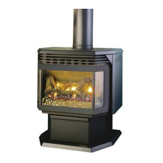
Freestanding Direct Vent Gas Stove
Installation and Operating Instructions
GTX-I
45282
Advertisement
Table of Contents

Related Manuals for Drolet GTX-I


Summary of Contents for Drolet GTX-I
- Page 1 Installation and service must be performed by a qualified installer, service agency or the gas supplier. Please read this manual before installing or using this appliance. Retain this manual for future reference. GTX-I Natural Gas or Propane Installation and Operating Instructions...
-
Page 2: Table Of Contents
... 23 4.4 Burner & pilot cleaning 4.5 Fan installation ... 24 5.0 TROUBLE SHOOTING 6.0 REPLACEMENT PARTS DROLET LIMITED LIFETIME WARRANTY Stove Builder International Inc. 1700 Rue Léon-Harmel Québec, PQ Canada G14 4R9 Tel. 418-527-3060 Fax : 418-527-4311 E-mail : client@sbi-international.com Table of content ... -
Page 3: Introduction
Variable Speed (120v / 60hz) REGISTER YOU WARRANTY ONLINE To receive full warranty coverage, you will need to show evidence of the date you purchased your stove. Keep your sales invoice. We also recommend that you register your warranty online at www.drolet.ca... - Page 4 APPLIANCE DIMENSIONS 26 1/16" 19 5 16 " 20 11 16 " 30 1/2" 29 1/16" Figure 1 INSTALLATION CODES Installation must conform to local codes. In the absence of local codes, installation must conform to the National Fuel Gas Code, ANSI Z233.1 1988, (in the U.S.), or with the current installation code CAN/CGA B149.1 –...
-
Page 5: Features
This appliance is intended to be used as a free standing heater. Massachusetts, the GTX-I may be installed in the United States and Canada in a bedroom or mobile home provided that CR89-00 and/or ANSI A225.1/NFPA 501A standards are followed, all required clearances are met, a wall thermostat is installed and where the maximum input is within 50 cubic feet of room volume per 1000 BTU/hr, (i.e.1500 minimum cubic feet) and the stove must be hooked... -
Page 6: Operation
2.0 OPERATION 2.1 Operation safety Inspect the appliance before use. Always keep the appliance area clear and free from combustible materials, gasoline, and other flammable vapors and liquids. Never obstruct the flow of ventilation air. Keep the front of the appliance clear of all obstacles and foreign materials. Never obstruct or modify the air inlet/outlet grilles of the fireplace in any manner. -
Page 7: Lighting Instructions
2.2 Lighting instructions FOR YOUR SAFETY, READ BEFORE LIGHTING WARNING: If you do not follow these instructions exactly, a fire or explosion may result causing property damage, personal injury or loss of life. This appliance has a pilot which must be lighted by hand. When lighting the pilot, follow these instructions exactly. BEFORE LIGHTING smell all around the appliance area for gas. -
Page 8: Heat Output Adjustment
2.3 Heat output adjustment The valve supplied with the appliance has a HI/LO knob to control the heat output and flame height (see Figure 2). 2.4 Fan operation The fan control knob is located on the control panel and may be adjusted to the following settings: OFF: Turn the control fully counter-clockwise until the switch operates. -
Page 9: Installation
3.0 INSTALLATION 3.1 Installation and safety notes Read all instructions before starting installation and follow them carefully during installation to ensure maximum benefit and safety. Failure to follow these instructions will void your warranty and may present a fire hazard. See the warranty at the back of this manual for disclaimers regarding improper installation. -
Page 10: Gas Line Installation
3.3.2 Gas line installation Install supply line using any piping approved for your installation meeting CAN/CGA 6.10, AA 3, ANSI Z21.24 or Z21.45. A qualified gas fitter should install the gas line in accordance with all local building codes. If codes permit, coiled copper tubing may be used for gas supply. Pressure taps are provided on the gas control for test gauge connections to measure the manifold and inlet pressures. - Page 11 TABLE 2: THERMOSTAT WIRE INFORMATION 2. Solder an appropriate wire connector to each wire. To connect to the burner switch, 1/4" female quick connects are required and to connect directly to the valve use spade tongue connectors. 3. Check tests can be performed on the valve by referring to the trouble shooting guide. WIRE SIZE MAX.
-
Page 12: Vent Installation
3.3.4 Vent installation 3.3.4.1 Acceptable configurations The stove must be connected to Simpson GS Dura Vent or Security Chimneys International (Secure Vent) 4” x 6 5/8” venting. Install the vent components according to the manufacturer's instructions. Use a maximum of two 90 degree elbows and four 45 degree elbows. Slope horizontal pipe at least 1/4"... - Page 13 The minimum vertical length using the maximum horizontal length consists of: • A minimum of 24” (61cm) vertical length directly on top of the stove. • A maximum of one 90 degree elbow. • A maximum of 12” (31cm) total horizontal length.
- Page 14 3.3.4.2 Typical vent installation Vent terminals shall not be recessed into a wall or siding. Figure 5...
- Page 15 Use a sealing product, available from your local Drolet dealer, on the inner pipe joint, applying the sealant around the outside of the male part of the vent. A bead of silicone should be used on the outside of the joint after assembly to seal the supply air.
- Page 16 The position of the horizontal vent termination must be positioned in such a way as to meet all local building codes. Attach the correct length of vertical section pipe and an elbow fitting to the stove. Mark the center line of the pipe facing the wall (allowing for a 1/4”...
- Page 17 Basement Installations To achieve the minimum vertical rise a 36” snorkel must be used. Where the bottom of the terminal may be blocked by snow, ensure provision is made for adequate drainage. 3.3.4.5 Vertical installation Always maintain a 1” clearance around the vent pipe (vertical) and 2” clearance horizontal, when passing through ceilings, walls, roofs, enclosures, attic rafter or any combustible surfaces.
- Page 18 Through Roof Framing Maintain 10” opening relative to the pitch of the roof. Use a suitable round or square support through the roof. Ensure adequate heat shield protection is provided. Termination above Roof Consult local codes for minimum vent cap height above the roof . To prevent water seepage;...
- Page 19 3.3.4.6 Vent terminal locations A = clearances above grade, veranda, porch, deck, or balcony [* 12" (305 mm) minimum] B = clearance to window or door that may be opened [* 12" (305 mm) minimum] C = clearance to permanently closed window [minimum 12" (305 mm) recommended to prevent condensation on window] D = vertical clearance to ventilated soffit located above the terminal within a horizontal distance of 24"...
- Page 20 3.3.5 Installation of the logs Note: If the pictures in this section are not clear enough, you may see them in color by downloading this owner’s manual via Drolet’s web site at www.drolet.ca Step 1 Step 3 Step 6 Step 2...
- Page 21 3.3.6 Initial firing At the time of the first burn, the appliance may emit an odor, accompanied by smoke. This is perfectly normal. As the metal heats to the critical point (about 375 degrees F), part of the paint components turns to light gray smoke as the dormant silicone resin activates and begins to bond with the metal.
- Page 22 3.3.7 Altitude adjustment All valves have been pre-set and certified for installation at elevations from 0 – 4500 feet (1 – 1372m) above sea level. When installing this heater at higher elevations, it is necessary to decrease the input rating by replacing the existing burner orifice with a smaller size for installations over 4500 feet (1372m).
-
Page 23: Maintenance
4.0 MAINTENANCE 4.1 Maintenance safety Turn off the gas to the main burner and allow the heater to cool for up to 30 minutes before servicing. Service and repair should be done by a qualified service person. The appliance should be inspected before use and at least annually by a professional service technician. -
Page 24: Burner & Pilot Cleaning
4.4 Burner & pilot cleaning Periodic cleaning is necessary for proper operation. Remove the burner, and check that the burner orifice is clean. Visually inspect the pilot. Brush or blow away any dust, lint, or foreign debris. If the pilot orifice is plugged, disassembly may be required to remove any foreign material from the orifice or tubing. -
Page 25: Trouble Shooting
5.0 TROUBLE SHOOTING SYMPTOM Pilot will not light after repeated triggering of the piezo ignition button II. Pilot will not stay lit after following the lighting instructions POSSIBLE CAUSE A. No spark at electrode (weak or not heat source for pilot ignition) 1. - Page 26 III. Main burner will not light IV. Soot deposits on glass Flame burns blue and lifts off burner VI. Flames impinge on firebox A. Valve / Switches 1. Valve control off 2. Blockage at the burner (line, orifice, or ports) 3.
-
Page 27: Replacement Parts
When requesting service or replacement parts, refer to your dealer. The following information’s will be asked for; the model name GTX-I, the type of gas used, serial number and proof of purchase. The damaged parts must be replaced by Drolet genuine parts. You can consult the spare parts list on our website at www.drolet.ca... -
Page 28: Drolet Limited Lifetime Warranty
Paint (peeling) and gaskets *Pictures required Shall your unit or a components be defective, contact immediately your DROLET dealer. Prior to your call make sure you have the following information necessary to your warranty claim treatment: •...