
Related Manuals for BBE DS48


Summary of Contents for BBE DS48
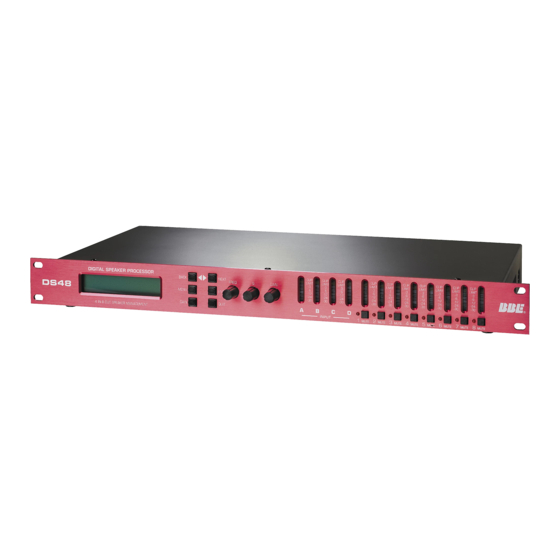
- Page 1 DIGITAL SPEAKER PROCESSOR DS48 •User Guide •Reference Manual professional products...
- Page 2 IMPORTANT SAFEGUARDS ®...
-
Page 3: Table Of Contents
7.6.1.5 HPF ………………………………………………………………11 7.6.1.6 LPF ………………………………………………………………11 7.6.1.7 PEQ ………………………………………………………………12 7.6.1.8 Limiter ……………………………………………………………12 7.6.1.9 Name of channel ………………………………………………13 7.6.1.10 Input Signal ……………………………………………………13 7.6.1.11 Copy Output Data ……………………………………………13 7.7 DS48 BLOCK DIAGRAMS ………………………………………………14 8 Graphical User Interface (GUI)…………………………………………………19 8.1 MINIMUM SYSTEM REQUIREMENTS …………………………………19... - Page 4 If any of these items are found to be damaged or missing, immediately contact the BBE dealer you purchased it from. This manual will help you to effectively utilize the BBE DS48. Reviewing the information contained in this manual will answer most of the common questions that our service department receives.
-
Page 5: Ds48 Features
DS48 FEATURES • 4 inputs 8 outputs and includes 10 configurations Crossovers • Choice of Operating and Crossover Modes: 4 X 2-way, 2 X 3-way + 2 Aux, Parametric 2 X 4-way, 1 X 5-way + 3 Aux, Mono Dist., Stereo Dist., LCRS w/Mono... -
Page 6: Introduction
You can also reduce the amount of outboard gear that is required to transport, set-up and operate as part of the sound system. The DS48 offers many powerful functions. It is highly recommended that you read through this manual before you begin connection and operation. For... -
Page 7: What Is A Speaker Management System
These functions include crossover, equalization, delay, limiting, high-pass and low-pass filtering as well as signal distribu- tion. Programs may be created, selected and edited with the DS48's front panel controls. However, to create new programs, it is best to use the included free PC software and configure the programs using the graphical user interface (GUI) and a Windows PC. -
Page 8: Front Panel
FRONT PANEL ® 1. LCD Display The 2x20 backlit LCD displays the program and programming choices of the unit. 2. <BACK/NEXT> Buttons These buttons allow navigation for selection of sub-menus and some parameter values. 3. Menu This is one of two buttons that will access the front panel programming. This one is used primarily to select which program to call up, edit or save. -
Page 9: Rear Panel
2. RS232 Interface Connect this to the serial port on a PC using the included cable or other standard DB-9 type cable. With the software installed, the PC can now monitor and program the DS48. 3. XLR Outputs 1-8 These are balanced (Pin 2 Hot) XLR outputs. -
Page 10: Quickstart
Before hooking up the system, make sure that all items are OFF, especially the power amps. Use high quality balanced XLR mic cables to make the connections. The feeds from the DS48 at "front of house" can also be sent through the audio snake returns to the amp stacks if used in a live setting. - Page 11 QUICK START Depending on the mode selected, other options will appear for this level of the menu, primarily concerned with input and output assignments. Some assignments are fixed with the crossover type selected. Only those assignments that can be selected will show on the display. Either the BACK/NEXT (2) buttons or the Parameter dial will work for stepping through the selections.
-
Page 12: Installation
6.1 RACK MOUNTING The DS48 fits into one standard 19” rack unit of space. Please allow at least an addition- al 4” depth for the connectors on the back panel. Though this device does not generate significant heat, be sure that there is enough air space around the unit for cooling. -
Page 13: Operation
2.The second method uses the included Graphical User Interface (GUI) software run on a Windows PC. The computer connects to the DS48 and gives a more global view of the parameters and the choices for settings. -
Page 14: Submenus
7.2.1.4 Store a Xover: Store all the configuration settings of a X-OVER. The DS48 will store up to 30 program configurations in user memory locations. (An unlimited number can be stored on a PC or other PC accessible memory.) Each of the 30 programs can have a name containing up to 16 letters and numbers. -
Page 15: Subsystem Submenu
OPERATION Press MENU, NEXT and ENTER. Then use the NEXT/BACK and ENTER buttons to adjust the Security Submenu. The various locking modes are as follows: 1. LOCK: Changes only: Parameters can be viewed, but cannot be adjusted. MUTE buttons are valid. 2. -
Page 16: Interface Submenu
Press MENU, then NEXT three times and then ENTER. Use the BACK/NEXT or FREQ knob to enter an ID value between 1 and 64. Use this function when multiple DS48 units are used. Master Control unit is set as 1; slave units are set with subsequent numbers. -
Page 17: Polarity
71 degree Fahrenheit dry air at sea level is ~773miles per hour. This is ~345 meters per second and about 1.13 feet per millisecond. .5 milliseconds equates to about 6.78 inches. .1 milliseconds equates to about 1.36”. The DS48 displays 1ms = 343mm = 1.1ft. -
Page 18: Peq
OPERATION ® filter type and slope. Rotate the FREQ knob to select the frequency and the Q knob to select the filter type. HiPass: frequency range 10Hz~16.0KHz LoPass: frequency range 35Hz~22.0KHz Use HPF and LPF together to define the frequency band for this channel of the crossover. -
Page 19: Name Of Channel
The time should be chosen care- fully as the danger of dynamics distortion usually increases with shorter attack times. The attack time of the DS48 can be set within a range of 1 to 100 millisec- onds. -
Page 20: Ds48 Block Diagrams
GAIN MUTE OUTPUT 3 GAIN PEQS Delay GAIN MUTE OUTPUT 4 INPUT D HIGH PEQS Delay GAIN MUTE OUTPUT 4 DS48 4X2 WAY GAIN PEQS Delay GAIN MUTE INPUT A OUTPUT 1 PEQS Delay GAIN MUTE OUTPUT 1 HIGH PEQS... - Page 21 BLOCK DIAGRAMS GAIN PEQS Delay GAIN MUTE OUTPUT 1 INPUT A PEQS Delay GAIN MUTE OUTPUT 1 HIGH PEQS Delay GAIN MUTE OUTPUT 1 GAIN PEQS Delay GAIN MUTE INPUT B OUTPUT 2 PEQS Delay GAIN MUTE OUTPUT 2 HIGH PEQS Delay GAIN...
- Page 22 BLOCK DIAGRAMS ® GAIN PEQS Delay GAIN MUTE INPUT A OUTPUT 1 LOW MID PEQS Delay GAIN MUTE OUTPUT 1 HIGH MID GAIN PEQS Delay GAIN MUTE OUTPUT 1 INPUT B HIGH PEQS Delay GAIN MUTE OUTPUT 1 PEQS Delay GAIN MUTE GAIN...
- Page 23 BLOCK DIAGRAMS GAIN PEQS Delay GAIN MUTE INPUT A OUTPUT 1 PEQS Delay GAIN MUTE OUTPUT 2 LOW MID GAIN PEQS Delay GAIN MUTE INPUT B OUTPUT 1 LOW MID PEQS Delay GAIN MUTE OUTPUT 2 HIGH MID PEQS Delay GAIN MUTE OUTPUT 1...
- Page 24 BLOCK DIAGRAMS ® GAIN PEQS Delay GAIN MUTE INPUT A OUTPUT 1 PEQS Delay GAIN MUTE OUTPUT 2 GAIN PEQS Delay GAIN MUTE INPUT B OUTPUT 3 PEQS Delay GAIN MUTE OUTPUT 4 MUTED PEQS Delay GAIN MUTE GAIN OUTPUT 5 INPUT C MUTED PEQS...
-
Page 25: Graphical User Interface (Gui)
GRAPHICAL USER INTERFACE (GUI) The BBE SYSOMAX software provides a graphical method of creating and editing programs on the DS48. It can also be used to make changes in real time, if adjustments are required during live operation. Full metering and control of all settings is available on the PC. -
Page 26: Starting Up Sysomax
7. When the installation is complete, eject the CD-ROM 8.3 STARTING UP SYSOMAX To create a preset program on a DS48 unit , first connect it to the computer with the seri- al cable. If your computer only has USB ports, adapters are available from computer sup- pliers. -
Page 27: Top Line Menu
1. Exit lets you select EXIT to exit the program. 2. Config provides six choices: A. Online, which will open the RS-232 connection to the DS48 when it’s prop- erly connected. B. Offline, which will close the connection to the unit. -
Page 28: Device Program Manage/Memory
GRAPHICAL USER INTERFACE (GUI) ® Device Program Manage/Memory Clicking the Memory icon or selecting Device Program Manage form the Program Menu will open a dialog box with a table displaying 30 memory locations and spaces for names as well as 10 buttons. To Store a program as a memory location, click on the desired Prog line in the table for the desired save location. -
Page 29: Lock Unit
GRAPHICAL USER INTERFACE (GUI) Erase All will erase all programs in the memory table and in the device. There is a confirm screen before this command executes. Exit will close the window. Lock Unit Found under config dropdown menu Provides four options for security lockouts in the pull-down menu. Make your selec- tion and enter your password in the text box. -
Page 30: Creating A Program
CREATING A PROGRAM ® Once the device type and crossover type have been selected, the main screen will show blocks for each programmable section. This is referred to as the “Flow Chart”. The term “program” is used here as an equivalent to “preset”... -
Page 31: Gains
CREATING A PROGRAM Whenever any screen windows, other than the main one, are displayed, the top-level menu will be disabled until the window is closed. To close a win- dow, hit the escape key (esc) or Exit in the window. When entering values into text boxes you can use your pointing device such as a mouse or touchpad. -
Page 32: Delays
CREATING A PROGRAM ® 9.2 DELAYS: Clicking the Delays tab will open the Delays window. There is a text box for each output and a display Units selector. The Units selector gives you a choice of whether the delay is expressed in mil- liseconds, feet or meters. -
Page 33: Out 1, Out 2, Etc
CREATING A PROGRAM 9.4 OUT 1, OUT 2, etc. Each tab selects an output channel. Use this screen to program crossover frequencies, filter type, and up to five parametric EQ’s. In addition, the same programming choices as on the GAIN screen are duplicated here, but just for the selected output channel. - Page 34 Incorrect settings or mis-wiring (sending lows to a HF driver for instance) can damage or destroy your equipment. BBE Sound is not liable for any direct or consequential damages caused by improper use of its equipment.
-
Page 35: Parametric Equalizers
CREATING A PROGRAM 9.6 Parametric Equalizers: The next set of text boxes provides Frequency, Gain and Q setting choices for five bands of parametric equalization (PEQ) per output channel. There is also a check box for Flat, which will bypass the settings for that particular filter. In a similar manner to the Crossover filters above, clicking on any text box will open the PEQ filter settings window. -
Page 36: Specifications
SPECIFICATIONS ® BALANCED INPUTS Input Impedance ………………10KOhms CMRR …………………………50dB (30Hz~20KHz) As standard, the DS48 comes Output Impedance ……………<50Ohms Maximum output electrical level Vpp=7.6V with electronically servo-bal- Frequency Resp ………………20Hz~20.0KHz anced inputs. This circuit design Dynamic Range ………………110dB (A weighted) features automatic hum and Distortion ………………………0.01%(THD) -
Page 37: Service
Sound, Inc. directly at (714) 897-6766, extension 116 to obtain a “RETURN AUTHORIZA- TION”. Include a copy of the bill of sale with the unit when it is shipped to BBE Sound, Inc. so that the service can be expedited. -
Page 38: Maintenance
All non-warranty repairs are warranted for a period of 90 days from the date of service. BBE Sound, Inc. is NOT LIABLE FOR CONSEQUENTIAL DAMAGES. Should the unit fail to operate for any reason, our sole obligation is to repair it as described above. - Page 39 ® 5381 Production Drive Huntington Beach, CA 92649 714-897-6766 • FAX 714-896-0736 www.bbesound .com BBE is the registered trademark of BBE Sound, Inc. rev. 1 3/2006...