ACR Electronics NAUTICAST INLAND AIS User Manual
Hide thumbs
Also See for NAUTICAST INLAND AIS:
- Manual (108 pages) ,
- Installation manual (100 pages) ,
- Manual (104 pages)
Chapters
Table of Contents

Related Manuals for ACR Electronics NAUTICAST INLAND AIS


Summary of Contents for ACR Electronics NAUTICAST INLAND AIS
- Page 1 AUTOMATIC IDENTIFICATION SYSTEM - INLAND User Manual P/N 2662 ACR Electronics, Inc. 5757 Ravenswood Road Fort Lauderdale, Fl 33312 +1(954) 981-3333 Fax +1 (954) 983-5087 www.acrelectronics.com Email: Info@acrelectronics.com Y1-03-0211...
- Page 2 Please read this first! Warning: Although ACR strives for accuracy in all its publications; this material may contain errors or omissions, and is subject to change without prior notice. ACR shall not be made liable for any specific, indirect, incidental or consequential damages as a result of its use. ACR components may only be used in safety of life devices or systems, with the express written approval of ACR, as the failure of such components could cause the failure of the ACR device or system.
-
Page 3: Table Of Contents
NAUTICAST Inland AIS Transponder User Manual Index Page Number NAUTICAST..................................4 TARTING THE Initial Set Up of the NAUTICAST for operation...........................4 Entering the MMSI / IMO / DAC / ESN Numbers........................5 Entering Ship Settings ................................8 Entering Voyage Related Data ..............................10 Service and User Passwords..............................14 NAUTICAST U ................................17... - Page 4 History of Changes Date Version Rev. Status Comments Responsible 2005-11-01 1.0.0 Released Initial Release A. Lesch 2006-07-25 1.0.1 Released Editorial work M.D’Arcangelo User Manual Y1-03-0211 Rev. B...
-
Page 5: Starting The Nauticast
1 Starting the NAUTICAST 1.1 Initial Set Up of the NAUTICAST for operation ATTENTION: AUTHORITIES MANADATE THAT YOU ENTER THIS INFORMATION. After installing the antennas and hardware the following User, Voyage related and Ship Settings data needs to be entered. Upon Start-up (Applying power) enter the following information. -
Page 6: Entering The Mmsi / Imo / Dac / Esn Numbers
1.2 Entering the MMSI / IMO / DAC / ESN Numbers Select from the Main Menu “Service Configuration” Number 6. Menu is SERVICE password protected with default password “NAUT”. Enter Service Password and use the up and down arrows on keypad to select “Change MMSI / IMO” than press M5 “Select” or “by pressing number 3 on the keypad. - Page 7 N 1^21' E 0^14' |1> N/A|2>0.00|3>0.10nm ********** Change MMSI / IMO *********** MMSI :1193046 IMO No.:303174162 ---------------------------------------- NUM| Save | Back Select Submenu 4 “Change DAC / ESN” with cursor button [Up] & [Down] by pressing Nr. 4 on the keyboard. N 1^21' E 0^14' |1>0.01|2>1.30|3>1.80nm |----------------------------------...
- Page 8 Input new DAC / ESN Numbers and press [Save] to store input data. Press [Back] to return to the Submenu without saving. Note: The DAC (Designated Area Code) is predefined with the value “200”. Please key in only a different 3 digit value if your authority wants you to do this. Otherwise you may lose important AIS information.
-
Page 9: Entering Ship Settings
1.3 Entering Ship Settings Select from the Main Menu “Ship Settings” Menu is USER password protected with default password “NAUT”. Enter Password and use the up and down arrows to edit Ship Settings then press Enter or the numeric reference on the keypad to select and edit. Save after editing. - Page 10 Setting the Internal and External GPS Antenna Position. Note: It is critical for the proper orientation of your ship to other AIS users to enter this data accurately. Example: Length of ship / convoy = 220m and Beam of ship / convoy = 43m. GPS ANTENNA location on ship (is x in above Menu example) is located 200 meters from bow (A) and 33 Meters from Starboard side (D).
-
Page 11: Entering Voyage Related Data
1.4 Entering Voyage Related Data Select from the Main Menu “Voyage Settings” Menu is USER password protected with default password “NAUT”. Enter Password and use the up and down arrows to edit Voyage Related data then press Enter or the numeric reference on the keypad to select and edit. Save after editing. - Page 12 The password query field appears. Input new User Password and press [Enter]. N 1^31' E 0^24' |1>0.01|2>1.30|3>1.80nm ---------------------------------------- ++++++++++++++++++++++++++++++++++++++++ User password protected! Please enter user password: ++++++++++++++++++++++++++++++++++++++++ ---------------------------------------- | Enter | Exit N 1^18' E 0^12' |1>0.01|2>1.30|3>1.80nm |---------------------------------- | 3. Voyage Settings -----| | | +- 1.
- Page 13 N 1^18' E 0^12' |1>0.01|2>1.30|3>1.80nm ***********General Settings************* SOLAS Draught:>=25.5m INLAND Draught:=>2000cm Airdrauht :=>4000cm NavStat. :<under way using engine> BlueSign : used ---------------------------------------- Save | Exit Select Submenu 2 “Cargo/Voyage Settings” with cursor button [Up] & [Down] or by pressing Nr. 2 on the keyboard. Toggle the values for the ERI ship type, the hazardous cargo (number of blue cones) and the loaded / unloaded status.
- Page 14 Select Submenu 3 “Persons on Board” with cursor button [Up] & [Down] or by pressing Nr. 2 on the keyboard. N 1^18' E 0^12' |1>0.01|2>1.30|3>1.80nm ************* PoB Settings ************* Crew Members:0-254 (255 = unknown = default) Passenger :0-8190(8191= unknown = default) S.
-
Page 15: Service And User Passwords
1.5 Service and User Passwords The Transponder system is equipped with two levels of Password Protection, User and Service Password. 1) The User Password, which is the lower security level, allows access to all menus except Menu 6: Service Configuration which is protected by the Service Password. 2) The Service Password is required in order to enter the Service Configuration Menu. - Page 16 Service Menu Example: N 1^21' E 0^14' |1>0.01|2>1.30|3>1.80nm |---------------------------------- | 6. Service Configuration -----| | | +- 1. Change Service Password View | +- 2. User Password Settings | +- 3. Change MMSI / IMO -----| +- 4. Restore Factory Settings Msg.
- Page 17 N 1^21' E 0^14' |1>0.01|2>1.30|3>1.80nm |---------------------------------- | 6. Service Configuration -----| | | +- 1. Change Service Password View | +- 2. User Password Settings | +- 3. Change MMSI / IMO -----| +- 4. Restore Factory Settings Msg. | -----| Displ| ----------------------------------------...
-
Page 18: Nauticast User Interface
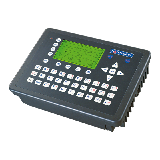
NAUTICAST User Interface Display Safety Keys Soft Keys [M1] – [M8] Navigation Screen Header (1 or 4 lines) _________________ Ship Details 12 lines Menu Structure 14 lines Keyboard Cursor Cross Enter Key User Manual Y1-03-0211 Rev. B... -
Page 19: Nauticast Keyboard
2.1 NAUTICAST Keyboard The NAUTICAST is fitted with a full alphanumeric keyboard, with the following functions: By pressing any key on the keyboard the letters are addressed. Number symbols and special characters are addressed by holding down the shift [ ] key and simultaneously pressing the chosen key. The characters ($;... -
Page 20: Explanation Of The Soft Keys
2.4 Explanation of the Soft Keys The Soft Keys are divided into vertical static keys [M1-M4] and horizontal dynamic keys [M5- M8], which differ in function according to the current application. Soft Key Definition filter option on AIS targets in graphical view •... -
Page 21: Nauticast Screens
3 NAUTICAST Screens NAUTICAST The advanced version of the offers three display modes: - Standard screen, automatically visible Navigation Screen - Visible after pressing the [Menu] Soft Key Menu Structure - The Graphical User Interface is visible after pressing the [M2] Soft Graphical User Interface Key (new mode) 3.1 Navigation Screen... -
Page 22: Own Vessel Data
3.1.1 Own Vessel Data LAT:N 1°27.845'ExtSOG:34.6kn 05/26/06 LON:E 0°21.289'IntCOG:173.0° 10:52:26 LAT: Latitude LON: Longitude The actual UTC - date (MM.DD.YY) and time (hh.mm.ss) are displayed on the top Date: right hand corner of this view. IntGPS: 3D ExtHDT:222° Reg6 IntGPS Indicates normal or differential mode of GPS position. -
Page 23: Other Vessel Data
The “RTA” indicates a received Requested Time of Arrival. The content of this message could be seen in the Message Menu. Inland Indication BlueSign: ON **RTA** AISMode: INLAND The AIS-Mode indicator shows the actual configured mode of the NAUTICAST. The NAUTICAST could be used as INLAND AIS and as SOLAS Product. -
Page 24: Short Header
3.1.3 Short Header A constant overview of the most important AIS navigation details, including own position and distance of the three closest vessels is always displayed the first line. This information appears in every Submenu and is called the “Short Header”. N 1^21 E 0^14' |1>0.10|2>1.30|3>1.80nm Own Vessel Position: N 1^21' E 0^14'... - Page 25 Heading :77^ ROT :-0.2^/min l IMO-Number and MMSI of the selected vessel: IMO No. : 90733283 MMSI: 5004 Name and CallSign of the selected vessel: ShipName:DOREEN CS:DORET6W Vessel Type Passenger ship Length and Beam of the selected vessel: Length:310m Beam:73m Reference Point (in meters): This information indicates the Reference Point of the used GPS Antenna onboard the vessel.
- Page 26 PosAcc :High <10m DTE :Available This information indicates that the vessels Transponder is connected with a user interface and can show AIS Data. This function basically ensures that the current Transponder being used is fitted with a display and can therefore send and receive messages. As the NAUTICAST is fitted with an integrated display unit, it will always show “DTE: Available”.
-
Page 27: Menu Structure
Menu Structure To call up the Main Menu, press the [Menu] button once, and all Submenus are displayed. The cursor position indicates the selected submenu. Menu navigation is achieved by pressing the [Up] or [Down] keys to select, and then by pressing [Enter] to confirm the desired Submenu selection. -
Page 28: Sub-Menus Overview
Sub-Menus Overview 3.4.1 Messages N 1^19' E 0^12' |1>0.10|2>1.30|3>1.80nm |---------------------------------- | 1. Messages -----| | | +- 1. Write Addressed SRM View | +- 2. Write Broadcast SRM | +- 3. Lock Request -----| +- 4. Inbox History | +- 5. Inbox SRM Msg. -
Page 29: Voyage Settings - (User Password Protected)
3.4.3 Voyage Settings – (User Password Protected) N 1^18' E 0^12' |1>0.01|2>1.30|3>1.80nm |---------------------------------- | 3. Voyage Settings -----| | | +- 1. General Settings View | +- 2. Cargo / Voyage | +- 3. Persons on Board -----| +- 4. Destination Msg. -
Page 30: Transponder Configuration - (User Password Protected)
3.4.5 Transponder Configuration – (User Password Protected) N 1^19' E 0^12' |1> N/A|2>0.00|3>0.10nm |---------------------------------- | 5. Transponder Configuration -----| | | +- 1. Change User Password View | +- 2. Region Settings | +- 3. Alarm Settings -----| +- 4. Interrogation Settings | +- 5. -
Page 31: Display Settings
3.4.7 Display Settings N 1^21' E 0^15' |1>0.10|2>1.30|3>1.80nm *********** Display Settings *********** Mode +-[*] Day +---- Brightness:<9> [*********] +---- Contrast [****** +-[ ] Night +---- Brightness: 3 [*** +---- Contrast ---------------------------------------- NUM|DayNight| | Back 3.4.8 Graphical Display Settings N 1^46' E 0^39' |1>0.10|2>1.30|3>1.80nm |---------------------------------- | 8 Graphical Display Settings... -
Page 32: Sub-Menus Detailed
Sub-Menus Detailed 3.5.1 Messages N 1^19' E 0^12' |1>0.10|2>1.30|3>1.80nm |---------------------------------- | 1. Messages -----| | | +- 1. Write Addressed SRM View | +- 2. Write Broadcast SRM | +- 3. Lock Request -----| +- 4. Inbox History | +- 5. Inbox SRM Msg. - Page 33 Message Storage Capacity: The Inbox History has the capacity to store a total of 60 messages. The older messages are automatically deleted, when the respective Inbox has reached its maximum storage capacity. Message Type: Maximum Storage Capacity: Addressed or Broadcast Messages (SRM): Latest 30 Messages stored Alarms (ALR): Latest 20 stored Long Range Interrogation (LRI):...
- Page 34 b) Using the NAUTICAST Message Editor After selecting a vessel, the Message Editor is automatically displayed. Messages containing a maximum of 156 characters are allowed. Longer texts require a second message. After text input completion, transmission to the selected addressee is facilitated by pressing the [Send] button.
- Page 35 c) Confirmation of Sent Addressed Message The confirmation screen shows the successful message transmission and indicates which channels (AIS1 or AIS2) were used. Successful Message Transmission on Channel AIS1: LAT:N 1^18.963'ExtSOG:34.6kn 11/21/2002 LON:E 0^12.408'IntCOG:173.0 09:11:08 Ships:21 /B IntGPS: 3D Region6 ++++++++++++++++++++++++++++++++++++++++ Transmission Status [+] AIS1:OK, acknowledgement received...
- Page 36 It is possible, that the recipient’s Transponder could not receive the message at all, and in this case the following screen is displayed. It is then recommended to resend the message. Unsuccessful Message Confirmation (no acknowledgement) N 1^19' E 0^12' |1>0.10|2>1.30|3>1.80nm ---------------------------------------- ++++++++++++++++++++++++++++++++++++++++ Transmission Status...
- Page 37 d) Writing a Broadcast Message Upon selection of Write Broadcast SRM in the Message Menu, the Message Editor appears. Messages containing a maximum of 161 characters are allowed. Longer texts require a second message. When the text input has been completed, transmission to all vessels within receiving range is possible by pressing the [Send] button.
- Page 38 e) Confirmation of Broadcast Sent Message This Confirmation Screen shows that the message was successfully transmitted on the Broadcast Setting. By pressing [Back] the user automatically returns to the Message Editor for further Messaging. The [SendTo] returns the user to the Vessel Listing, with the option of further Message Writing to individual vessels.
- Page 39 f) Long Range Interrogation Mobile, and shore-based stations have the ability to interrogate vessels and make requests for information over the “Long Range Interface”. The interrogated vessel can either reply in automatic, or in manual mode. The interrogation request is displayed in both modes. The arrival of a Long Range Interrogation Request is indicated by: 1L on the top right hand corner of the Navigation Screen.
- Page 40 An LRI has arrived; The NAUTICAST Settings are configured to Automatic Mode: N 1^20' E 0^13' |1>0.10|2>1.30| * ************** Inbox LRI *************** LRI *07:44 5004 07:44 11/28 ------------------ POS:01/01 LRI 5004 (automatic mode) Please confirm with OK! ---------------------------------------- Reply | Back >...
- Page 41 N 1^20' E 0^14' ||1>0.10|2>1.30| * ************** Inbox LRI *************** LRI *07:49 5004 07:44 5004 07:49 11/28 ------------------ POS:01/02 LRI 5004 (manual mode) Please acknowledge with OK/Reject! ---------------------------------------- | Reject Reply | Back Dynamic Keys: LRI in the Inbox History (manual mode) Send Addressed Accept LRI Message to LRI...
- Page 42 g) Inbox History The Inbox History provides a means to reading incoming messages and alarms. The messages are listed in chronological sequence. The message type (SRM, ALR or LRI), Status, Time, Message Text Preview and MMSI Number of sender are shown in this overview screen.
- Page 43 Inbox History: Message and Alarm Types and Status Definition: N 1^19' E 0^13' |1>0.10|2>1.30 * 1S1A ************ Inbox History ************* ASRM 13:43 PIRATE ATTACK! 5264 ASRM*13:42 HIGH WINDS IN AREA! 5004 13:40 external EPFS lost ALR!*13:38 general failure ALR! 13:39 no sensor pos in use26 13:43 11/21 ------------------ POS:01/05 AddressedSRM 5264...
- Page 44 N 1^26' E 0^20' |1>0.10|2>1.30|3>1.80nm ************** Inbox SRM *************** ASRM*17:39 CAPTAIN IS LOST 5004 ASRM 16:26 ROUGH SEA! 5022 17:39 11/26 ------------------ POS:01/02 AddressedSRM 5004 Text:CAPTAIN IS LOST Channel:AIS1 ---------------------------------------- Reply Back ASRM: Information Time 17:39 Date 11/26 (mm.dd) 01/02 (Message 01 of 02) Message Type AddressedSRM Status...
- Page 45 ALR – Reading Incoming Alarms: N 1^27' E 0^21' |1>0.10|2>1.30|3>1.80nm ************** Inbox ALR *************** ALR! 17:36 no valid COG information 17:36 11/26 ------------------ POS:01/01 [!] ALARM ID:30 no valid COG information ---------------------------------------- | Back ALR: Information Time 17:36 Date 11/26 (mm.dd) 01/1 Message Type ALARM...
- Page 46 h) Writing a “Estimated Time of Arrival” (ETA) Message Upon selection of “3. Lock Request” in the Message Menu, the Lock Request (ETA) Editor appears. The Message contains: The address of the recipient of this ETA – Message (the default is “2000000”). The address could be received from the authority.
- Page 47 Inbox of a received “Requested Time of Arrival” (RTA) Message Upon selection of “7. Lock Reply” in the Message Menu, the received Reply to your ETA – Message appears. The Message contains: The timestamp of this message in the format MM/DD hh:mm. The location code of the Lock The requested time of arrival at the lock in the format MMDDhhmm (month-day-hour- minute).
-
Page 48: Ais Status
3.5.2 AIS Status The AIS Status Menu provides a variety of information concerning own vessel settings, as well as the current AIS status of the other vessels, which are displayed in the Vessel Listing. Version Info provides details of the actual software release currently installed. Security Log traces the downtimes of the Transponder, to ensure those periods of down time when the transponder is out of order or lacking electricity can be traced. - Page 49 k) State / Conditions This screen provides a means to viewing the current AIS status of all vessels within receiving range. The information reported is own vessel’s last AIS contact with the other vessel in the listing (Time), the Transponder mode (Mod.), the synchronization status (Syn.) and the total number of vessels being received by each vessel in the listing (RXVe).
- Page 50 Own Ship Data This screen shows own Ship, and Voyage Data, which was previously input in Menu 3: Ship Settings and Menu 4: Voyage Settings. N 1^26' E 0^19' |1>0.10|2>1.30|3>1.80nm Time 0:08 ------------------------------ 1^18.901'LON :E 0^12.345' Heading :222^ ROT :+5.4^/min r IMO No.
- Page 51 Indicates the type of cargo on board N/A or harmless Further Vessel Details: Draught : 3.3m Dest : HAWAII : 10/15 12:31 NavSt : Moored Information on the vessel’s Equipment Position Finding Device: EPFDType: GPS Position Accuracy and Data Terminal Equipment (DTE): PosAcc :High <10m DTE :Available...
- Page 52 m) Version Info This Screen shows the actual Software Release which is being run on the NAUTICAST. N 1^22' E 0^16' |1>0.10|2>1.30|3>1.80nm ************* Version Info ************* ### ### # # # # ## #### # #### ##### # # ### # ### Hardware: Inland AIS Transponder Software: 2.0.n.n...
-
Page 53: Voyage Settings (User Password Protected)
3.5.3 Voyage Settings (User Password Protected) Select the “Voyage Settings” – Sub Menu from the Main Menu with the cursor button [Up] & [Down] or press Nr. 3 on the keyboard Note: The default User Password is set to “NAUT” – please reconfigure it immediately after Transponder initial operation N 1^20' E 0^13' |1>... - Page 54 N 1^18' E 0^12' |1>0.01|2>1.30|3>1.80nm |---------------------------------- | 3. Voyage Settings -----| | | +- 1. General Settings View | +- 2. Cargo / Voyage | +- 3. Persons on Board -----| +- 4. Destination Msg. | -----| Displ| ---------------------------------------- NUM|Select->| |<-Back Select Submenu 1 “General Settings”...
- Page 55 Select Submenu 2 “Cargo/Voyage Settings” with cursor button [Up] & [Down] or by pressing Nr. 2 on the keyboard. Toggle the values for the ERI ship type (see Appendix), the hazardous cargo (number of blue cones [0-3, 4=B-Flag, 5=default=unknown]) and the loaded / unloaded status. Save the new settings by pressing [Save], and return to the Main Menu Screen by pressing [Exit].
- Page 56 N 1^19' E 0^12' |1> N/A|2>0.00|3>0.10nm ************** Send PoB **************** Broadcast PoB Message ---------------------------------------- auto/ A / B /A+B Channel: [*]/[ ]/[ ]/[ ] ---------------------------------------- Send |<Channel |Channel> | Back Dynamic Keys: Broadcast Message Editor Send Message Send Message [M5] [Send] [Enter] Select Transmission...
- Page 57 After the Voyage Settings have been input and saved, this screen appears. [Exit] takes the user back to the Main Menu. N 1^30' E 0^24' |1>0.10|2>1.30|3>1.80nm ---------------------------------------- ++++++++++++++++++++++++++++++++++++++++ Data saved. ++++++++++++++++++++++++++++++++++++++++ ---------------------------------------- | <-Exit User Manual Y1-03-0211 Rev. B...
-
Page 58: Ship Settings (User Password Protected)
3.5.4 Ship Settings (User Password Protected) Select “Ship Settings” with cursor button [Up] & [Down] or press Nr. 4 on the keyboard. Note: The default User Password is set to “NAUT” – please reconfigure it immediately after Transponder initial operation N 1^23' E 0^16' |1>0.01|2>1.30|3>1.80nm |----------------------------------... - Page 59 Example: Length (of the complete convoy) = 400m Beam (of the complete convoy) = 32m Internal GPS-Antenna is mounted 20 metres from stern and 24 metres from starboard. Length(Conv) : 400 Beam(Conv) : 32 RefPtExt RefPtInt : B20D24 (!! without spaces, no decimals, no commas !!) The full line as shown will be displayed after pressing Enter: RefPtInt : A380 B20 C8 D24m...
- Page 60 After the Ship Settings have been input and saved, this screen appears. [Exit] takes the user back to the Main Menu. N 1^30' E 0^24' |1>0.10|2>1.30|3>1.80nm ---------------------------------------- ++++++++++++++++++++++++++++++++++++++++ Data saved. ++++++++++++++++++++++++++++++++++++++++ ---------------------------------------- | <-Exit GPS Antenna Mounting It is important to input the exact mounting position of the GPS Antenna on the vessel as this influences the accuracy of the displayed target in an ECDIS.
-
Page 61: Transponder Configuration (User Password Protected)
3.5.5 Transponder Configuration (User Password Protected) The Configuration Menu allows the user to alter the hardware-based parameters. User Password Configuration is also undertaken here. Accessing the Configuration Settings: The Configuration Menu is User Password protected. Note: The default User Password is set at “NAUT” It is strongly recommended to change it immediately after commencing initial NAUTICAST operation! N 1^22' E... - Page 62 Accessing the Configuration Menu with the default User Password “NAUT” The letters of the Password appear as when being input on the screen. N 1^18' E 0^12' |1>0.10|2>1.30|3>1.80nm ---------------------------------------- ++++++++++++++++++++++++++++++++++++++++ User password protected! Please enter user password: **** ++++++++++++++++++++++++++++++++++++++++ ---------------------------------------- | Enter | Exit Dynamic Keys: Input of Default User Password to Access...
- Page 63 a) Change User Password (for initial NAUTICAST Operation) It is strongly recommended to change the default User Password upon initial NAUTICAST operation. The new User Password can be between 4 - 8 characters in length, and is not case sensitive. N 1^19' E 0^12' |1>0.10|2>1.30|3>1.80nm |----------------------------------...
- Page 64 N 1^19' E 0^13' |1>0.10|2>1.30|3>1.80nm ---------------------------------------- ++++++++++++++++++++++++++++++++++++++++ Passwords mismatched! ++++++++++++++++++++++++++++++++++++++++ ---------------------------------------- |<-Exit Dynamic Keys: User Password Input (Password Mismatched) Return to Password Input Screen [M5] [Exit] The new User Password configuration has been saved. N 1^33' E 0^27' |1>0.10|2>1.30| * 1A1L ---------------------------------------- ++++++++++++++++++++++++++++++++++++++++...
- Page 65 b) Region Settings A Region is a defined area, with specific VHF parameters, which are sent out by Vessel Traffic Service Stations (VTS), and received via Digital Selective Calling (DSC) or AIS. The screen shows a list of Regions, and their input sources. When the vessel enters into one of the pre-defined Regions, the NAUTICAST automatically switches to the relevant Region Setting.
- Page 66 Creating a New Region Parameters for setting up a new Region can be entered and saved here. N 1^19' E 0^12' |1>0.10|2>1.30|3>1.80nm ********** Create New Region *********** NE LAT(1):N 0^ 0.0000' +----------1 NE LON(1):E 0^ 0.0000' | +------+ | SW LAT(2):N 0^ 0.0000' SW LON(2):E 0^ 0.0000'...
- Page 67 This screen allows the user to enable or disable the generation and display of Alarms. Alarms are displayed in the Alarm Inbox (see Menu 5: Transponder Configuration, Submenu 3: Alarm Settings) and on the ECDIS screen. Note: It is highly recommended to enable the Alarm Function. N 1^19' E 0^12' |1>0.10|2>1.30|3>1.80nm ************ Alarm Settings ************...
- Page 68 d) Interrogation Settings This screen allows settings for modes of response to Long Range Interrogation Requests (LRI). It is possible to set the AIS station to respond automatically or manually to LR Interrogations, and determine which vessel data may be interrogated. It is further possible to reply to incoming LRI’s.
- Page 69 Replying to a Long Range Interrogation Request: The arrival of an LRI is shown in the Navigation Screen (top right hand corner: * 1L The detailed LRI is automatically stored in Menu 1:Messages, Submenu: 6 Inbox LRI, where the request can be read and replied to. LAT:N 1^20.261'ExtSOG:34.6kn LON:E...
- Page 70 e) Sensor Settings Within this service password protected menu the NAUTICAST offers the following configuration options: • Set up data speed 4800/9600/38400 baud. • Monitor the connected sensor inputs for each sensor channel. • Verify and edit the Sensor Configuration on the display screen. •...
- Page 71 f) Inland AIS Quality Information This screen allows the user to toggle the quality of the speed, course or heading information received from an external device. These settings are normally set to low. Note: It is highly recommended to keep the settings to low. N 1^22' E 0^16' |1>...
-
Page 72: Service Configuration (Service Password Protected)
3.5.6 Service Configuration (Service Password Protected) The Service Configuration Menu allows initial configuration of the Service Password, Password Settings (on/off), MMSI/IMO Numbers and the option of resetting the NAUTICAST to Factory Settings. The Service Password is required in order to enter the Service Configuration Menu. This is a higher security level than can be reached with the User Password and therefore ensures that the Service Configuration is protected, and limited to authorized service personnel. - Page 73 After entering the Default Service Password “NAUT”, in the password query, the Service Configuration Menu may be accessed. In this menu it is possible to configure both the Service Password and the User Password Settings, as well as input the MMSI/IMO Numbers and reset the to Factory Settings.
- Page 74 N 1^27' E 0^20' |1>0.10|2>1.30|3>1.80nm ******* Change Service Password ******** Enter new password :**** Repeat new password:**** {Length: 4..8 characters} ---------------------------------------- Save | Back Dynamic Keys: Change Service Password Save New Service Return to Submenu [Save] [M8] [Back] Password Service Configuration h) User Password Settings N 1^24' E 0^18' |1>0.10|2>1.30|3>1.80nm...
- Page 75 N 1^19' E 0^12' |1>0.10|2>1.30|3>1.80nm ****** Change Password Protection ****** on/off User password protection: [*]/[ ] Note: It is highly recommended that you enable user password protection. ---------------------------------------- Save | Change | Back Dynamic Keys: Change User Password Protection Save User Save User [M5] [Save]...
- Page 76 Changing the MMSI / IMO / DAC / ESN Numbers Mentioned DAC and ESN numbers are only available in Inland AIS - Mode . Select again “Service Configuration” from the Main Menu with the cursor button [Up] & [Down] or press Nr. 6 on the keyboard. Select Submenu 3 “Change MMSI/IMO”...
- Page 77 Select Submenu 4 “Change DAC / ESN” with cursor button [Up] & [Down] by pressing Nr. 4 on the keyboard. N 1^21' E 0^14' |1>0.01|2>1.30|3>1.80nm |---------------------------------- | 6. Service Configuration -----| | | +- 1. Change Service Password View | +- 2. User Password Settings | +- 3.
- Page 78 Changing the AIS Mode Select “Service Configuration” from the Main Menu with the cursor button [Up] & [Down] or press Nr. 6 on the keyboard. N 1^19' E 0^13' |1>0.01|2>1.30|3>1.80nm |---------------------------------- | Menu -----| | | +- 1. Messages View | +- 2. AIS Status | +- 3.
- Page 79 Select Submenu 5 “Change AIS Mode” with cursor button [Up] & [Down] by pressing Nr. 5 on the keyboard. N 1^21' E 0^14' |1>0.01|2>1.30|3>1.80nm |---------------------------------- | 6. Service Configuration -----| | | +- 1. Change Service Password View | +- 2. User Password Settings | +- 3.
- Page 80 k) Restore Factory Settings Warning: By acknowledging the return to Factory Settings Command, all previous Settings, both the User and Service Passwords and all manually input data are automatically deleted! N 1^20' E 0^13' |1>0.10|2>1.30|3>1.80nm ******* Restore Factory Settings ******* Really overwrite all settings? Note: This also affects both passwords.
-
Page 81: Display Settings
3.5.7 Display Settings It is possible to choose from Daylight and Nightlight Display Settings; it is further possible to adjust the Brightness and Contrast Settings for both Display Settings. The maximum setting for Brightness and Contrast is <9>, the minimum setting is <0>. It is possible to automatically switch the Display Settings on the NAUTICAST to Day or Night Settings from any Menu Screen by pressing the [M4] [Displ] button. -
Page 82: Graphical User Interface (Gui)
3.6 Graphical User Interface (GUI) The advanced version of the NAUTICAST is fitted with the new Graphical User Interface. The intention of this interface is to enable the operator to visualize any AIS traffic, which is traveling around the own position. Fast and direct access to AIS data is supported by display of a list containing vessel information, which can be reached directly from the Navigation Screen and viewed in two views (radar and fairway orientations). -
Page 83: Switching Between The Views
3.6.1 Switching between the Views Navigation Screen LAT:N 1^27.845'ExtSOG:34.6kn 05/26/2006 LON:E 0^21.289'IntCOG:173.0^ 10:52:26 IntGPS: 3D ExtHDT:222^ Reg6 001/021..ShipName..RNG.BRG..SOG..COG.. 1>DOREEN-----------> N/A 120 22.2 301.5 2>FINE EAGLE------->0.00 N/A 13.1 359.9 3>SYLVAEPSILON----->0.10 23 32.1 203.2 4>ESSOTOKYO-------->0.43 99 10.0 120.3 5>OLYMPIAHIGHWAY FE>0.59 342 21.2 50.0 6>SANEI------------>0.80 272 32.1 270.1 7>KATOO------------>1.00 321 21.2 200.8... -
Page 84: The Radar View
3.6.2 The Radar View This screen provides the user with a commonly used way of representing ship objects on an electronic device. The Radar View is northern orientated, as indicated by the compass on the very right top of the screen. Other AIS targets Own ship position Distance rings around the own position... - Page 85 Dynamic Keys: Radar View Set filter option on AIS Targets [M1] Switch between the views [M2] Show alarm window [M3] Acknowledge alarms or safety related messages (SRM) [M5] Acknowledge SRM and reply [M7] Selects the Main Menu [Menu] Activate the minimized radar view [Up] / [Down] / [Left] / [Right] Change the zoom level...
- Page 86 The view can be scrolled by pressing [Shift] + [Up] to scroll towards North and [Shift] + [Down] to scroll towards South This screen shows a 1 step scrolling in a northern direction. This screen shows a 1 step scrolling in a southern direction. This screen shows a 2 step scrolling in a southern direction.
- Page 87 Radar View [Up] | [Down] | [Left] | [Right] Minimized Radar View Ship List minimized Radar View [M8] Exit [M4] “Message Write” [M6] Ship List / Button Button Minimized View Switch The Elements in the Minimized Radar View: “Message Write” Button: By pressing the [M4] button, a message can be sent to an AIS target that is currently selected in the Ship List.
- Page 88 Pressing [Up] or [Down] scrolls the ship detail list by line, [Left] or [Right] by page. [M8] returns to the minimized view. User Manual Y1-03-0211 Rev. B...
-
Page 89: The Fairway View
3.6.3 The Fairway View The Fairway View shows the course over ground (COG) orientated view of the Information screen data. Compass Fairway Lines AIS Targets Own Ship Horizontal Lines The Elements in the Fairway View: Compass: Shows the current COG. Fairway Lines: The Fairway Lines are border lines of a virtual fairway oriented on the actual course over ground. - Page 90 Dynamic Keys: Fairway View Set filter option on AIS targets [M1] Switch between the views [M2] Show alarm windows [M3] Acknowledge alarms or safety related messages (SRM) [M5] Acknowledge SRM and reply [M7] Select the Main Menu [Menu] Activate the minimized radar view [Up] / [Down] / [Left] / [Right] Change the zoom level...
- Page 91 The Minimized Fairway View The minimized Fairway View shows a split screen. On the left hand side a Ship List is displayed and on the right hand side a minimized Fairway View is seen. This view is displayed, if one of the cursor keys is pressed. Fairway View [Up] | [Down] | [Left] | [Right] Minimized Fairway View...
-
Page 92: Message And Alarm Handling
Zooming is also possible in the Minimized Fairway View Ship Details If a target is selected, whether in the Ship List or directly in the graphical view, the corresponding ship details are displayed instead of the minimized view. Pressing [Up] or [Down] scrolls the ship detail list by line, [Left] or [Right] by page. [M8] returns to the minimized view. - Page 93 Pressing [M5] leads to alarm acknowledgement and the closure of the window as well as the alarm icon disappearing. An alarm could occur at every time so the alarm icon can be seen in every view (in the big views as well as minimized views and ship details list). Alarms can be set to be displayed <in the foreground >...
-
Page 94: Configuration Of The Graphical Display
3.6.5 Configuration of the Graphical Display General The configuration of the Graphical Display could be accessed over the entry point 8 of the Main Menu. N 1^46' E 0^39' |1>0.10|2>1.30|3>1.80nm |---------------------------------- | Menu -----| | | +- 1. Messages View | +- 2. AIS Status | +- 3. - Page 95 Inside the Graphical Display Setting you can choose out of 4 different Submenus. N 1^46' E 0^39' |1>0.10|2>1.30|3>1.80nm |---------------------------------- | 8 Graphical Display Settings -----| | | +- 1. Fairway View Scale View | +- 2. Fairway View Symbols | +- 3. Radar View Symbols -----| +- 4.
- Page 96 Fairway View Scale N53°31 E10° 1 |1>0.69|2>0.77|3>1.08nm *********** Fairwayview Scale ********** Angle(A): 178° Dim(B):50% Dim(C):100% Dim(D):20% - A - +- B -+ - C - - +- +---+ +-----/ \-----+- ---------------------------------------- NUM| Save | Back Dynamic Keys: Fairway View Scale Return to Save the settings Graphical...
- Page 97 The following drawing illustrates the parameters from the Fairway View Scale Menu and additionally presents the transformation process from the Radar View to the Fairway View. 260° 325.0° 30° DIM(B) 15 nm Horizontal 10 nm 5 nm Dim(D) Zero-line DIM(C) 325°...
- Page 98 Fairway View Symbols N53°31 E10° 1 |1>0.69|2>0.77|3>1.08nm *********** Fairwayview Symbols ********* Fairwayview Symbols Own Ship :<Standard + Vectors> Other Targets: 3D Minimized Fairwayview Symbols Own Ship : Solid Other Targets: Reduced(3x3) ---------------------------------------- NUM| Save | Back Dynamic Keys: Fairway View Symbols Return to Save the settings Graphical...
- Page 99 The symbols for the own ship and for other targets could be selected individually. Following symbols are available: Parameter Symbol Standard Standard + Vectors Standard Solid Standard Solid + Vectors Solid Reduced (3x3) Samples: Note: other Symbols (i.e.: for a Base Station) are fixed User Manual Y1-03-0211 Rev.
-
Page 100: Radar View Symbols
Radar View Symbols N53°31 E10° 1 |1>0.69|2>0.77|3>1.08nm *********** Radarview Symbols ********** Radarview Symbols Own Ship :<Standard + Vectors> Other Targets: Standard + Vectors Minimized Radarview Symbols Own Ship : Solid Other Targets: Reduced(3x3) ---------------------------------------- NUM| Save | Back Dynamic Keys: Radar View Symbols Return to Save the settings Graphical... - Page 101 Parameter Symbol Standard Standard + Vectors Standard Solid Standard Solid + Vectors Solid Reduced (3x3) Note: other Symbols (i.e.: for a Base Station) are fixed User Manual Y1-03-0211 Rev. B...
-
Page 102: Other Graphical Settings
Other Settings Inside this menu it is possible to adjust the graphical view to your demand. The available functions cover the topics: o AIS-target filter settings o Enabling / disabling the Auto Zoom feature with max. number of ships o Alarm appearance N53°31 E10°... - Page 103 The Minimized option shows an icon beside the M3 button if one appears. The In the foreground option displays the alarm immediately. Save On all of the described options inside the Configuration of the Graphical User Interface you could save your settings by pressing the [M2] Button. N 1^30' E 0^24' |1>0.10|2>1.30|3>1.80nm ----------------------------------------...
-
Page 104: Safety Functions
4 Safety Functions The NAUTICAST is fitted with Safety Keys, which allow the user to automatically send urgent messages without the necessity of navigating the Menus. The SRM Button sends out Broadcast Safety Related Messages to all ships in the Vessel Listing. - Page 105 The MOB screen shows the 5 closest vessels within receiving range as in some cases it may be helpful to send an individual message to a specific vessel, i.e. to a vessel which, is located closest to own ship or the accident area. The >...
-
Page 106: Activating The Srm Safety Related Message Button
4.2 Activating the SRM Safety Related Message Button The desired Distress Message Text can be selected by pressing the appropriate number on the keyboard. By pressing the [Exit] button, it is possible to escape from this screen without sending the SRM Message. Note: If no Message Subject is selected, the message is automatically sent as an undesignated distress call. - Page 107 Sending an SRM Message: Upon selection of a message, this screen shows the emergency information, which will be sent and should be checked before transmission. To confirm message transmission to all vessels within range it is necessary to activate either the [Send] or [SRM] button. The [Back] button takes the user back to the Message Selection Menu without sending the message.
- Page 108 After pressing [SendTo] from the previous screen, the user is taken back to the Vessel Listing for the option of writing further addressed messages. N 1^19' E 0^13' |1>0.10|2>1.30|3>1.80nm ************ Write Message ************* ..ShipName...RNG.BRG..SOG..COG.. 1>DOREEN-----------> N/A 120 22.2 301.5 2>FINE EAGLE------->0.00 N/A 13.1 359.9 3>SYLVAEPSILON----->0.10 23 32.1 203.2 4>ESSOTOKYO-------->0.43...
- Page 109 Note: The SRM message transmission is automatically repeated every 180 seconds until the [Stop] button has been pressed. Each SRM Message that is sent out every 180 seconds contains updated navigation information of own vessel position and actual time. LAT:N 1^19.008'ExtSOG:34.6kn 05/28/2006 LON:E 0^12.452'IntCOG:173.0^...
- Page 110 Sending a further SRM to an Addressed Vessel: N 1^19' E 0^13' |1>0.10|2>1.30|3>1.80nm ************ Write Message ************* Addressed SRM SendTo:5004 (DOREEN) Text:YOUR SHIP IS CLOSEST PLSE COME TO M Y AID ---------------------------------------- auto/ A / B /A+B Channel: [*]/[ ]/[ ]/[ ] ---------------------------------------- Send |<Channel |Channel>...
-
Page 111: Troubleshooting
5 Troubleshooting 5.1 Reading and understanding Alarms: The NAUTICAST differentiates between Alarm and TXT messages. An Alarm informs the user about major system malfunctions and failings in the connected sensors. The Alarm Status informs the user about all active Alarms. The Alarm will be disabled and deleted from the Alarm Status, as soon as the displayed problem has been rectified. - Page 112 Reaction: The transponder unit stops transmission. If Alarm ID 01 and ID 02 are simultaneously displayed, then a major antenna problem has arisen. VHF Antenna, Remedy: 01 AIS: Tx malfunction cabling Check if the antenna is AIS compatible (156-162 MHz) and if the antenna cabling has a short circuit or is missing any contacts at the connectors.
-
Page 113: Text Messages
AIS: BATTERY SOON Battery is soon out Reaction: Own ship data is lost after powering on/off the system. of capacity Remedy: consider to contact Technical Support for additional help Reaction: Conditions for enabling 1 Watt TX power are not valid. This means that: Conditions for •... -
Page 114: Contact And Support Information
6 Contact and Support Information Contact your local dealer for NAUTICAST support. Please see our ACR Website for Service Listing. ACR Electronics Europe GmbH Mariahilfer Straße 50/2/11 A-1070 Vienna, Austria Tel: +43 (1) 5 237 237 - 0 Fax: +43 (1) 5 237 237 - 150 Email: Technical.Support@acr-europe.com... -
Page 115: Appendix
7 Appendix 7.1 Explanation of commonly used Abbreviations User Manual Y1-03-0211 Rev. B... - Page 116 Abbreviation Full Text Abbreviation Full Text A/B (A+B) AIS Channel 1 / AIS Channel 2 IntGPS Internal Global Positioning System Acknowledgement Latitude AddrChM Addressed Channel Management Longitude Automatic Identification System Long Range Interrogation AIS_ChAs AIS Channel Assignment Sentence MMSI Maritime Mobile Service Identity Alarm Man Over Board Assigned...
-
Page 117: Eri Ship Types
7.2 ERI ship types This table should be used to convert the UN ship types which are used in Inland message 10 to the IMO types which are used in IMO message 5. ShipType ShipType code U ship name code U ship name SOLAS SOLAS dig1 dig2... - Page 122 ISO 9001:2000 Zertifizierung / ISO 9001:2000 Certification ACR Electronics Europe GmbH hat ein Qualitätsmanagement System nach ISO 9001:2000 implementiert, und ist seit Juli 2003 ISO-zertifiziert. ACR Electronics Europe GmbH maintains a Quality Management System according to ISO 9001:2000, and received ISO certification in July 2003. Konformitätserklärung page 1 of 1 2006-02 Conformity Inland AIS.doc...
- Page 123 ISO 9001:2000 Zertifizierung / ISO 9001:2000 Certification ACR Electronics Europe GmbH hat ein Qualitätsmanagement System nach ISO 9001:2000 implementiert, und ist seit Juli 2003 ISO-zertifiziert. ACR Electronics Europe GmbH maintains a Quality Management System according to ISO 9001:2000, and received ISO certification in July 2003. Konformitätserklärung page 1 of 1 2006-07 Conformity AIS A3200.doc...
- Page 124 ISO 9001:2000 Zertifizierung / ISO 9001:2000 Certification ACR Electronics Europe GmbH hat ein Qualitätsmanagement System nach ISO 9001:2000 implementiert, und ist seit Juli 2003 ISO-zertifiziert. ACR Electronics Europe GmbH maintains a Quality Management System according to ISO 9001:2000, and received ISO certification in July 2003. Konformitätserklärung page 1 of 1 2006-06 Conformity GPS4.doc...
- Page 125 ISO 9001:2000 Zertifizierung / ISO 9001:2000 Certification ACR Electronics Europe GmbH hat ein Qualitätsmanagement System nach ISO 9001:2000 implementiert, und ist seit Juli 2003 ISO-zertifiziert. ACR Electronics Europe GmbH maintains a Quality Management System according to ISO 9001:2000, and received ISO certification in July 2003. Konformitätserklärung page 1 of 1 2006-05 Conformity AC17.doc...
- Page 126 ISO 9001:2000 Zertifizierung / ISO 9001:2000 Certification ACR Electronics Europe GmbH hat ein Qualitätsmanagement System nach ISO 9001:2000 implementiert, und ist seit Juli 2003 ISO-zertifiziert. ACR Electronics Europe GmbH maintains a Quality Management System according to ISO 9001:2000, and received ISO certification in July 2003. Konformitätserklärung page 1 of 1 2006-04 Conformity AV7.doc...