Table of Contents
Advertisement
Advertisement
Table of Contents

Related Manuals for Intel D865GBF


Summary of Contents for Intel D865GBF
- Page 1 Intel Desktop Board ® D865GBF/D865GLC Product Guide Order Number: C24485-002...
-
Page 2: Revision History
Intel products including liability or warranties relating to fitness for a particular purpose, merchantability, or infringement of any patent, copyright or other intellectual property right. Intel products are not intended for use in medical, life saving, or life sustaining applications. Intel may make changes to specifications and product descriptions at any time, without notice. -
Page 3: Intended Audience
Preface This Product Guide gives information about board layout, component installation, BIOS Setup ® menus, and regulatory requirements for Intel Desktop Board D865GBF/D865GLC. Intended Audience The Product Guide is intended for technically qualified personnel. It is not intended for general audiences. -
Page 4: Box Contents
Intel Desktop Boards D865GBF/D865GLC Product Guide Terminology The table below gives descriptions to some common terms used in the product guide. Term Description Gigabyte (1,073,741,824 bytes) Gigahertz (one billion hertz) Kilobyte (1024 bytes) Megabyte (1,048,576 bytes) Mbit Megabit (1,048,576 bits) -
Page 5: Table Of Contents
Chassis Intrusion.........................22 Power Management Features .....................22 ACPI...........................22 Power Connectors ......................22 Fan Connectors ......................23 ® Fan Speed Control (Intel Precision Cooling Technology) ..........23 Suspend to RAM (Instantly Available PC Technology)..........23 Resume on Ring......................24 Wake from USB......................24 Wake from PS/2 Keyboard/Mouse................25 PME# Wakeup Support ....................25 Speaker..........................25... - Page 6 Intel Desktop Boards D865GBF/D865GLC Product Guide Place Battery Marking....................29 Use Only for Intended Applications................29 Installing the I/O Shield......................30 Installing and Removing the Desktop Board ................31 Installing and Removing a Processor ..................32 Installing a Processor ....................32 Installing the Processor Fan Heat Sink ...............32 Connecting the Processor Fan Heat Sink Cable ............33...
- Page 7 Safety Regulations ......................95 EMC Regulations ........................95 Product Certification Markings.....................96 Figures 1. Desktop Board D865GBF Components ................14 2. Location of Standby Power Indicator................24 3. Installing the I/O Shield ....................30 4. Location of Desktop Board Mounting Screw Holes............31 5. Installing a Processor....................32 6.
- Page 8 Intel Desktop Boards D865GBF/D865GLC Product Guide 16. Location of the BIOS Configuration Jumper Block............46 17. Removing the Battery ....................51 18. Back Panel Connectors....................86 19. Audio Connectors ......................87 20. PCI Bus Add-in Card and Peripheral Interface Connectors ...........88 Tables 1. Desktop Board Differences ...................11 2.
- Page 9 Contents 41. Beep Codes ........................91 42. BIOS Error Messages ....................92 43. Safety Regulations......................95 44. EMC Regulations ......................95...
- Page 10 Intel Desktop Boards D865GBF/D865GLC Product Guide...
-
Page 11: Desktop Board Differences
3 GB. This may result in less than 4 GB of memory being available to the operating system and applications For more information about the latest list of tested memory, refer to the Intel World Wide Web site at: http://support.intel.com/support/motherboards/desktop/ ®... - Page 12 • Voltage sensing to detect out of range values Related Links: For more information about Intel Desktop Board D865GBF/D865GLC, including the Technical Product Specification (TPS), BIOS updates, and device drivers, go to: http://support.intel.com/support/motherboards/desktop/...
-
Page 13: Desktop Board Features
Desktop Board Features Manufacturing Options Table 3 below describes the manufacturing options for Desktop Board D865GBF/D865GLC. Table 3. Manufacturing Options Option Description ® Intel 82562EX 10/100 Mbit/sec Platform LAN Connect (PLC) device and RJ-45 connector ® Gigabit LAN Intel 82540EI 10/100/1000 Mbit/sec Gigabit Ethernet controller and... -
Page 14: Desktop Board Components
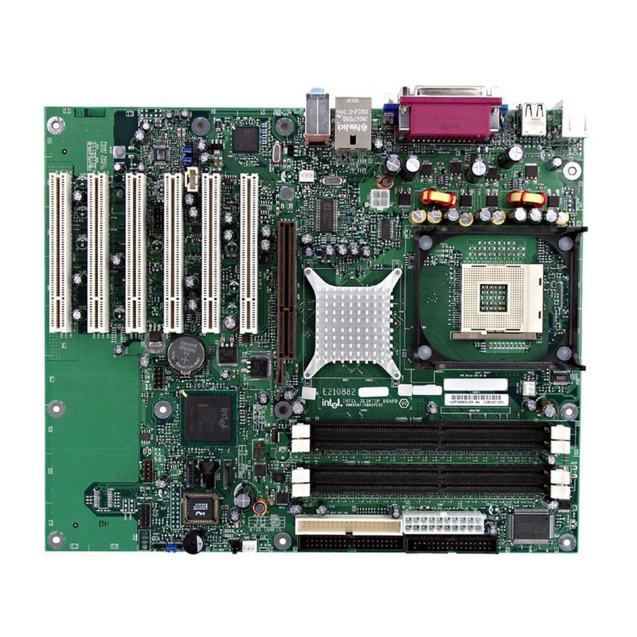
Intel Desktop Boards D865GBF/D865GLC Product Guide Desktop Board Components Figure 1 shows the approximate location of the major components on Desktop Board D865GBF. Line USB 2.0 USB 2.0 Devices Devices OM15224 Figure 1. Desktop Board D865GBF Components NOTE Desktop board D865GLC has three PCI bus add-in card connectors. -
Page 15: Desktop Board Components
USB 2.0 header Intel 82801EB (ICH5) USB 2.0 header Battery PCI bus add-in card connectors Related Links: Go to the following links for the latest information about: • Intel Desktop Board D865GBF/D865GLC, http://www.intel.com/design/motherbd • processors, http://support.intel.com/support/motherboards/desktop • audio software and utilities, http://www.intel.com/design/motherbd •... -
Page 16: Processor
Desktop Board D865GBF/D865GLC requires an ATX12V compliant power supply to function according to desktop board specifications. The board has two ATX12V compliant power supply connectors that are needed to provide extra power to the Intel 865G chipset and Intel processor. Related Links: Go to the following link or sections in this manual for more information about: •... -
Page 17: Main Memory
Main Memory NOTE ® To be fully compliant with all applicable Intel SDRAM memory specifications, the board should be populated with DIMMs that support the Serial Presence Detect (SPD) data structure. If your memory modules do not support SPD, you will see a notification to this effect on the screen at power up. -
Page 18: Intel ® 865G Chipset
Intel ® 865G Chipset The Intel 865G chipset consists of the following devices: • Intel 82865G Graphics and Memory Controller Hub (GMCH) with AHA bus • Intel 82801EB I/O Controller Hub (ICH5) with AHA bus • Firmware Hub (FWH) Related Link: For more information about Intel 865G chipset, go to: http://developer.intel.com/design/nav/pcserver.htm... -
Page 19: Input/Output (I/O) Controller
Support for RJ-45 connector with status indicator LEDs • Programmable transit threshold • Configurable EEPROM that contains the MAC address LAN Subsystem Software For LAN software and drivers, refer to the D865GLC or D865GBF link on Intel’s World Wide Web site at: http://support.intel.com/support/motherboards/desktop... -
Page 20: Rj-45 Lan Connector Leds
Intel Desktop Boards D865GBF/D865GLC Product Guide RJ-45 LAN Connector LEDs Two LEDs are built into the RJ-45 LAN connector. Table 6 describes the LED states when the board is powered up and the 10/100 Ethernet LAN subsystem is operating. Table 6. -
Page 21: Enhanced Ide Interface
Accelerated Graphics Port (AGP) NOTE Desktop Board D865GBF/D865GLC is only compatible with 0.8 V and 1.5 V AGP cards. The AGP connector is keyed for 0.8 V and 1.5 V AGP cards only; the connector is not mechanically compatible with legacy 3.3 V AGP cards. Do not attempt to install a legacy 3.3 V AGP card. -
Page 22: Security Passwords
Intel Desktop Boards D865GBF/D865GLC Product Guide Security Passwords The BIOS includes security features that restrict whether the BIOS Setup program can be accessed and who can boot the computer. A supervisor password and a user password can be set for the Setup and for booting the computer, with the following restrictions: •... -
Page 23: Fan Connectors
Desktop Board Features Fan Connectors The desktop board has two chassis fan connectors (Intel Precision Cooling Technology) and one processor fan connector. See Figure 15 on page 44 for the location of the fan connectors. ® Fan Speed Control (Intel... -
Page 24: Resume On Ring
Intel Desktop Boards D865GBF/D865GLC Product Guide CR7J1 OM15225 Figure 2. Location of Standby Power Indicator CAUTION Power supplies used with this desktop board must be able to provide enough standby current to support the standard Instantly Available (ACPI S3 sleep state) configuration. If the standby current necessary to support multiple wake events from the PCI and/or USB buses exceeds power supply capacity, the desktop board may lose register settings stored in memory. -
Page 25: Wake From Ps/2 Keyboard/Mouse
Desktop Board Features Wake from PS/2 Keyboard/Mouse PS/2 keyboard/mouse activity wakes the computer from an ACPI S1 or S3 state. PME# Wakeup Support When the PME# signal on the PCI bus is asserted, the computer wakes from an ACPI S1, S3, or S5 state. - Page 26 Intel Desktop Boards D865GBF/D865GLC Product Guide...
-
Page 27: Installing And Replacing Desktop Board Components
2 Installing and Replacing Desktop Board Components This chapter tells you how to: • Install the I/O shield • Install and remove the desktop board • Install and remove a processor and memory • Install and remove an AGP card •... -
Page 28: Installation Precautions
Intel Desktop Boards D865GBF/D865GLC Product Guide Installation Precautions When you install and test the Intel desktop board, observe all warnings and cautions in the installation instructions. To avoid injury, be careful of: • Sharp pins on connectors • Sharp pins on printed circuit assemblies •... -
Page 29: Chassis And Component Certifications
Use Only for Intended Applications All Intel desktop boards are evaluated as Information Technology Equipment (I.T.E.) for use in personal computers for installation in homes, offices, schools, computer rooms, and similar locations. The suitability of this product for other applications or environments, such as medical, industrial, alarm systems, test equipment, etc. -
Page 30: Installing The I/O Shield
Intel Desktop Boards D865GBF/D865GLC Product Guide Installing the I/O Shield The desktop board comes with an I/O shield. When installed in the chassis, the shield blocks radio frequency transmissions, protects internal components from dust and foreign objects, and promotes correct airflow within the chassis. -
Page 31: Installing And Removing The Desktop Board
Refer to Appendix B for regulatory requirements. Refer to your chassis manual for instructions on installing and removing the desktop board. Figure 4 shows the location of the 11 mounting holes for Desktop Board D865GBF. Desktop Board D865GLC has eight mounting holes. -
Page 32: Installing And Removing A Processor
Desktop Board D865GBF/D865GLC has an integrated processor fan heat sink retention mechanism (RM). For instructions on how to install the processor fan heat sink to the integrated processor fan heat sink RM, refer to the boxed processor manual or the Intel World Wide Web site at: http://support.intel.com/support/processors/pentium4/intnotes478.htm... -
Page 33: Connecting The Processor Fan Heat Sink Cable
Figure 6. Connecting the Processor Fan Heat Sink Cable to the Processor Fan Connector Removing the Processor For instruction on how to remove the processor fan heat sink and processor, refer to the processor installation manual or the Intel World Wide Web site at: http://support.intel.com/support/processors/pentium4/intnotes478.htm... -
Page 34: Installing And Removing Memory
Intel Desktop Boards D865GBF/D865GLC Product Guide Installing and Removing Memory CAUTION To be fully compliant with all applicable Intel SDRAM memory specifications, the boards require DIMMs that support the Serial Presence Detect (SPD) data structure. You can access the PC Serial Presence Detect Specification at: http://www.intel.com/technology/memory/pcsdram/spec/... -
Page 35: Installing Dimms
Installing and Replacing Desktop Board Components Installing DIMMs Before installing DIMMs, read and follow these guidelines for dual channel configuration. NOTE Performance Acceleration Technology (PAT) requires a processor with 800 MHz FSB frequency and DDR400 memory. Install a matched pair of DIMMs equal in speed, size, and technology (see Figure 8) in DIMM 0 in both channels A and B. -
Page 36: Removing Dimms
Intel Desktop Boards D865GBF/D865GLC Product Guide CAUTION Install memory in the DIMM sockets prior to installing an AGP video card to avoid interference with the memory retention mechanism. To install DIMMs, follow these steps: 1. Observe the precautions in “Before You Begin” on page 27. -
Page 37: Installing And Removing An Agp Card
Installing and Replacing Desktop Board Components Installing and Removing an AGP Card CAUTION When installing any AGP card in the desktop board, ensure that it is fully seated in the AGP connector before you power on the system. If the card is not fully seated in the AGP connector, an electrical short may result across the AGP connector pins. -
Page 38: Connecting The Ide Cable
Observe the precautions in “Before You Begin” on page 27. • Attach the cable end with the single connector to the Intel desktop board (A). • Attach the cable end with the two closely spaced connectors to the drives (B). -
Page 39: Connecting The Serial Ata Cable
Installing and Replacing Desktop Board Components Connecting the Serial ATA Cable The SATA cable (4-conductor) supports the Serial ATA protocol and connects a single drive to the desktop board. Either end of the cable can be connected to the SATA drive or the connector on the board (see Figure 12). -
Page 40: Connecting Internal Headers
Intel Desktop Boards D865GBF/D865GLC Product Guide Connecting Internal Headers Figure 13 shows the location of internal headers. J9A2 J9F1 J9H1 J9J1 OM15240 Item Description Front panel audio USB 2.0 USB 2.0 Front panel Power LED Figure 13. Internal Headers... -
Page 41: Installing A Front Panel Audio Solution
Installing and Replacing Desktop Board Components Installing a Front Panel Audio Solution Figure 13-A shows the location of the front panel audio header. Table 8 shows the pin assignments for the front panel audio header. Table 8. Front Panel Audio Header Signal Names (J9A2) Signal Name Signal Name AUD-MIC... -
Page 42: Setting Up The Flexible 6-Channel Audio With Jack Sensing
Intel Desktop Boards D865GBF/D865GLC Product Guide Setting up the Flexible 6-Channel Audio with Jack Sensing After installing the SoundMAX 4 XL audio driver from the Intel Express Installer CD-ROM, the multi-channel audio feature can now be enabled. See Figure 14 for back panel audio connectors. -
Page 43: Connecting Usb 2.0 Headers
Installing and Replacing Desktop Board Components Connecting USB 2.0 Headers Before connecting USB 2.0 headers, observe the precautions in “Before You Begin” on page 27. Figure 13-A and -B on page 40 shows the location of the USB 2.0 headers. Table 9 shows the pin assignments for the headers. -
Page 44: Connecting Hardware Control And Power Cables
Intel Desktop Boards D865GBF/D865GLC Product Guide Connecting Hardware Control and Power Cables Figure 15 shows the location of the chassis intrusion and fan headers, and power connectors. Chassis rear fan J6B1 12 V processor core voltage connector Processor J6B1 Chassis intrusion... -
Page 45: Connecting The Chassis Intrusion Cable
Installing and Replacing Desktop Board Components Connecting the Chassis Intrusion Cable Connect the chassis intrusion cable to the header shown in Figure 15. Connecting Fans Connect the processor’s fan heat sink cable to the processor fan header on the board. Connect chassis fan cables to the board fan headers. -
Page 46: Setting The Bios Configuration Jumper Block
Intel Desktop Boards D865GBF/D865GLC Product Guide Setting the BIOS Configuration Jumper Block CAUTION Always turn off the power and unplug the power cord from the computer before changing the jumper. Moving the jumper with the power on may result in unreliable computer operation. -
Page 47: Clearing Passwords
Installing and Replacing Desktop Board Components Clearing Passwords This procedure assumes that the board is installed in the computer and the configuration jumper block is set to normal mode. 1. Observe the precautions in “Before You Begin” on page 27. 2. -
Page 48: Replacing The Battery
Intel Desktop Boards D865GBF/D865GLC Product Guide Replacing the Battery A coin-cell battery (CR2032) powers the real-time clock and CMOS memory. When the computer is not plugged into a wall socket, the battery has an estimated life of three years. When the computer is plugged in, the standby current from the power supply extends the life of the battery. - Page 49 Installing and Replacing Desktop Board Components Esiste il pericolo di un esplosione se la pila non viene sostituita in modo corretto. Utilizzare solo pile uguali o di tipo equivalente a quelle consigliate dal produttore. Per disfarsi delle pile usate, seguire le istruzioni del produttore. Existe peligro de explosión si la pila no se cambia de forma adecuada.
- Page 50 Intel Desktop Boards D865GBF/D865GLC Product Guide Risiko letupan wujud jika bateri digantikan dengan jenis yang tidak betul. Bateri sepatutnya dikitar semula jika boleh. Pelupusan bateri terpakai mestilah mematuhi peraturan alam sekitar tempatan. Risc de explo v súlade s ostredia. okoljevarstvenimi predpisi.
-
Page 51: Removing The Battery
Installing and Replacing Desktop Board Components To replace the battery, follow these steps: 1. Observe the precautions in “Before You Begin” (see page 27). 2. Turn off all peripheral devices connected to the computer. Disconnect the computer’s power cord from the AC power source (wall outlet or power adapter). 3. - Page 52 Intel Desktop Boards D865GBF/D865GLC Product Guide...
-
Page 53: Updating The Bios
Updating the BIOS with the Intel Express BIOS Update Utility With the Intel Express BIOS Update utility you can update the system BIOS while in the Windows environment. The BIOS file is included in an automated update utility that combines the ®... -
Page 54: Updating The Bios With The Iflash Memory Update Utility
• Iflash Memory Update utility You can obtain the BIOS update file through your computer supplier or by navigating to the Desktop Board D865GBF or D865GLC page on the Intel World Wide Web site: http://support.intel.com/support/motherboards/desktop NOTE Review the instructions distributed with the update utility before attempting a BIOS update. -
Page 55: Recovering The Bios
Updating the BIOS Recovering the BIOS It is unlikely that anything will interrupt the BIOS update; however, if an interruption occurs, the BIOS could be damaged. The following steps explain how to recover the BIOS if an update fails. The following procedure uses recovery mode for the Setup program. See page 46 for more information on Setup modes. - Page 56 Intel Desktop Boards D865GBF/D865GLC Product Guide...
-
Page 57: Using The Bios Setup Program
Service (BIS)* hardware features features management power supply changes to set credentials, and components available features controls program options configures extended through the configuration chipset memory settings * For information about the BIS, refer to the Intel Web site at: http://developer.intel.com/design/security/index1.htm... -
Page 58: Maintenance Menu
Clears the Wired for Management Boot Integrity Service • Cancel (BIS) credentials. CPU Stepping Signature No options Displays processor’s Stepping Signature. CPU Microcode Update Revision No options Displays processor’s Microcode Update Revision. * For information about the BIS, refer to the Intel Web site at: http://developer.intel.com/design/security/index1.htm... -
Page 59: Main Menu
Using the BIOS Setup Program Main Menu Main Advanced Security Power Boot Exit BIOS Version xxxxx10A.86A.xxxx.xxx Processor Type Intel(R) Pentium(R) 4 Hyper-Threading Technology [Enabled] Processor Speed X.XX GHz System Bus Speed XXX MHz System Memory Speed XXX MHz Cache RAM XXX KB... -
Page 60: Advanced Menu
Intel Desktop Boards D865GBF/D865GLC Product Guide Advanced Menu Main Advanced Security Power Boot Exit Setup Warning: Setting items on this screen to incorrect values may cause your system to malfunction! ` PCI Configuration ` Boot Configuration ` Peripheral Configuration ` IDE Configuration... -
Page 61: Pci Configuration Submenu
Using the BIOS Setup Program PCI Configuration Submenu Main Advanced Security Power Boot Exit PCI Configuration PCI Slot 1 IRQ Priority [Auto] PCI Slot 2 IRQ Priority PCI Slot 3 IRQ Priority PCI Slot 4 IRQ Priority PCI Slot 5 IRQ Priority Select Screen Select Item Select ` Sub-Menu... -
Page 62: Boot Configuration Submenu
Intel Desktop Boards D865GBF/D865GLC Product Guide Boot Configuration Submenu Main Advanced Security Power Boot Exit Boot Configuration Plug & Play O/S [No] Numlock [On] Select Screen Select Item Select ` Sub-Menu Enter General Help Setup Defaults Save and Exit Exit The submenu shown in Table 18 is used to set the Plug &... -
Page 63: Peripheral Configuration Submenu
Using the BIOS Setup Program Peripheral Configuration Submenu Main Advanced Security Power Boot Exit Peripheral Configuration Serial Port A [Auto] Parallel Port [Auto] Mode [Bi-directional] LAN Device [Enabled] Audio [Enabled] Select Screen Select Item Select ` Sub-Menu Enter General Help Setup Defaults Save and Exit Exit... - Page 64 Intel Desktop Boards D865GBF/D865GLC Product Guide Table 19. Peripheral Configuration Submenu (continued) Feature Options Description • Output only Mode Selects the mode for the parallel port. Not available if the parallel port is disabled. • Bi-directional (default) Output Only operates in AT*-compatible mode.
-
Page 65: Ata/Ide Configuration Submenu
Using the BIOS Setup Program ATA/IDE Configuration Submenu Main Advanced Security Power Boot Exit IDE Configuration ATA/IDE Configuration [Legacy] Legacy IDE Channels [PATA Pri and Sec] PCI IDE Bus Master [Enabled] Hard Disk Pre-Delay [Disabled] ` [PATA Primary Master xxxxxxx] ` [PATA Primary Slave Not Detected] ` [PATA Secondary Master :... -
Page 66: Pata And Sata Submenus
Intel Desktop Boards D865GBF/D865GLC Product Guide PATA and SATA Submenus Main Advanced Security Power Boot Exit ` [SATA Port-0 Xxxxxxxx Type [Auto] Maximum Capacity [Auto] Configuration Options Selected by BIOS LBA Mode [Supported] Block Mode: 16 sectors PIO Mode Mode 4... - Page 67 Using the BIOS Setup Program Table 21. SATA and PATA Submenus (continued) Feature Options Description • Auto (default) DMA Mode Specifies the Ultra DMA mode for the drive. • SWDMA 0 • SWDMA 1 • SWDMA 2 • MWDMA 0 •...
-
Page 68: Diskette Configuration Submenu
Intel Desktop Boards D865GBF/D865GLC Product Guide Diskette Configuration Submenu Main Advanced Security Power Boot Exit Diskette Configuration Diskette Controller [Enabled] Floppy A [1.44/1.25MB 3½"] Diskette Write Protect [Disabled] Select Screen Select Item Select ` Sub-Menu Enter General Help Setup Defaults... -
Page 69: Event Log Configuration Submenu
Using the BIOS Setup Program Event Log Configuration Submenu Main Advanced Security Power Boot Exit Event Log Configuration Event Log [Space Available] View Event Log Clear Event Log Event Logging [Enabled] ECC Event Logging [Enabled] Mark Events As Read Select Screen Select Item Select ` Sub-Menu Enter... -
Page 70: Video Configuration Submenu
Intel Desktop Boards D865GBF/D865GLC Product Guide Video Configuration Submenu Main Advanced Security Power Boot Exit Video Configuration AGP Aperture Size [ 64MB] Primary Video Adapter [AGP] Frame Buffer Size [1MB] Select Screen Select Item Select ` Sub- Enter Menu General Help... -
Page 71: Usb Configuration Submenu
Using the BIOS Setup Program USB Configuration Submenu Main Advanced Security Power Boot Exit USB Configuration High-Speed USB [Enabled] Legacy USB Support [Enabled] Select Screen Select Item Select ` Sub-Menu Enter General Help Setup Defaults Save and Exit Exit The submenu shown in Table 25 is used to configure USB features. Table 25. -
Page 72: Chipset Configuration Submenu
Intel Desktop Boards D865GBF/D865GLC Product Guide Chipset Configuration Submenu Main Advanced Security Power Boot Exit Chipset Configuration Setup Warning: Setting items on this screen to incorrect values may cause your system to malfunction! ISA Enable Bit [Enabled] PCI Latency Timer... - Page 73 Using the BIOS Setup Program Table 25. Chipset Configuration Submenu (continued) Feature Options Description • Default (default) Extended Configuration Chooses the default or user defined settings for the extended configuration options. • User Defined Graphics Core Frequency • Auto (default) Allows override of detected graphics core frequency value.
-
Page 74: Fan Control Submenu
Intel Desktop Boards D865GBF/D865GLC Product Guide Fan Control Submenu Main Advanced Security Power Boot Exit Fan Control Configuration Setup Warning: These options will not take effect until power has been completely removed from the system. After saving the BIOS settings and turning the system... -
Page 75: Hardware Monitoring Submenu
Using the BIOS Setup Program Hardware Monitoring Submenu Main Advanced Security Power Boot Exit Hardware Monitoring Note: These measurements are approximate and should not be used for validation purposes. Processor Zone Temperature C/111 System Zone 1 Temperature C/98 System Zone 2 Temperature C/95 Processor Fan Speed 2394 RPM... -
Page 76: Security Menu
Intel Desktop Boards D865GBF/D865GLC Product Guide Security Menu Main Advanced Security Power Boot Exit Supervisor Password Not Installed User Password Not Installed Set Supervisor Password Set User Password Chassis Intrusion [Disabled] Select Screen Select Item Select ` Sub-Menu Enter General Help... -
Page 77: Power Menu
Using the BIOS Setup Program Power Menu Main Advanced Security Power Boot Exit ` ACPI After Power Failure [Last State] The options below are not related to ACPI and may be ignored when shutting down using an ACPI OS. Wake on PCI PME [Stay Off] Select Screen Select Item... -
Page 78: Acpi Submenu
Intel Desktop Boards D865GBF/D865GLC Product Guide ACPI Submenu Main Advanced Security Power Boot Exit Advanced Configuration and Power Interface S1 is the safest mode but consumes more power. ACPI Suspend State [S1 State] S3 consumes low power Wake on LAN from S5... -
Page 79: Boot Menu
Using the BIOS Setup Program Boot Menu Main Advanced Security Power Boot Exit Silent BOOT [Enabled] Intel ® Rapid BIOS Boot [Enabled] Scan User Flash Area [Enabled] PXE Boot to LAN [Disabled] USB Boot [Enabled] ` Boot Device Priority ` Hard Disk Drives... -
Page 80: Boot Device Priority Submenu
Intel Desktop Boards D865GBF/D865GLC Product Guide Boot Device Priority Submenu Main Advanced Security Power Boot Exit Specifies the boot Boot Device FLOPPY DRIVE] sequence from the Boot Device [xxxxxxxxxxx] available devices. Boot Device [xxxxxxxxxxx] A device enclosed in parenthesis has been... -
Page 81: Hard Disk Drives Submenu
Using the BIOS Setup Program Hard Disk Drives Submenu Main Advanced Security Power Boot Exit Specifies the boot Drive [xxxxxxxxxxxxx] sequence from the Drive [xxxxxxxxxxxxx] available devices. Drive [xxxxxxxxxxxxx] Select the boot device Drive [xxxxxxxxxxxxx] with UpArrow or DownArrow key. Press Enter to set the selections as the... -
Page 82: Removable Devices Submenu
Intel Desktop Boards D865GBF/D865GLC Product Guide Removable Devices Submenu Main Advanced Security Power Boot Exit Specifies the boot Drive FLOPPY DRIVE] sequence from the available devices. Select the boot device with UpArrow or DownArrow key. Press Enter to set the selections as the intended boot device. -
Page 83: Atapi Cd-Rom Drives
Using the BIOS Setup Program ATAPI CD-ROM Drives Main Advanced Security Power Boot Exit Specifies the boot 1st Drive [xxxxxxx] sequence from the Drive [xxxxxxx] available devices. Select the boot device with UpArrow or DownArrow key. Press Enter to set the selections as the intended boot device. -
Page 84: Exit Menu
Intel Desktop Boards D865GBF/D865GLC Product Guide Exit Menu Main Advanced Security Power Boot Exit Exit Saving Changes Exit Discarding Changes Load Optimal Defaults Load Custom Defaults Save Custom Defaults Discard Changes Select Screen Select Item Select ` Sub-Menu Enter General Help... -
Page 85: Technical Reference
5 Technical Reference Board Connectors This chapter shows the location of the: • Back panel connectors • Audio connectors • Add-in board and peripheral interface connectors CAUTION Many of the midboard and front panel connectors provide operating voltage (+5 V dc and +12 V dc, for example) to devices inside the computer chassis, such as fans and internal peripherals. -
Page 86: Back Panel Connectors
Intel Desktop Boards D865GBF/D865GLC Product Guide Back Panel Connectors NOTE The line out connector, located on the back panel, is designed to power either headphones or amplified speakers only. Poor audio quality may occur if passive (non-amplified) speakers are connected to this output. -
Page 87: Audio Connectors
Technical Reference Audio Connectors Figure 13 shows the approximate location of the audio connectors. J9C1 J9A2 J8B1 OM15236 Item Description CD-ROM (ATAPI-style) Front panel audio Auxiliary line in (ATAPI-style) Figure 19. Audio Connectors... -
Page 88: Add-In Card And Peripheral Interface Connectors
Intel Desktop Boards D865GBF/D865GLC Product Guide Add-In Card and Peripheral Interface Connectors Figure 20 shows the PCI bus add-in card and peripheral interface connectors for Desktop Board D865GBF. Desktop Board D865GLC has three PCI bus add-in card connectors. OM15238 OM15238... -
Page 89: Desktop Board Resources
Technical Reference Desktop Board Resources Memory Map Table 38. System Memory Map Address Range (decimal) Address Range (hex) Size Description 1024 K - 4194304 K 100000 - FFFFFFFF 4095 MB Extended Memory 960 K - 1024 K F0000 - FFFFF 64 KB Runtime BIOS 896 K - 960 K... -
Page 90: Interrupts
Intel Desktop Boards D865GBF/D865GLC Product Guide Interrupts Table 40. Interrupts System Resource I/O channel check Reserved, interval timer Reserved, keyboard buffer full Reserved, cascade interrupt from slave PIC COM2* COM1* LPT2 (Plug and Play option) ** Floppy drive controller LPT1*... -
Page 91: A Error Messages And Indicators
A Error Messages and Indicators Desktop Board D865GBF/D865GLC reports POST errors in two ways: • By sounding a beep code • By displaying an error message on the monitor BIOS Beep Codes The BIOS beep codes are listed in Table 41. The BIOS also issues a beep code (one long tone followed by two short tones) during POST if the video configuration fails (a faulty video card or no card installed) or if an external ROM module does not properly checksum to zero. -
Page 92: Bios Error Messages
Intel Desktop Boards D865GBZ/D865GLC Product Guide BIOS Error Messages When a recoverable error occurs during the POST, the BIOS displays an error message describing the problem. Table 42. BIOS Error Messages Error Message Explanation GA20 Error An error occurred with Gate-A20 when switching to protected mode during the memory test. - Page 93 Error Messages and Indicators Table 42. BIOS Error Messages (continued) Error Message Explanation Memory Size Decreased Memory size has decreased since the last boot. If no memory was removed, then memory may be bad. Memory Size Increased Memory size has increased since the last boot. If no memory was added, there may be a problem with the system.
- Page 94 Intel Desktop Boards D865GBZ/D865GLC Product Guide...
-
Page 95: B Regulatory Compliance
This appendix contains safety standards, electromagnetic compatibility (EMC) regulations, and product certification markings for Desktop Board D865GBF/D865GLC. Safety Regulations Desktop Board D865GBF/D865GLC complies with the safety regulations stated in Table 43 when correctly installed in a compatible host system. Table 43. -
Page 96: Product Certification Markings
Desktop Board D865GBF/D865GLC has the following product certification markings: • UL joint US/Canada Recognized Component mark: consists of small c followed by a stylized backward UR and followed by a small US. Includes adjacent UL file number for Intel desktop boards: E210882 (component side). •... - Page 97 Regulatory Compliance • Korean Class B statement translated as follows: this is household equipment that is certified to comply with EMC requirements. You may use this equipment in residential environments and other non-residential environments.
- Page 98 Intel Desktop Boards D865GBZ/D865GLC Product Guide...