Cisco AIR-BR1310G-A-K9 - Aironet 1310 Outdoor Access Point/Bridge Hardware Installation Manual
Wireless outdoor access point/bridge
Hide thumbs
Also See for AIR-BR1310G-A-K9 - Aironet 1310 Outdoor Access Point/Bridge:
- Datasheet (15 pages) ,
- Hardware installation manual (146 pages)
Table of Contents
Advertisement
Quick Links
Cisco Aironet 1300 Series Wireless
Outdoor Access Point/Bridge
Hardware Installation Guide
December 2006
Corporate Headquarters
Cisco Systems, Inc.
170 West Tasman Drive
San Jose, CA 95134-1706
USA
http://www.cisco.com
Tel: 408 526-4000
800 553-NETS (6387)
Fax: 408 526-4100
Text Part Number: OL-5048-06
Advertisement
Table of Contents

Related Manuals for Cisco AIR-BR1310G-A-K9 - Aironet 1310 Outdoor Access Point/Bridge


Summary of Contents for Cisco AIR-BR1310G-A-K9 - Aironet 1310 Outdoor Access Point/Bridge
- Page 1 Cisco Aironet 1300 Series Wireless Outdoor Access Point/Bridge Hardware Installation Guide December 2006 Corporate Headquarters Cisco Systems, Inc. 170 West Tasman Drive San Jose, CA 95134-1706 http://www.cisco.com Tel: 408 526-4000 800 553-NETS (6387) Fax: 408 526-4100 Text Part Number: OL-5048-06...
- Page 2 OR ITS SUPPLIERS HAVE BEEN ADVISED OF THE POSSIBILITY OF SUCH DAMAGES. CCVP, the Cisco Logo, and the Cisco Square Bridge logo are trademarks of Cisco Systems, Inc.; Changing the Way We Work, Live, Play, and Learn is a service mark of Cisco Systems, Inc.;...
-
Page 3: Table Of Contents
C H A P T E R Product Terminology Autonomous Access Point/Bridge Lightweight Access Point Guidelines for Using a Lightweight Access Point/Bridge Key Features Power Integrated Antenna External Antenna Ethernet Ports Enclosure Connectors LEDs Cisco Aironet 1300 Series Wireless Outdoor Access Point/Bridge Hardware Installation Guide OL-5048-06... - Page 4 Mounting the Access Point/Bridge Mounting Hardware Window Mounting Multi-Function Mount Access Point Bracket Mast Bracket LEDs Autonomous Access Point/Bridge Aligning the Autonomous Bridge Antenna Using RSSI LED Indications Cisco Aironet 1300 Series Wireless Outdoor Access Point/Bridge Hardware Installation Guide OL-5048-06...
- Page 5 Clearing Manually Entered Controller Information Manually Resetting the Access Point to Defaults Returning the Access Point to Autonomous Mode Using a Controller to Return the Access Point to Autonomous Mode Cisco Aironet 1300 Series Wireless Outdoor Access Point/Bridge Hardware Installation Guide OL-5048-06...
- Page 6 European Community, Switzerland, Norway, Iceland, and Liechtenstein Declaration of Conformity with Regard to the R&TTE Directive 1999/5/EC Declaration of Conformity for RF Exposure Guidelines for Operating Cisco Aironet Access Points and Bridges in Japan Japanese Translation English Translation Administrative Rules for Cisco Aironet Access Points and Bridges in Taiwan...
- Page 7 Contents Load-Dump Protection for Transportation Vehicles A P P E N D I X Load-Dump Protection L O S S A R Y N D E X Cisco Aironet 1300 Series Wireless Outdoor Access Point/Bridge Hardware Installation Guide OL-5048-06...
- Page 8 Contents Cisco Aironet 1300 Series Wireless Outdoor Access Point/Bridge Hardware Installation Guide viii OL-5048-06...
-
Page 9: Preface
Preface Audience This guide is for the networking professional who installs and manages the Cisco Aironet 1300 Series Outdoor Access Point/Bridge. The 1300 series access point/bridge is available in autonomous and lightweight configurations. To use this guide with an autonomous access point/bridge, you should have experience working with Cisco IOS software and be familiar with the concepts and terminology of wireless local area networks. -
Page 10: Conventions
Means reader take note. Notes contain helpful suggestions or references to materials not contained in Note this manual. Means reader be careful. In this situation, you might do something that could result in equipment Caution damage or loss of data. Cisco Aironet 1300 Series Wireless Outdoor Access Point/Bridge Hardware Installation Guide OL-5048-06... - Page 11 (Para ver as traduções dos avisos que constam desta publicação, consulte o apêndice “Translated Safety Warnings” - “Traduções dos Avisos de Segurança”). Cisco Aironet 1300 Series Wireless Outdoor Access Point/Bridge Hardware Installation Guide OL-5048-06...
-
Page 12: Related Publications
Click this link to browse to the Cisco Wireless documentation home page: http://www.cisco.com/en/US/products/hw/wireless/tsd_products_support_category_home.html To browse to the 1300 series access point documentation, click Cisco Aironet 1300 Series listed under “Wireless LAN Access.” To browse to controller documentation, click Cisco 4400 Series Wireless LAN Controllers or Cisco 2000 Series Wireless LAN Controllers listed under “Wireless LAN Controllers.”... -
Page 13: Product Documentation Dvd
Store at this URL: http://www.cisco.com/go/marketplace/docstore Ordering Documentation You must be a registered Cisco.com user to access Cisco Marketplace. Registered users may order Cisco documentation at the Product Documentation Store at this URL: http://www.cisco.com/go/marketplace/docstore If you do not have a user ID or password, you can register at this URL: http://tools.cisco.com/RPF/register/register.do... -
Page 14: Reporting Security Problems In Cisco Products
We encourage you to use Pretty Good Privacy (PGP) or a compatible product (for example, GnuPG) to encrypt any sensitive information that you send to Cisco. PSIRT can work with information that has been encrypted with PGP versions 2.x through 9.x. -
Page 15: Obtaining Technical Assistance
URL: http://www.cisco.com/en/US/support/index.html Access to all tools on the Cisco Support website requires a Cisco.com user ID and password. If you have a valid service contract but do not have a user ID or password, you can register at this URL: http://tools.cisco.com/RPF/register/register.do... -
Page 16: Locating The Product Serial Number
The access point/bridge serial number is located on the bottom of the cabinet (refer to Figure Figure 1 Location of Access Point Serial Number Label SN: AAANNNNXXXX SN: AAANNNNXXXX Cisco Aironet 1300 Series Wireless Outdoor Access Point/Bridge Hardware Installation Guide OL-5048-06... -
Page 17: Submitting A Service Request
Cisco engineer. The TAC Service Request Tool is located at this URL: http://www.cisco.com/techsupport/servicerequest For S1 or S2 service requests, or if you do not have Internet access, contact the Cisco TAC by telephone. (S1 or S2 service requests are those in which your production network is down or severely degraded.) Cisco engineers are assigned immediately to S1 and S2 service requests to help keep your business operations running smoothly. -
Page 18: Definitions Of Service Request Severity
• The Cisco Online Subscription Center is the website where you can sign up for a variety of Cisco e-mail newsletters and other communications. Create a profile and then select the subscriptions that you would like to receive. To visit the Cisco Online Subscription Center, go to this URL: http://www.cisco.com/offer/subscribe... - Page 19 Preface Obtaining Additional Publications and Information Networking products offered by Cisco, as well as customer support services, can be obtained at • this URL: http://www.cisco.com/en/US/products/index.html • Networking Professionals Connection is an interactive website where networking professionals share questions, suggestions, and information about networking products and technologies with Cisco experts and other networking professionals.
- Page 20 Preface Obtaining Additional Publications and Information Cisco Aironet 1300 Series Wireless Outdoor Access Point/Bridge Hardware Installation Guide OL-5048-06...
-
Page 21: Chapter 1 Overview
C H A P T E R Overview The Cisco Aironet 1300 Series Outdoor Access Point/Bridge is available in autonomous and lightweight products. The autonomous product can support standalone network configurations with all configuration settings maintained within the unit. The autonomous product can be configured for multiple operating roles such as, access point, bridge, and workgroup bridge. -
Page 22: Lightweight Access Point
The lightweight access points contain one integrated radio: a 2.4-GHz radio (IEEE 802.11g). Using a controller, you can configure the radio settings. In the Cisco Centralized Wireless LAN architecture, access points operate in the lightweight mode (as opposed to autonomous mode). The lightweight access points associate to a controller. The controller manages the configuration, firmware, and controls transactions such as 802.1x authentication. -
Page 23: Key Features
• The autonomous access point/bridge supports these additional key features: Receive Signal Strength Indicator (RSSI) LED patterns for easy antenna alignment • Control using Cisco IOS commands, Internet browser, SNMP, or serial interface • Operating modes: • Root and non-root bridge –... -
Page 24: Power
Power The access point/bridge receives inline power from the Cisco Aironet Power Injector (hereafter called the power injector). Dual-coax cables are used to provide Ethernet data and power from the power injector to the access point/bridge. The power injector is an external unit designed for operation in a sheltered environment, such as inside a building or vehicle. -
Page 25: Integrated Antenna
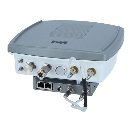
Figure 1-1) for use with Cisco Aironet 2.4-GHz antennas. Two reverse-TNC type RF connectors are provided on the end of the unit to support single or diversity antenna configurations. The antennas connect to the access point/bridge antenna connectors using a coax cable. -
Page 26: Ethernet Ports
Ground lug mounting screws Mounting posts Left antenna connector (external antenna LEDs access point/bridge configuration only) Primary right antenna connector (external Dual-coax Ethernet ports (F-Type connectors) antenna access point/bridge configuration only) Cisco Aironet 1300 Series Wireless Outdoor Access Point/Bridge Hardware Installation Guide OL-5048-06... -
Page 27: Leds
For additional information on the LEDs, refer to the “Checking the LEDs on an Autonomous Access Point/Bridge” section on page 4-2 or the “Checking the LEDs on Lightweight Access Points” section on page 5-2. Cisco Aironet 1300 Series Wireless Outdoor Access Point/Bridge Hardware Installation Guide OL-5048-06... -
Page 28: Operating Roles For The Autonomous Access Point/Bridge
Non-Root Bridge—Specifies that the unit is operating as a non-root bridge, that it connects to a • remote LAN network, and that it must associate with a Cisco Aironet root bridge using the wireless interface. •... -
Page 29: Network Examples With Autonomous Access Point/Bridges
LAN. The data is sent through the route that provides the best performance for the client. Figure 1-4 shows an autonomous access point acting as a repeater. Consult the Cisco IOS Software Configuration Guide for Access Points for instructions on setting up an access point as a repeater. -
Page 30: Root Access Point On A Wired Lan
Figure 1-5 shows access points acting as root units on a wired LAN. Figure 1-5 Access Points as Root Units on a Wired LAN Access point Access point Cisco Aironet 1300 Series Wireless Outdoor Access Point/Bridge Hardware Installation Guide 1-10 OL-5048-06... -
Page 31: Central Unit In An All-Wireless Network
LAN (see Figure 1-7). The bridge units can also support wireless clients. Figure 1-7 Root Bridge and Non-Root Bridge with Clients Root bridge Non-root bridge Cisco Aironet 1300 Series Wireless Outdoor Access Point/Bridge Hardware Installation Guide 1-11 OL-5048-06... -
Page 32: Point-To-Point Bridge Configuration
(see Figure 1-10). Figure 1-9 Workgroup Bridge Communicating with an Access Point Access point Workgroup bridge Figure 1-10 Workgroup Bridge Communicating with a Bridge Bridge Workgroup bridge Cisco Aironet 1300 Series Wireless Outdoor Access Point/Bridge Hardware Installation Guide 1-12 OL-5048-06... -
Page 33: Network Examples With Lightweight Access Points
Layer 3 configurations use IP addresses and UDP packets, which can be routed through large networks. Layer 3 operation is scalable and recommended by Cisco. This section illustrates a typical wireless network configuration containing lightweight access points and... - Page 34 Chapter 1 Overview Network Examples with Lightweight Access Points Cisco Aironet 1300 Series Wireless Outdoor Access Point/Bridge Hardware Installation Guide 1-14 OL-5048-06...
-
Page 35: Installation Overview
Safety Warnings, page 2-2 • Safety Information, page 2-3 • Unpacking the Access Point/Bridge, page 2-6 • • Before Beginning the Installation, page 2-7 Installation Summary, page 2-9 • Cisco Aironet 1300 Series Wireless Outdoor Access Point/Bridge Hardware Installation Guide OL-5048-06... -
Page 36: Safety Warnings
Safety Warnings Safety Warnings Translated versions of all safety warnings are available in the safety warning document that shipped with your access point or on Cisco.com. To browse to the document on Cisco.com, refer to Appendix A, “Translated Safety Warnings”... -
Page 37: Outdoor And Dc Power Source Installations
FCC-certified equipment. When used with approved Cisco Aironet antennas, Cisco Aironet products meet the uncontrolled environmental limits found in OET-65 and ANSI C95.1, 1991. Proper operation of this radio device according to the instructions in this publication results in user exposure substantially below the FCC recommended limits. - Page 38 Call your local power company. They will remove it safely. If an accident should occur with the power lines call for qualified emergency help immediately. Cisco Aironet 1300 Series Wireless Outdoor Access Point/Bridge Hardware Installation Guide OL-5048-06...
-
Page 39: Typical Outdoor Installation Components
Install the access point/bridge in an area where structures, trees, or hills do not obstruct radio signals • to and from the unit. Install the access point/bridge at a height sufficient to provide a clear line-of-sight signal path. • Cisco Aironet 1300 Series Wireless Outdoor Access Point/Bridge Hardware Installation Guide OL-5048-06... -
Page 40: Site Surveys
Power module and AC power cord • Quick start guide • Mounting instructions document • Read Me document • Translated safety warnings document • Cisco product registration and Cisco documentation feedback cards • Cisco Aironet 1300 Series Wireless Outdoor Access Point/Bridge Hardware Installation Guide OL-5048-06... -
Page 41: Before Beginning The Installation
The network administration or other IT professional responsible for installing and configuring the unit is a suitable professional installer. Following installation, access to the unit should be password-protected by the network administrator to maintain regulatory compliance. Cisco Aironet 1300 Series Wireless Outdoor Access Point/Bridge Hardware Installation Guide OL-5048-06... - Page 42 Mounting lugs Figure 2-3 Power Injector Indicators and Connectors Dual-coax Ethernet ports (F-Type connectors) Ethernet LAN port (RJ-45 connector) Power LED Console serial port (RJ-45 connector) Power jack Cisco Aironet 1300 Series Wireless Outdoor Access Point/Bridge Hardware Installation Guide OL-5048-06...
-
Page 43: Installation Summary
During the installation of the access point/bridge, you will perform the following operations: Connect a user-supplied Category 5 Ethernet cable from your wired LAN network to the power • injector. Cisco Aironet 1300 Series Wireless Outdoor Access Point/Bridge Hardware Installation Guide OL-5048-06... - Page 44 • Seal all external connectors with special weather sealing material. Configure security and other access point/bridge options. For additional information, refer to the Cisco IOS Software Configuration Guide for Access Points or the Cisco Wireless LAN Controller Configuration Guide.
-
Page 45: Chapter 3 Mounting Overview
This chapter provides an access point/bridge mounting overview. The following sections are included in this chapter: Mounting the Access Point/Bridge, page 3-2 • Mounting Hardware, page 3-2 • LEDs, page 3-5 • Cisco Aironet 1300 Series Wireless Outdoor Access Point/Bridge Hardware Installation Guide OL-5048-06... -
Page 46: Mounting The Access Point/Bridge
The wall mount kit (for indoor use) contains these items: • Wall mount bracket with 4 mounting bolts and washers – Two sub-mini RG-59 cables (12 in or 30.5 cm) – Cisco Aironet 1300 Series Wireless Outdoor Access Point/Bridge Hardware Installation Guide OL-5048-06... -
Page 47: Window Mounting
Connect the ground wire to the outdoor mounted access point/bridge using the supplied ground lug. Connect the power cable to the power injector. Tighten the nuts and bolts. Cisco Aironet 1300 Series Wireless Outdoor Access Point/Bridge Hardware Installation Guide OL-5048-06... -
Page 48: Access Point Bracket
The U-bolts provided with the roof mounting kit support mast diameters up to 1.75 in. (44.5 mm). For Note larger masts, you must supply the U-bolts to attach the access point/bridge. Cisco Aironet 1300 Series Wireless Outdoor Access Point/Bridge Hardware Installation Guide OL-5048-06... -
Page 49: Leds
SSID. To allow client associations, you must configure an SSID and enable the radio interface (refer to the Cisco IOS Software Configuration Guide for Access Points). -
Page 50: Aligning The Autonomous Bridge Antenna Using Rssi Led Indications
The RSSI LED indications are shown in Table 3-3). For the signal level (dBm), a smaller number represents a stronger signal because the signal level is given Note as a negative value. Cisco Aironet 1300 Series Wireless Outdoor Access Point/Bridge Hardware Installation Guide OL-5048-06... - Page 51 When using LEDs to maximize the signal, adjust the antenna until as many LEDs as possible are turned on and the rest are blinking as fast as possible. Cisco Aironet 1300 Series Wireless Outdoor Access Point/Bridge Hardware Installation Guide OL-5048-06...
- Page 52 Chapter 3 Mounting Overview LEDs Cisco Aironet 1300 Series Wireless Outdoor Access Point/Bridge Hardware Installation Guide OL-5048-06...
- Page 53 This chapter provides troubleshooting procedures for basic problems with the autonomous access point/bridge (model: AIR-BR1310G). For the most up-to-date, detailed troubleshooting information, refer to the Cisco Technical Support and Documentation website at the following URL: http://www.cisco.com/en/US/products/hw/wireless/tsd_products_support_category_home.html Sections in this chapter include: Checking the LEDs on an Autonomous Access Point/Bridge, page 4-2 •...
-
Page 54: Checking The Leds On An Autonomous Access Point/Bridge
Transmitting and receiving Ethernet errors. amber amber — — — Firmware error—disconnect and reconnect the power injector power jack. If the problem continues, contact technical support for assistance. Cisco Aironet 1300 Series Wireless Outdoor Access Point/Bridge Hardware Installation Guide OL-5048-06... - Page 55 LED flashing red to count out the first digit, then a short pause, followed by the LED flashing red to count out the second digit. Cisco Aironet 1300 Series Wireless Outdoor Access Point/Bridge Hardware Installation Guide OL-5048-06...
- Page 56 Radio not ready—contact technical support for assistance. Radio did not start—contact technical support for assistance. Radio failure—contact technical support for assistance. Radio did not flash its firmware—contact technical support for assistance. Cisco Aironet 1300 Series Wireless Outdoor Access Point/Bridge Hardware Installation Guide OL-5048-06...
-
Page 57: Power Injector
When power is applied to the access point/bridge, the unit activates the bootloader and begins the POST operations. The access point/bridge begins to load the Cisco IOS image when the POST operations are successfully completed. Upon successfully loading the image, the unit initializes and tests the radio. -
Page 58: Checking Power
SSID is tsunami for Root AP and Workgroup Bridge roles. • In Cisco IOS Release 12.3(4)JA or later, on initial power up the access point/bridge defaults to the Root AP role with the radio disabled and no default SSID configured. -
Page 59: Enabling The Radio Interface
Troubleshooting Autonomous Access Points and Bridges Checking Basic Configuration Settings In Cisco IOS Release 12.3(4)JA or later, you must create an SSID and enable the radio before the access Note point/bridge allows wireless associations from other devices. These changes to the default configuration improve the security of a newly installed access point/bridge. -
Page 60: Security Settings
LEAP, MAC address authentication, Message Integrity Check (MIC), WEP key hashing, and 802.1X protocol versions. If a Cisco Aironet non-root bridge or a non-root access point is unable to authenticate to your root bridge or root access point, verify that the security settings are the same as your access point/bridge settings. -
Page 61: Running The Ping Or Link Test
Open your web browser and enter the access point/bridge’s IP address in the browser address line. Press Step 1 Enter. An Enter Network Password window appears. Enter the administrator username and password. The default username is Cisco and the default password Step 2 is Cisco. The username and password are case sensitive. -
Page 62: Resetting The Autonomous Access Point/Bridge To The Default Configuration
Press Enter. Step 2 Enter the administrator username and password. The default username is Cisco and the default password is Cisco. The username and password are case sensitive. The Summary Status page appears. Click System Software and the System Software page appears. -
Page 63: Using The Cli On An Autonomous Access Point/Bridge
After the access point/bridge reboots, you can reconfigure the access point/bridge by using the Step 5 Web-browser interface or the CLI (refer to the Cisco IOS Software Configuration Guide for Access Points). The access point/bridge is configured with the factory default values including the IP address (set to receive an IP address using DHCP). -
Page 64: Browser Http Interface
Step 2 line. Press Enter. An Enter Network Password window appears. Enter the administrator username and password. The default username is Cisco and the default password Step 3 is Cisco. The username and password are case sensitive. The Summary Status page appears. -
Page 65: Obtaining The Autonomous Access Point/Bridge Image File
Step 9 After the access point/bridge reboots, you can reconfigure the access point/bridge by using the Web-browser interface or the CLI (refer to the Cisco IOS Software Configuration Guide for Access Points). For additional information click the Help icon on the Software Upgrade page. -
Page 66: Connecting To The Console Serial Port
Step 3 Step 4 At the prompts, enter the administrator username and password. The default username is Cisco and the default password is Cisco. The username and password are case sensitive. Cisco Aironet 1300 Series Wireless Outdoor Access Point/Bridge Hardware Installation Guide... -
Page 67: Obtaining The Tftp Server Software
Troubleshooting Autonomous Access Points and Bridges Obtaining the TFTP Server Software Obtaining the TFTP Server Software You can download TFTP server software from several web sites. Cisco recommends the shareware TFTP utility available at this URL: http://tftpd32.jounin.net Follow the instructions on the website for installing and using the utility. - Page 68 Chapter 4 Troubleshooting Autonomous Access Points and Bridges Obtaining the TFTP Server Software Cisco Aironet 1300 Series Wireless Outdoor Access Point/Bridge Hardware Installation Guide 4-16 OL-5048-06...
- Page 69 Troubleshooting Lightweight Access Points This chapter provides troubleshooting procedures for basic problems with the lightweight access point (model: LAP1310G). For the most up-to-date, detailed troubleshooting information, refer to the Cisco Technical Support and Documentation website at the following URL: http://www.cisco.com/en/US/products/hw/wireless/tsd_products_support_category_home.html...
-
Page 70: Checking The Leds On Lightweight Access Points
LEDs. Figure 5-1 LEDs Radio LED Ethernet LED Status LED Install LED The Install LED is not used on the 1300 series lightweight access points. Note Cisco Aironet 1300 Series Wireless Outdoor Access Point/Bridge Hardware Installation Guide OL-5048-06... -
Page 71: Led Indications
– Amber – Resetting the configuration options to factory defaults. reset Failure Firmware failure; try disconnecting and reconnecting unit power. Firmware – – Loading new firmware image. upgrade Cisco Aironet 1300 Series Wireless Outdoor Access Point/Bridge Hardware Installation Guide OL-5048-06... -
Page 72: Power Injector
When power is applied to the access point, the unit activates the bootloader and begins the POST operations. The access point begins to load the Cisco IOS image when the POST operations are successfully completed. Upon successfully loading the image, the unit initializes and tests the radio. -
Page 73: Checking Power
Chapter 5 Troubleshooting Lightweight Access Points Checking Power The power injector is available in two models: Cisco Aironet Power Injector LR2—standard version (included with the access point) • 48-VDC input power – Uses the 48-VDC power module (included with the access point) –... -
Page 74: Manually Configuring Controller Information Using The Access Point Cli
COM port on your PC. Figure 5-3 shows the power injector’s console serial port connector. Figure 5-3 Console Serial Port Connector Console serial port connector (RJ-45 connector) Cisco Aironet 1300 Series Wireless Outdoor Access Point/Bridge Hardware Installation Guide OL-5048-06... -
Page 75: Configuring Controller Information
Chapter 5 Troubleshooting Lightweight Access Points Manually Configuring Controller Information Using the Access Point CLI The Cisco part number for the DB-9 to RJ-45 serial cable is AIR-CONCAB1200. Browse to Note http://www.cisco.com/go/marketplace to order a serial cable. Step 2 Set up a terminal emulator to communicate with the access point. Use the following settings for the terminal emulator connection: 9600 baud, 8 data bits, no parity, 1 stop bit, and no flow control. -
Page 76: Manually Resetting The Access Point To Defaults
Returning the Access Point to Autonomous Mode You can return a lightweight access point to autonomous mode by loading a Cisco IOS release that supports autonomous mode (such as Cisco IOS Release 12.3(8)JA or earlier). When the access point is associated to a controller, you can use the controller to load the Cisco IOS release. -
Page 77: Obtaining The Autonomous Access Point Image File
Obtaining the Autonomous Access Point Image File Obtaining the Autonomous Access Point Image File The autonomous access point image file can be obtained from the Cisco.com software center by following these steps: Use your Internet browser to access the Cisco Software Center at the following URL: Step 1 http://www.cisco.com/cisco/software/navigator.html... - Page 78 Chapter 5 Troubleshooting Lightweight Access Points Obtaining the Autonomous Access Point Image File Cisco Aironet 1300 Series Wireless Outdoor Access Point/Bridge Hardware Installation Guide 5-10 OL-5048-06...
-
Page 79: Appendix
Click Cisco Aironet 1300 Series listed under Outdoor Wireless. Click Install and Upgrade Guides. Step 3 Step 4 Click Safety Warnings for the Cisco Aironet 1300 Series Outdoor Access Point and Bridge. Cisco Aironet 1300 Series Wireless Outdoor Access Point/Bridge Hardware Installation Guide OL-5048-06... - Page 80 Appendix A Translated Safety Warnings Cisco Aironet 1300 Series Wireless Outdoor Access Point/Bridge Hardware Installation Guide OL-5048-06...
-
Page 81: Appendix
European Community, Switzerland, Norway, Iceland, and Liechtenstein, page B-4 Declaration of Conformity for RF Exposure, page B-6 • Guidelines for Operating Cisco Aironet Access Points and Bridges in Japan, page B-6 • Administrative Rules for Cisco Aironet Access Points and Bridges in Taiwan, page B-7 •... -
Page 82: Manufacturers Federal Communication Commission Declaration Of Conformity Statement
Increase separation between the equipment and receiver. Connect the equipment to an outlet on a circuit different from which the receiver is connected. • • Consult the dealer or an experienced radio/TV technician. Cisco Aironet 1300 Series Wireless Outdoor Access Point/Bridge Hardware Installation Guide OL-5048-06... -
Page 83: Vcci Statement For Japan
The Part 15 radio device operates on a non-interference basis with other devices operating at this Caution frequency. Any changes or modification to said product not expressly approved by Cisco could void the user’s authority to operate this device. VCCI Statement for Japan... -
Page 84: European Community, Switzerland, Norway, Iceland, And Liechtenstein
Declarations of Conformity and Regulatory Information European Community, Switzerland, Norway, Iceland, and Liechtenstein European Community, Switzerland, Norway, Iceland, and Liechtenstein Declaration of Conformity with Regard to the R&TTE Directive 1999/5/EC Cisco Aironet 1300 Series Wireless Outdoor Access Point/Bridge Hardware Installation Guide OL-5048-06... - Page 85 Note This equipment is intended to be used in all EU and EFTA countries. Outdoor use may be restricted to certain frequencies and/or may require a license for operation. For more details, contact Cisco Corporate Compliance. Cisco Aironet 1300 Series Wireless Outdoor Access Point/Bridge Hardware Installation Guide...
-
Page 86: Declaration Of Conformity For Rf Exposure
All other antennas should be installed more than 20 cm from your body or nearby persons. Guidelines for Operating Cisco Aironet Access Points and Bridges in Japan This section provides guidelines for avoiding interference when operating Cisco Aironet access points in Japan. These guidelines are provided in both Japanese and English. Japanese Translation 03-6434-6500... -
Page 87: English Translation
Contact Number: 03-5549-6500 Administrative Rules for Cisco Aironet Access Points and Bridges in Taiwan This section provides administrative rules for operating Cisco Aironet access points in Taiwan. The rules are provided in both Chinese and English. All Access Points and Bridges... -
Page 88: English Translation
Appendix B Declarations of Conformity and Regulatory Information Administrative Rules for Cisco Aironet Access Points and Bridges in Taiwan English Translation Administrative Rules for Low-power Radio-Frequency Devices Article 14 For those low-power radio-frequency devices that have already received a type-approval, companies, business units or users should not change its frequencies, increase its power or change its original features and functions. -
Page 89: Operation Of Cisco Aironet Access Points In Brazil
Declarations of Conformity and Regulatory Information Operation of Cisco Aironet Access Points in Brazil Operation of Cisco Aironet Access Points in Brazil This section contains special information for operation of Cisco Aironet access points in Brazil. Access Point Models AIR-BR1310G-A-K9... -
Page 90: Declaration Of Conformity Statements
All the Declaration of Conformity statements related to this product can be found at the following URL: http://www.ciscofax.com Declaration of Conformity Statements for European Union Countries The Declaration of Conformity statement for the European Union countries is listed below: Cisco Aironet 1300 Series Wireless Outdoor Access Point/Bridge Hardware Installation Guide B-10 OL-5048-06... - Page 91 Appendix B Declarations of Conformity and Regulatory Information Declaration of Conformity Statements Cisco Aironet 1300 Series Wireless Outdoor Access Point/Bridge Hardware Installation Guide B-11 OL-5048-06...
- Page 92 Appendix B Declarations of Conformity and Regulatory Information Declaration of Conformity Statements Cisco Aironet 1300 Series Wireless Outdoor Access Point/Bridge Hardware Installation Guide B-12 OL-5048-06...
-
Page 93: Appendix
Power module: –40 to 185 F (–40 to 85 (10,000 ft. limit) Humidity 0 to 90% (condensing) Power injector: 0 to 90% (non-condensing) Power module: 0 to 95% (non-condensing) Cisco Aironet 1300 Series Wireless Outdoor Access Point/Bridge Hardware Installation Guide OL-5048-06... - Page 94 BPSK (1 Mbps, 6 Mbps and 9 Mbps) QPSK (2 Mbps, 12 Mbps and 18 Mbps) 16-QAM (24 Mbps and 36 Mbps) 64-QAM (48 Mbps and 54 Mbps) Cisco Aironet 1300 Series Wireless Outdoor Access Point/Bridge Hardware Installation Guide OL-5048-06...
- Page 95 IEC 60950 EN 60950 UL 60950 CSA C22.2 No. 60950 IEC 60950 EN 60950 The power injector and power module Note must be used in an indoor environment. Cisco Aironet 1300 Series Wireless Outdoor Access Point/Bridge Hardware Installation Guide OL-5048-06...
- Page 96 VCCI Class B EN 301.489-1 EN 301.489-17 Radio type approvals FCC Parts 15.247, 15.205, 15.209 — FCC Bulletin OET-65C Canada RSS-102, and RSS-210 Japan ARIB-STD-33B Japan ARIB-STD-66 Europe EN 300.328 Cisco Aironet 1300 Series Wireless Outdoor Access Point/Bridge Hardware Installation Guide OL-5048-06...
-
Page 97: Appendix
For channel and maximum power level settings, refer to the Channels and Maximum Power Settings for Cisco Aironet Autonomous Access Points and Bridges or the Channels and Maximum Power Settings for Cisco Aironet Lightweight Access Points and Bridges document available on the Cisco Wireless documentation page of Cisco.com. - Page 98 Appendix D Channels and Maximum Power Levels Cisco Aironet 1300 Series Wireless Outdoor Access Point/Bridge Hardware Installation Guide OL-5048-06...
-
Page 99: Appendix
This appendix identifies the pinouts for the console serial cable that connects to the power injector’s console serial port. The appendix contains the following sections: Overview, page E-2 • Signals and Pinouts, page E-2 • Cisco Aironet 1300 Series Wireless Outdoor Access Point/Bridge Hardware Installation Guide OL-5048-06... -
Page 100: Signals And Pinouts
The access point/bridge requires a special serial cable that connects the power injector’s console serial port (RJ-45 connector) to your PC’s COM port (DB-9 connector). This cable can be purchased from Cisco (part number AIR-CONCAB1200) or can be built using the pinouts in this appendix. Signals and Pinouts Use the RJ-45 to DB-9 serial cable to connect the power injector’s console serial port to the COM port... -
Page 101: Appendix
Ethernet and power areas. Figure F-1 illustrates a typical priming configuration for your lightweight access points. Figure F-1 Typical Priming Configuration for Lightweight Access Points LWAPP LWAPP Cisco Aironet 1300 Series Wireless Outdoor Access Point/Bridge Hardware Installation Guide OL-5048-06... - Page 102 This allows you to redistribute your access points to other controllers on the network. You can also use a Cisco WCS server to control, configure, and redistribute all your access points from a single location.
- Page 103 Use the controller CLI, controller GUI, or Cisco WCS to configure the access point with primary, Step 7 secondary, and tertiary controller names. If the access point is in a Controller Mobility Group, use the controller CLI, controller GUI, or Cisco Step 8 WCS to configure the Controller Mobility Group name.
- Page 104 Appendix F Priming Lightweight Access Points Prior to Deployment Cisco Aironet 1300 Series Wireless Outdoor Access Point/Bridge Hardware Installation Guide OL-5048-06...
-
Page 105: Appendix
Access Points This appendix describes the steps needed to configure DHCP Option 43 on a Windows 2003 Enterprise DHCP server, such as a Cisco Catalyst 3750 series switch, for use with Cisco Aironet lightweight access points. This appendix contains these sections: Overview, page G-2 •... - Page 106 DHCP Option 43. DHCP servers must be programmed to return the option based on the access point’s DHCP Vendor Class Identifier (VCI) string (DHCP Option 60). The VCI strings for Cisco access points capable of operating in lightweight mode are listed in...
-
Page 107: Configuring Option 43 For 1000 And 1500 Series Lightweight Access Points
Configuring Option 43 for 1000 and 1500 Series Lightweight Access Points To configure DHCP Option 43 for 1000 and 1500 series lightweight access points in the embedded Cisco IOS DHCP server, follow these steps: Enter configuration mode at the Cisco IOS command line interface (CLI). -
Page 108: Configuring Option 43 For 1100, 1130, 1200, 1240, And 1300 Series Access Points
Configuring Option 43 for 1100, 1130, 1200, 1240, and 1300 Series Access Points To configure DHCP Option 43 for Cisco Aironet 1100, 1130, 1200, 1240, and 1300 series lightweight access points in the embedded Cisco IOS DHCP server, follow these steps: Enter configuration mode at the Cisco IOS CLI. - Page 109 Only trained and qualified personnel should be allowed to install, replace, or service this equipment. Statement 1030 A readily accessible two-poled disconnect device must be incorporated in the fixed wiring. Warning Statement 1022 Cisco Aironet 1300 Series Wireless Outdoor Access Point/Bridge Hardware Installation Guide OL-5048-06...
- Page 110 10 VDC to the power injector at all vehicle operating temperatures. For vehicle cable selection criteria, refer to ISO 6722 (Road Vehicles, 60 V and 600 V Single-core Cables; Dimensions, Test Methods and Requirements). Cisco Aironet 1300 Series Wireless Outdoor Access Point/Bridge Hardware Installation Guide OL-5048-06...
- Page 111 Boot Protocol. A protocol used for the static assignment of IP addresses to devices on the network. BOOTP A modulation technique used by IEEE 802.11b-compliant wireless LANs for transmission at 1 BPSK Mbps. Cisco Aironet 1300 Series Wireless Outdoor Access Point/Bridge Hardware Installation Guide GL-1 OL-5048-06...
- Page 112 IP addresses. Direct sequence spread spectrum. A type of spread spectrum radio transmission that spreads its DSSS signal continuously over a wide frequency band. Cisco Aironet 1300 Series Wireless Outdoor Access Point/Bridge Hardware Installation Guide GL-2 OL-5048-06...
- Page 113 Media Access Control address. A unique 48-bit number used in Ethernet data packets to identify an Ethernet device, such as an access point or your client adapter. Any of several techniques for combining user information with a transmitter’s carrier signal. modulation Cisco Aironet 1300 Series Wireless Outdoor Access Point/Bridge Hardware Installation Guide GL-3 OL-5048-06...
- Page 114 Ethernet networks. A feature of some access points that allows users to move through a facility while maintaining an roaming unbroken connection to the LAN. Cisco Aironet 1300 Series Wireless Outdoor Access Point/Bridge Hardware Installation Guide GL-4 OL-5048-06...
- Page 115 Glossary A connector type unique to Cisco Aironet radios and antennas. Part 15.203 of the FCC rules RP-TNC covering spread spectrum devices limits the types of antennas that may be used with transmission equipment. In compliance with this rule, Cisco Aironet, like all other wireless LAN providers, equips its radios and antennas with a unique connector to prevent attachment of non-approved antennas to radios.
- Page 116 Glossary Cisco Aironet 1300 Series Wireless Outdoor Access Point/Bridge Hardware Installation Guide GL-6 OL-5048-06...
- Page 117 4-10 obtaining documentation DHCP Option 43 5-5, G-1 operating temperature DHCP pool documentation, conventions package contents pinouts, serial cable environmental conditions power inline input priming access points Cisco Aironet 1300 Series Wireless Outdoor Access Point/Bridge Hardware Installation Guide IN-1 OL-5048-06...
- Page 118 (TLV) unpacking vendor class identifier (VCI) warning, defined xi to xii warnings 2-2, A-1 web site, Cisco Software Center 4-13, 5-9 weight Wireless Domain Services (WDS) Cisco Aironet 1300 Series Wireless Outdoor Access Point/Bridge Hardware Installation Guide IN-2 OL-5048-06...