Advertisement
Quick Links
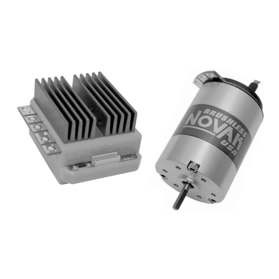
SENSOR-BASED
BRUSHLESS MOTOR SYSTEM
How do you make a great hobby even more fun?
Eliminate motor maintenance & increase efficiency.
We've done it! People have seen the benefits of brushless
motor systems in many industries--now you too will enjoy
the maintenance-free, high-efficiency performance of
brushless that is designed specifically for your R/C car.
We combined the racing technology of our top of the line
speed controls with the efficiency of sensor-based brushless
motors to bring you the Super Sport Brushless Motor System,
giving you a sport-level brushless system with excellent low
speed driveability, extended run time, great torque available
over a broad power band, and Novak relaibility.
Equipped with Novak's Variable Throttle Step Technology
for the smoothest throttle response, One-Touch Set-Up for
ease of programming, and the security of Radio Priority
Circuitry, the Super Sport has it all!
SPECIFICATIONS
Input Voltage
4-7 cells
ESC Case Width
1.32"
ESC Case Depth
1.75"
ESC Case Height
1.05"
ESC Weight
1.70 ounce
(w/o wires)
ESC Power Rating
225 Watts
B.E.C. Voltage
6.0 volts DC/3.0 amps
Wire Length
9 inches
(Battery/Motor)
Signal Harness
9 inches
(replaceable)
ESC Throttle Programs
6
(3 w/Rev. & 3 Fwd/Brk)
Motor Diameter
1.41"
Motor Length
2.08"
Motor Weight
6.40 ounce
Motor Power Rating
196 Watts
Motor Kv
5800 RPM/Volt DC
Motor Kt
0.45 Inch-Ounce/Amp
Motor Commutation
Sensor-Based Electronic
Motor Magnet Material
Neodymium
PRECAUTIONS
• WATER & ELECTRONICS DON'T MIX! Never allow
water, moisture, or other foreign materials to get inside
the speed control, motor, or on the PC Boards.
• CHECK MOTOR SCREWS Remember to check all motor
screws for loosening. The 3 main 4-40 socket head screws
on the shaft end of the motor may become loose after a
few runs of the motor, and will need to be tightened.
• 4 TO 7 CELLS ONLY Never use fewer than 4 or more
than 7 cells (8.4 volts DC) in the main battery pack.
• POWER CAPACITOR REQUIRED The attached external
power capacitor MUST be used with the Super Sport.
Failure to use Power Capacitor will damage speed control
and void the warranty!
• NOVAK MOTORS ONLY The Super Sport ESC has been
specially designed for use with sensor-based Novak
Brushless Motors Only! You may replace motor with any
Novak sensored motor rated less than 225W (ESC's rating).
• NO REVERSE VOLTAGE! Reverse battery polarity will
damage the speed control.
• DISCONNECT BATTERIES WHEN NOT IN USE Always
disconnect the battery pack from the speed control when
not in use to avoid short circuits and possible fire hazard.
• TRANSMITTER ON FIRST Always turn on the power of
your transmitter first so that you will have control of the
radio equipment when you turn on the speed control.
• INSULATE WIRES Always insulate exposed wiring with
heat shrink tubing to prevent short circuits.
• NO SOLVENTS Exposing the speed control or motor to
any type of solvents can damage the exposed material.
SENSOR-BASED DESIGN
The benefits of a sensor-based brushless motor design are:
• CONSTANT ROTOR POSITION KNOWLEDGE Always
knowing what angle the rotor is at, allows instantaneous
response and smooth transitions from neutral to drive.
• SMOOTH/CONTROLLED LOW SPEED DRIVEABILITY
Rotor positioning is key to smooth acceleration without
delivering abrupt and uncontrolled bursts of power.
• STRONG & CONSISTENT BRAKES & STARTING TORQUE
Again, rotor position knowledge results in consistent starts
and stops, without hesitation or inconsistent lag times
before acceleration or braking.
• LOCKED ROTOR & THERMAL PROTECTION Position
and temperature sensors inside motor provide
unparalleled thermal protection for your investment, while
allowing you to run pack after pack without worrying
about overheating the motor, ESC, or magnets.
STEP 1
The Super Sport ESC comes with the industry standard con-
nector on a user-replaceable input harness. This connector
works with all major radio brands. However, with some older
style receivers, the wiring sequence in the plastic connector
must be changed. This is an important step, because the
receiver electronics may be damaged if the sequence is incorrect.
JR • Hitec • Futaba • New KO • Airtronics Z
JR, Hitec, Futaba, new KO, & Airtronics Z receivers do not
need to have the ESC's input harness wire sequence changed.
New Airtronics Z receivers have blue plastic cases & new KO
cases have tabs on the input harness openings as in Figure 1.
• Insert one end of the input harness into receiver with the
BLACK wire toward the outside edge of receiver case.
• Insert opposite end of input harness into ESC with the
WHITE wire toward the 'S' (signal) marking in the ESC's case.
New KO Rx (with tabs)
tabs
white
red
black
Old-style KO • Old-style Sanwa/Airtronics
If your receiver is an older KO or Sanwa/Airtronics, you must
change the sequence of the ESC's input harness wires.
Old Sanwa/Airtronics cases are black in color & Old KO cases
do not have the tab openings, as in Figure 2 above.
• Insert one end of input harness into ESC with the WHITE
wire toward the 'S' (signal) marking in the ESC's case.
• Interchange the red and black wires in the plug plastic at
the opposite end of the input harness as in Figure 3 below.
(1.2 volts DC/cell)
• Insert modified end of the harness into the receiver with
the RED wire toward the outside edge of receiver case.
[33.5 mm]
FIGURE 3
[44.4 mm]
prong until wire and metal socket easily slide out of plastic housing.
[26.7 mm]
[48.2 gr]
@ 25 C trans.temp.
[22.86 cm]
[22.86 cm]
[35.8 mm]
STEP 3
[52.8 mm]
[181.4 gr]
1. MOTOR CAPACITORS & SCHOTTKY NOT NEEDED
Novak brushless motors have built-in motor capacitors,
and like all reversible ESCs, does not use an external
Schottky diode--Schottky diodes damage reversible ESCs.
2. FACTORY-INSTALLED POWER CAPACITOR
WHY POWER CAPACITOR IS NEEDED:
(1pc/multi-pole)
drops ESC operating temperatures by 10-15 F and dissipates noise
& voltage spikes from the ESC's high switching speed. You MUST
use Novak capacitors, because other capacitors with similar ratings
will not provide the same protection. We have done extensive
research to find capacitors with the very best Quality Factors.
Mount Power Capacitor using the included slide-mount
bracket or double-sided tape. To use slide mount bracket,
insert bracket into the channel on the back of the ESC,
and secure Power Capacitor with the included tie-wraps.
3. CONNECT SPEED CONTROL TO RECEIVER
Configure input harness wires and connect ESC to the
THROTTLE CHANNEL of receiver as described in Step 1.
4. CONNECT SPEED CONTROL TO BATTERY PACK
Connect Super Sport's Tamiya-style JST battery connector
to a charged 4 to 7 cell battery pack.
5. CHECK MOTOR SCREW LENGTH
Insert the M3 motor mounting screws that came with
your vehicle through the motor mounting plate in vehicle.
You need to have about 1/8" ( 1/32") of the screw
extending past the mounting plate (2-4mm). Any less
can strip the threads in the motor's end bell, and any
more will cause short-circuiting/damage inside the motor.
6. INSTALL PINION GEAR
Install pinion gear on motor and position set-screw over
flat on end of shaft. Test fit motor in vehicle to align
pinion and spur gears, then tighten pinion gear on shaft.
7. INSTALL MOTOR IN VEHICLE
• Determine the best routing for sensor harness & motor
power wire. Some off-road cars may require unsoldering
motor to route wires through the shock tower--refer to
Step 7, #3–"
• Using the M3 motor screws that came with your
vehicle, attach motor to vehicle's motor mount using
one of the three sets of threaded mounting holes--
a mounting position that will avoid short-circuiting of solder
tabs on conductive surfaces such as aluminum or graphite.
• Check gear mesh for proper amount of play. You want
to have a small amount of free play between the pinion
and spur gears
free play at several positions around the spur gear.
• Avoid using excessive force when tightening motor
screws, as the threaded holes could become stripped.
8. USE SPIRAL WRAP TO BUNDLE/PROTECT WIRES
The included plastic spiral wrap can be used to protect
the 6 Teflon sensor harness wires between the ESC & motor.
You can also use the included spiral wrap and tie-wraps to
bundle the sensor harness & power wires neatly together.
Keep receiver & antenna
as far from motor, servo,
battery, & power wires
as possible.
User-replaceable
input signal
harness plugged
into throttle
channel (#2).
SUPER SPORT SET-UP
CHANGING ESC'S INPUT HARNESS
Old KO Rx (no tabs)
no tabs
white
black
red
With a small standard screwdriver, gently lift plastic
SUPER SPORT SET-UP
BASIC HOOK-UP INSTRUCTIONS
The Power Capacitor
(see GEAR SELECTION on back)
SOLDERING POWER WIRES AT ESC & MOTOR
(about the thickness of piece of paper)
Power Capacitor
tie-wrapped to
slide-mount bracket
Servo
PowerCap
plugged
wires
into
steering
ch. (#1)
(–)
4 to 7 cell
(+)
battery pack
STEP 2
1. DETERMINE BEST ESC MOUNTING LOCATION
Choose a mounting position that keeps power wires away
from the receiver and antenna, and will provide
maximum airflow over heat sinks for proper cooling.
The slide mount channel on the back of the Super Sport's
case can hold the ON/OFF switch or power capacitor.
T
his slide mount lets you mount the power capacitor or the ON/OFF
switch against the side of ESC. The ON/OFF switch can be positioned
facing any of four directions when held by the slide mount. The
switch also has a hole for attaching it with a 4-40 or smaller screw,
or you can use the included double-sided tape.
motor
phase wires
&
sensor harness
ESC
2. SLIDE - MOUNT POWER-CAP. BRACKET (optional)
To use the included P.Cap bracket to mount the capacitor on the back
of the ESC, be sure you have enough space in the desired location.
Slide the bracket into the channel on the ESC. Secure the
power capacitor to the bracket with the included tie-wraps.
heat shink
&
vinyl tubing
insulating
capacitor
leads
3. INSTALL THE SPEED CONTROL & SWITCH
If using the slide mount channel to hold ON/OFF switch,
slide switch into channel facing the desired direction.
Mount the ESC using the included double-sided tape.
slide-mount
switch
4. INSTALL THE RECEIVER AND ANTENNA
Mount receiver as far from ESC, motor, power wires,
battery, and servo as possible. These components all emit
RF noise when throttle is being applied. On graphite or
aluminum, it may help to place receiver on edge with
crystal and antenna as far above chassis as possible.
Note: Mount the antenna as close to the receiver as possible, and trail
any excess wire off the top of the antenna mast––cutting or coiling the
excess antenna wire will greatly reduce radio range.
STEP 4
For proper ESC operation, adjust transmitter as follows:
A. Set HIGH ATV or EPA to maximum setting.
[amount of throw at full throttle]
B. Set LOW ATV, EPA, or ATL to maximum setting.
[amount of throw at full brakes]
C. Set EXPONENTIAL to zero setting.
[throttle channel linearity]
D. Set THROTTLE CHANNEL REV. SWITCH to either position.
E. Set THROTTLE CHANNEL TRIM to middle setting.
[adjusts neutral position/increases or decreases coast brakes]
F. Set ELECTRONIC TRIGGER THROW ADJUSTMENT to
70% throttle and 30% brake throw (or 7:3).
[adjusts trigger throw electronic/digital pistol-grip transmitters]
G. Set MECHANICAL TRIGGER THROW ADJUSTMENT
to position with 2/3 throttle and 1/3 brake throw.
[adjusts trigger throw on mechanical/analog pistol-grip transmitters]
STEP 5
With ESC connected to receiver & a charged battery pack:
1. TURN ON THE TRANSMITTER'S POWER
2. PRESS & HOLD SPEED CONTROL'S SET BUTTON
3. TURN ON THE SPEED CONTROL'S POWER
With transmitter throttle at neutral, and still pressing the
".
SET button slide the ON/OFF switch to ON position.
4. HOLD ESC'S SET BUTTON UNTIL RED LED IS ON
Continue pressing SET button until the Super Sport's red
select
status LED turns solid red.
5. RELEASE ESC'S SET BUTTON WHEN LED IS RED
6. PULL TRANSMITTER THROTTLE TO FULL-ON POSITION
Hold it there until the green status LED turns solid green.
--check
Note: Motor will not run during programming even if connected.
7. PUSH TRANSMITTER THROTTLE TO FULL-BRAKES
Hold it there until the green status LED blinks green.
8. RETURN TRANSMITTER THROTTLE TO NEUTRAL
Amber, green, & red status LEDs will turn on solid,
indicating that proper programming has been completed.
ESC returns to neutral and red status LED will turn on solid.
NOTE: If transmitter settings are changed, programming must be repeated.
If you experience any problems, turn off ESC and repeat programming.
Trail excess wire off top
of antenna mast
Status LEDs
One-Touch
Set-Up
button
Black power wire
(battery negative)
Sensor
Harness
bundled with
Spiral Wrap
Tamiya-style
Red power wire
battery connector
(battery positive)
SUPER SPORT SET-UP
MOUNTING SPEED CONTROL
Super Sport
brushless
system
installed in
Tamiya
touring sedan
for first win
@ Tamiya
4 hour
Enduro Race
power
capacitor
tie-wrapped
to bracket
solder tabs
SUPER SPORT SET-UP
TRANSMITTER ADJUSTMENTS
SUPER SPORT SET-UP
ONE-TOUCH PROGRAMMING
Orange power wire
(motor phase 'C')
Blue power wire
(motor phase 'A')
Yellow power wire
(motor phase 'B')
ESC faceplate
close-up
Status LEDs:
Blue LED
Amber LED
Green LED
Red LED
Advertisement

Related Manuals for NOVAK SUPER SPORT


Summary of Contents for NOVAK SUPER SPORT
- Page 1 This is an important step, because the The slide mount channel on the back of the Super Sport’s receiver electronics may be damaged if the sequence is incorrect. case can hold the ON/OFF switch or power capacitor.
- Page 2 Use soldering iron to apply heat to exposed wire that is metal The Super Sport brushless motor system is guaranteed to be free from defects orange blue barb in materials or workmanship for a period of 120 days from the original date of extending past bottom of PCB, and begin adding solder purchase (verified by dated, itemized sales receipt).