Advertisement
Quick Links
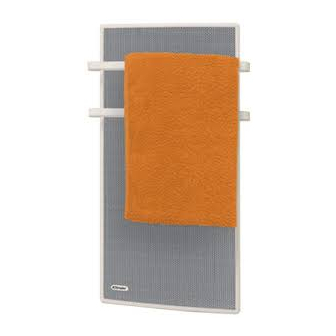
Apollo Electronic Radiant Panel Heater
:
Models
APL100 / APL150
Dimensions and Specification
Model
Loading
Height
(kW)
(mm)
APL100
1.0
830
APL150
1.5
1040
THESE INSTRUCTIONS SHOULD BE READ CAREFULLY AND RETAINED FOR FUTURE REFERENCE
IMPORTANT SAFETY ADVICE
•
When using electrical appliances, basic precautions should always be
followed to reduce the risk of fire, electrical shock, and injury to
persons, including the following:
•
WARNING THE SURFACES OF THIS HEATER CAN BE HOT
Momentary contact with any part of the heater should not cause injury.
However, aged or infirm persons or young children should not be left
unsupervised in the vicinity of the heater unless a suitable guard is
fitted
•
IMPORTANT – If this heater is installed in a room containing a bath or
shower, it should be so installed that switches and other controls
cannot be touched by a person using a bath or shower – to comply
with this requirement see 'Lock the Control Cover' section on page 2.
•
If you use this heater in conjunction with an external thermal control, a
programme controller, a timer or any other device which switches the
heat on automatically, observe all safety warnings AT ALL TIMES since
a fire risk exists when the heater is accidentally covered or displaced
•
The installation of this product should be carried out by an electrician
or competent person and be in strict accordance with the current IEE
Wiring Regulations and relevant Building Regulations
•
This heater must not be mounted within 150mm of curtains and other
combustible materials or 100mm from a shelf or overhang
•
NEVER cover or obstruct the front panel in any way
•
DO NOT cover the heater – Do not place material or garments on the
heater or obstruct the air circulation around the heater
•
Before connecting the heater check that the supply voltage is the same
as that stated on the heater
•
The heater must be installed in accordance with these instructions
•
The heater must be mounted using the wall bracket supplied. The
heater should only be operated in the upright position
•
The heater should be positioned in accordance to the clearances
stated in these instructions
•
DO NOT locate this heater immediately beneath a fixed socket outlet
Electrical
The wires in the mains lead are coloured in accordance with the following code:
GREEN & YELLOW
EARTH
BLUE
NEUTRAL
BROWN
LIVE
BLACK
PILOT WIRE
(See also 'Pilot Wire Connection')
The heater is fitted with a length of flexible cable for connection to the fixed wiring of
the premises through a suitable connection box positioned adjacent to the heater.
The supply circuit to each heater must incorporate a double pole isolating switch having
a contact separation of at least 3mm
Pilot Wire Connection
The BLACK control wire is designed to carry a signal from slot in or wall mounted Dimplex
programmers. If, however a programmer is not being used, the pilot wire should be
isolated in accordance with the current IEE Wiring Regulations.
Do NOT connect the BLACK pilot wire to earth
Any 240V insulated cable may be used to link pilot wires around the ring main. A low
signal current is used. Suitable connections would be either an additional single core wire
marked or colour coded appropriately or use a 4 core cable throughout the ring main.
Please refer to the relevant programmer installation and operating instructions for further
details on pilot wire connection
Width
Depth
X
Y
(mm)
(mm)
(mm)
(mm)
440
90
248
96
440
90
248
96
Installation and Operating Instructions
Z
Weight
(mm)
(kg)
96
96
General
The compact Apollo range of radiant panel heaters are designed to
provide comfortable radiant heat, with the added benefit of two rails for
drying towels, in both domestic and commercial applications.
Wall Mounting / Installation
The heater should be positioned observing the minimum clearances
stated around the heater.
(see also 'Electrical' section)
The wall bracket supplied with the heater must be used
1.
Remove wall mounting bracket from back of heater by de pressing
the two spring latches at the top of the heater (see Fig.1)
2.
Fix wall bracket securely to wall via the three or four holes in the
bracket with the appropriate fixings for the wall type (see Fig.2)
3.
Present heater to wall bracket and engage the two lower slots first.
Then line up and push in the top two slots until the spring latches
click in to place
Model
APL100
APL150
IP24
Issue 1 January 2005
Fig.1
Fig.2
A
B (Minimum)
468
225
618
285
Advertisement

Related Manuals for Dimplex Apollo APL100


Summary of Contents for Dimplex Apollo APL100
-
Page 1: Installation And Operating Instructions
3mm Pilot Wire Connection The BLACK control wire is designed to carry a signal from slot in or wall mounted Dimplex programmers. If, however a programmer is not being used, the pilot wire should be isolated in accordance with the current IEE Wiring Regulations. - Page 2 Note: If the programme function is selected but no programming device is being used, the heater will function in comfort mode The following Dimplex programmers are available Pilot Wire Wall Mounted Controller (2 Zone) – Part no. RX010006 MBS Wall Mounted Programmer (2 Zone) – Part no. RX010007 MBS Slot in Receiving Cassette –...