Table of Contents
Advertisement
Quick Links
Advertisement
Table of Contents

Related Manuals for Acer AO756


Summary of Contents for Acer AO756
- Page 1 AO756 V5-171 S E R V I C E G U I D E G U I D E...
-
Page 2: Table Of Contents
Table of Contents Chapter 1. Hardware Specifications and Configurations Features ............1-2 Notebook Tour . - Page 3 Internal Microphone Failure ........4-11 USB Failure (USB 2.0) .
- Page 4 AO756 / V5-171 ........
- Page 5 Revision History Please refer to the table below for the updates made on this service guide. Date Chapter Updates Service guide files and updates are available on the Acer/CSD website. The information in this guide is subject to change without notice. Copyright Copyright ©...
- Page 6 Conventions The following conventions are used in this manual: WARNING: Indicates a potential for personal injury. CAUTION: Indicates a potential loss of data or damage to equipment. IMPORTANT: Indicates information that is important to know for the proper completion of a procedure, choice of an option, or completing a task.
-
Page 7: General Information
General Information This Service Guide provides all technical information relating to the basic configuration for Acer's global product offering. To better fit local market requirements and enhance product competitiveness, your regional office may have decided to extend the functionality of a machine (e.g. - Page 8 CHAPTER Hardware Specifications and Configurations Hardware Specifications and Configurations ....1-2 Features ............1-2 Notebook Tour .
-
Page 9: Chapter 1. Hardware Specifications And Configurations
Hardware Specifications and Configurations Features The following is a summary of the computer’s many features: Operating System ® • Genuine Windows 7 Starter (32-bit) ® • Genuine Windows 7 Home Basic (64-bit) ® • Genuine Windows 8 (32-bit/64-bit) Platform ® •... -
Page 10: Privacy Control
Privacy Control • BIOS user, supervisor, HDD passwords • Kensington lock slot Storage Subsystem • Hard Disk Drive 320/500GB or larger • 2-in-1 card reader, supporting: Secure Digital™ (SD) Card, MultiMedia Card™ (MMC) Graphics • Dual independent display support • 16.7 million colors •... -
Page 11: Dimensions And Weight
ACPI 2.0 CPU power management standard: supports Standby and Hibernation power-saving modes Battery • 37W 2500mAh 4-cell Li-Polymer battery pack • Battery life: 5.2 hours for V5-171; 4.2 hours for AO756 @MM07 utility ® • ENERGY STAR Power Adapter •... - Page 12 I/O Ports • 2-in-1 card reader • One USB 3.0 port with Two USB 2.0 ports for V5-171 • Three USB 2.0 ports for AO756 ® • HDMI port with HDCP support • Headphone/speaker jack, supporting 3.5 mm headset with built-in microphone for Acer smart handhelds •...
-
Page 13: Notebook Tour
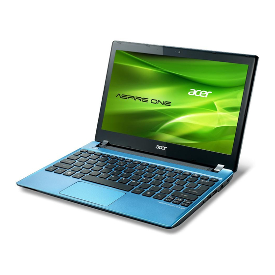
Notebook Tour Top View Figure 1:1. Top View Icon Item Description Webcam Web camera used for video communications. Receives audio input for sound recording or voice Microphone chatting. Power Button Press to turn on the system. Touch-sensitive pointing device that functions like a Touchpad computer mouse. -
Page 14: Front View
Front View Figure 1:2. Closed Front View Icon Item Description Insert a memory card such as Secure Digital (SD) and MultiMedia Card (MMC) for external 2-in-1 storage. MULTIMEDIACARD Card Reader NOTE: Only one card can be inserted at a time. Indicates the computer power status: •... -
Page 15: Left View
Connects to a VGA cable for external video output. Use for air flow. Air Vents CAUTION: Do not cover the air vents. HDMI Port Supports high-definition digital video connections. Connects to USB 2.0 devices (AO756). USB Ports Connects to USB 3.0 devices (V5-171). Hardware Specifications and Configurations... -
Page 16: Right View
Right View Figure 1:4. Right View Icon Item Description Headset Jack Connects to a headset. USB Ports Connects to USB 2.0 devices. DC-In Jack Connects to an AC adapter. Connects to a Kensington-compatible computer security lock. NOTE: Wrap the computer security lock cable Kensington Lock around an immovable... -
Page 17: Base View
Base View Figure 1:5. Base View Icon Item Description Battery Bay Houses the computer battery pack. Battery Release Insert a suitable tool into the latch and slide to Latch release the battery. Houses the computer HDD, main memory, and Base Door antenna module. -
Page 18: Touchpad Basics
Touchpad Basics Figure 1:6. Touchpad Item Description Move your finger across the touchpad to move the cursor. Touchpad Tapping on the touchpad is the same as clicking the left mouse button. Press the left button to perform selection and execution Left Button functions. -
Page 19: Keyboard Basics
Keyboard Basics Figure 1:7. Keyboard Item Description When Caps Lock is on, all alphabetic characters are Caps Lock Key typed in uppercase. Use with other key combinations to perform special Function Key functions. • Press to launch the Start menu. Windows Key •... - Page 20 Windows Key The table below shows the different functions that Windows key combinations can do: Table 1:2. Windows Key Combinations Key Combination Description Opens or closes the Start menu. Opens the Run dialog box. + <R> Minimizes all windows. + <M> Undo immunize all windows.
- Page 21 Hotkeys Hotkeys or function key combinations can be used to access computer control functions such as screen brightness, volume, and multimedia playback controls. Table 1:3. Hotkey Combinations Function Key Combination Icon Description Communication Enables/disables wireless connectivity of <Fn> + <F3> Switch your computer.
-
Page 22: System Block Diagram
System Block Diagram Figure 1:8. System Block Diagram 1-15 Hardware Specifications and Configurations... -
Page 23: Specifications Table
Specifications Table Computer specifications Item Metric Imperial Dimensions Length 285 mm 11.22 in Width 202 mm 7.95 in Height (front to rear) 20.95 mm 0.82 in Weight (equipped with optical 1.4 kg 3.09 lbs drive, flash drive, and battery) Input power Operating voltage 18.55 V ~ 19.95V Operating current... - Page 24 Item Metric Imperial NOTE: Applicable product safety standards specify thermal limits for plastic surfaces. The computer operates well within this range of temperatures. System Board Major Chips Item Specification Core logic Intel Panther Point-M PCH Intel integrated Broadcom BCM57785XB0KMLG QFN 68P E-LAN CTRL USB 2.0 2 USB2.0 &...
- Page 25 Processor Specifications Speed Cache Core Item Cores Package Speed (FSB/ Tech Size Voltage DMI/QBI) Intel Celeron 1.4G dual 5GT/s 32nm BGA1023 0.7-1.2V Pentium Dual 1.5G dual 5GT/s 32nm BGA1023 0.7-1.2V Core 987 Pentium Dual 1.3G dual 5GT/s 32nm BGA1023 0.7-1.2V Core 967 i5-2467M 1.6G...
- Page 26 CPU Fan True Value Table (Tj=100) CPU Temp Fan Speed (RPM) SPL Spec (dBA) 3400 3700 4100 4700 5200 5400 Pro-hot: On= 99°C; OFF= 91°C OS shut down at 100 °C; H/W shut down at 92 °C System Memory Item Specification Memory controller Intel Sandy/IVY Bridge Processor...
- Page 27 Memory Combinations Slot 1 (MB) Slot 2 (MB) Total Memory (MB) 1024 1024 2048 2048 2048 1024 2048 3096 2048 2048 4096 4096 4096 2048 4096 6154 4096 4096 8192 Video Interface Item Specification Chipset Package Interface Compatibility Sampling rate BIOS Item Specification...
- Page 28 LAN Interface Item Specification LAN Chipset Broadcom BCM57785XB0KMLG LAN connector type RJ45 LAN connector location RJ45 on the left side Features Supports 10/100/1000BASE-T full-duplex/half-duplex MAC Keyboard Item Specification Type AF1S Total number of keypads 84-US/85-UK /88-JA Windows logo key Internal & external keyboard Plug USB keyboard to the USB port directly: Yes work simultaneously •...
- Page 29 Hard Disk Drive (List all AVL components) Item Specification Vendor & HTS543232A7A HTS545050A7E Model Name ST320LT012 WD5000LPVT- 22G33T ST320LT020 WD3200LPVT- 22G33T Capacity 320G 500G (GB) Bytes per 512Bytes 4096Bytes sector 4096Bytes 4096Bytes 4096Bytes 4096Bytes Data heads Drive Format Disks Spindle 5400RPM speed (RPM) Performance Specifications...
- Page 30 Super-Multi Drive Interface (N/A) Item Specification Vendor & Model name Performance Specification Transfer rate (KB/sec) Buffer Memory Interface Applicable disc format Loading mechanism Power Requirement Input Voltage LED 11.6” Item Specification LCD AUO B116XTN04.0 (H/W:0A) Vendor/Model name Screen Diagonal (mm) 293.8 mm Active Area (mm) 256.125 mm x 144.0 mm...
- Page 31 LED 11.6” (Con’t.) Item Specification LCD CMI N116BGE-L32 Vendor/Model name Screen Diagonal (mm) 293.8 mm Active Area (mm) 259.125 mm x 146.80 mm Display resolution (pixels) 1366 x 3(RGB) x 768 Pixel Pitch (mm) 0.1875 mm × 0.1875 mm 200 typ. Luminance, wHITE Contrast Ratio 500 typ...
- Page 32 LED 11.6 (Con’t.) Item Specification AUO B116XW03 V2 (H/W:1B) Vendor/Model name Screen Diagonal (mm) 293.8 mm Active Area (mm) 256.125 mm x 144.0 mm Display resolution (pixels) 1366 x 3(RGB) x 768 Pixel Pitch (mm) 0.1875 mm × 0.1875 mm 200 typ.
- Page 33 LED 11.6” (Con’t.) Item Specification CMI N116BGE-L42 Vendor/Model name Screen Diagonal (mm) 293.8 mm Active Area (mm) 259.125 mm x 146.80 mm Display resolution (pixels) 1366 x 3(RGB) x 768 Pixel Pitch (mm) 0.1875 mm × 0.1875 mm Luminance, wHITE 200 cd/m typ.
- Page 34 Supported Resolution (GPU: Include all supported resolution) Resolution 16 bits 32 bits 640x480p/60Hz 16:9 800x600p/60Hz 16:9 1024x768p/60Hz 16:9 1280x600/60Hz 16:9 1280x720/60Hz 16:9 1280x768/60Hz 16:9 1360x768/60Hz 16:9 1366x768/60Hz 16:9 Legend: V = Supported; X = Not supported Bluetooth Interface (N/A) Item Specification Chipset Data throughput...
- Page 35 Camera Item Specification • Chicony, CNFB1D921004970LH • Chicony, CNFB1D721004970LH • Lite-on, 11P2SF167 Vendor and Model • Lite-on, 12P2SF105 • Suyin, HF1016-A21U-OV02 • Suyin, HF1016-T821-HN01 Type Mini Card Item Specification Number supported Features 1 mini card slot (1 for WLAN & BT or WLAN) 3G Card (N/A) Item Specification...
- Page 36 Wireless Module 802.11b/g/n Item Specification Chipset Qualcomm Broadcomm 1 transmitter and 1 receiver • 802.11g: 54Mbps with fall back of allow data rates supporting up to 48, 36, 24, 18, 12, 9, 6Mbps 150 Mbps downstream and 150 • 802.11b: 11Mbps with fall back Mbps upstream PHY rates.
- Page 37 HDMI Port Item Specification Compliance level HDMI 1.4 Data thoroughput Up to 16.7 million colors Number of HDMI port(s) Location JHDMI1 at the bottom AC Adapter Item Specification 40 W Input rating 40 W: 1.2A at 100V Maximum input AC current No damage;...
- Page 38 Card Reader Item Specification Chipset BCM57785XA0KMLG Package QFN68 • SD, miniSD, microSD™ Maximum supported size • SDHC, miniSDHC, microSDHC • SDXC, microSDXC 2 in 1 card reader, supporting: Features • Secure Digital™ (SD) Card • MultiMediaCard™ (MMC) System LED Indicator Item Specification Lock...
- Page 39 System Interrupt Specification Hardware IRQ System Function IRQ0 IRQ1 IRQ2 IRQ3 IRQ4 IRQ6 IRQ7* IRQ8 IRQ9* IRQ10* IRQ11 IRQ12 IRQ13 IRQ14 IRQ15 NOTE: Default configuration, audio possible configurations are IRQ5, IRQ7, IRQ9, IRQ10, or none. Hardware Specifications and Configurations 1-32...
- Page 40 System IO Address Map I/O Address (hex) System Function (Shipping Configuration) 000 - 00F DMA controller no. 1 & PCI bus 010 - 01F Motherboard resources no. 1 020 - 021 Interrupt controller no. 1 022 - 024 Unused 025 - 03F Unused 02E - 02F Motherboard resources no.
- Page 41 System IO Address Specification (N/A) I/O Address (hex) System Function (Shipping Configuration) 3E2 - 3FF 400-4CF 4D0-4D1 680-6FF 840-847 C00-C01 C50-C52 CD0-CDB D00-FFFF 2000-207F 2000-207F 3000-30FF 3100-310F 3110-3117 3118-311F 3120-3123 3124-2127 FD60-FD63 Hardware Specifications and Configurations 1-34...
- Page 42 CHAPTER Diagnostic Utilities System Utilities ......... .2-2 BIOS Setup Utility .
-
Page 43: Chapter 2. System Utilities
System Utilities BIOS Setup Utility The BIOS Setup Utility is a hardware configuration program built into a computer’s BIOS (Basic Input/Output System). The BIOS utility is pre-configured and optimized so most users do not need to run this utility. However, if configuration problems occur, you may need to run the BIOS utility. To activate the BIOS Utility, press F2 during POST (power-on-self-test) when the “Press <F2>... -
Page 44: Bios
BIOS The following is a description of the menu tabs found on the InsydeH20 BIOS Setup Utility screen. NOTE: The screens provided are for reference only. Actual values may differ by model. Information The Information tab displays a summary of the computer hardware information. InsydeH20 Setup Utility Rev. - Page 45 Parameter Description Asset Tag Number Displays the tag number of the system. Product Name Displays the product name of the system. Manufacturer Name Displays the system manufacturer. UUID Displays the UUID (Universally Unique Identifier). System Utilities...
-
Page 46: Main
Main The Main tab allows the user to set the system time and date, enable or disable boot option, and enable or disable recovery. InsydeH20 Setup Utility Rev. 3.7 Information Main Security Boot Exit Item Specific Help System Time : [19:03:49] System Date : [01/01/2012]... -
Page 47: Security
Security The Security tab allows the user to configure and protect the computer from unauthorized use. InsydeH20 Setup Utility Rev. 3.7 Information Main Security Boot Exit Item Specific Help Supervisor Password Is: Clear User Password Is: Clear HDD Password Is: Clear Install or Change the password and the length of password must be greater or... - Page 48 Setting a Password Perform the following to set the supervisor password: ↑ ↓ Use the keys to highlight the Set Supervisor Password parameter and press Enter. The Set Supervisor Password dialog box appears. Set Supervisor Password Enter New Password Confirm New Password Figure 2:4.
- Page 49 NOTE: The same procedures apply in setting the user password and HDD password. When the supervisor password is set, the Set User Password and Password on Boot parameters are enabled for users to configure. Changing a Password Perform the following to change a password: NOTE: Below are the procedures for changing the supervisor password.
- Page 50 Removing a Password Perform the following to remove a password: NOTE: Below are the procedures for removing the supervisor password. The same procedures apply in removing the user and HDD passwords. When the supervisor password is removed, the user password is automatically removed. ↑...
-
Page 51: Boot
Boot The Boot tab allows the user to configure the order of boot devices used to load the operating system. ↑ ↓ keys to select a device and press F5 or F6 to change the value. InsydeH20 Setup Utility Rev. 3.7 Information Main Security... -
Page 52: Exit
Exit The Exit tab allows the user to save or discard changes and quit the BIOS Setup Uitility. InsydeH20 Setup Utility Rev. 3.7 Information Main Security Boot Exit Item Specific Help Exit Saving Changes Exit Discarding Changes Load Setup Defaults Exit System Setup and save your changes. -
Page 53: Bios Flash Utilities
BIOS Flash Utilities BIOS Flash memory updates are required for the following conditions: • New versions of system programs • New features or options • Restore a BIOS when it becomes corrupted. Use the Flash utility to update the system BIOS Flash ROM. Perform the following to run a BIOS Flash update: Prepare a bootable USB HDD/FDD. -
Page 54: Dos Flash Utility
DOS Flash Utility NOTE: Plug the AC power adaptor to a power source before performing the DOS Flash Utility. Perform the following to use the DOS Flash Utility: In Windows OS, unzip the compressed BIOS ROM package (e.g. in this case, “Q1VZC102.zip”). - Page 55 Insert the USB HDD and reboot the computer in DOS mode. If necessary, execute the “dir” command to find the batch file. C:\Q1VZC102\DOS>dir Volume in drive C is USB_8GB Volume Serial Number is 3666-33A4 Directory of C:\Q1VZC102\DOS <DIR> 03-27-2012 18:46 . <DIR>...
- Page 56 The system restarts automatically when finished. IMPORTANT: Ensure the AC power adaptor is connected to the power source. • If the Warning message below is shown, check if the AC power adaptor is properly • connected or not. C:\>cd Q1VZC102\DOS C:\Q1VZC102\DOS>BIOS.bat Warning: No AC Connected This process requires AC power to avoid an accidental power-off...
-
Page 57: Winflash Utility
WinFlash Utility NOTE: Plug the AC power adaptor to a power source before performing the WinFlash Utility. Perform the following to use the WinFlash Utility: Boot into Windows OS and search for WinFlash Utility file. Q1VZC102 Figure 2:18. Browsing for WinFlash Utility Double-click on the utility file. - Page 58 After click OK, it will auto flash BIOS and EC. Figure 2:21. Updating Flash BIOS When flashing is complete, WinFlash will close all AP and restart the system. CAUTION: Do not turn off the computer during the Flash process. • Do not put the system into standby or hibernation mode.
- Page 59 Winflash Error and Warning Messages • If the AC adapter is not plugged in before Winflash starts, the following message is shown: Figure 2:22. AC Detect Error Message • After executing Winflash, if the AC adapter is not plugged and the battery power is low, the following message is shown: Figure 2:23.
-
Page 60: Miscellaneous Tools
1. Read DMI Information from Memory: Input: dmitools /r Output: Manufacturer (Type1, Offset04h): Acer Product Name (Type1, Offset05h): V5-171 (for Core i CPU) AO756 (for PDC/ICP) Serial Number (Type1, Offset07h): 01234567890123456789 UUID String (Type1, Offset08h): xxxxxxxx-xxxx-xxxx-xxxx- xxxxxxxxxxxx 2. Write Product Name to EEPROM Input: dmitools /wp V5-171 3. - Page 61 4. Write UUID to EEPROM (Create UUID from Intel WFM20.pdf) Input: dmitools /wu 5. Write Asset Tag to EEPROM Input: dmitools /wa Acer Asstag NOTE: When running examples 2 ~ 5, restart the system to make the new DMI data effective. System Utilities 2-20...
-
Page 62: Hdd/Bios Password
HDD/BIOS Password This section provides details about unlocking HDD password and removing the BIOS passwords. Unlocking the HDD NOTE: If the HDD password is incorrectly entered three times, the HDD is locked and the Harddisk Security dialog box appears. Harddisk Security Primary Master TOSHIBA... - Page 63 Execute UnlockHD.exe to generate an unlock password. Use the following command: UnlockHD [key code] with the code noted in step 3, Figure 2:28. C:\UnlockHD 54986933 Password: 41684315 Figure 2:28. Execute UnlockHD.exe Take note of the generated unlock password. On the original device, enter the unlock password in the Enter Unlock Password dialog box.
-
Page 64: Clearing The Password Check And Bios Password
Clearing the Password Check and BIOS Password Clearing the Password Check The password check can be removed by shorting the “R74” point with a metal instrument. Open the base door. Locate R74 point near the memory module and fan module. Use an electronic conductivity tool to bridge the two points of the jumper. - Page 65 Cleaning BIOS Passwords To clean the User or Supervisor password, perform the following: At the command prompt, type CP.exe. The Clean Password Utility is shown. Figure 2:31. Clean BIOS Password Press 1 or 2 to clean the desired password shown on the screen. The screen displays if the function is successful or a failure.
-
Page 66: Crisis Utility Sop
Crisis Utility SOP When to Use the Crisis SOP • When the system hangs while updating BIOS • When power failure occurs and the system shuts down while updating BIOS • When the system cannot boot normally after updating BIOS (e.g. a black screen appears without a POST logo, etc.) Creating a USB Flash Crisis Disk To create a Crisis USB flash disk, perform the following:... - Page 67 In the dialog shown below, set the following options: • File System: Choose “FAT32” • Format Options: Select “Quick Format” Then, click Start to execute the formatting operation. Figure 2:34. Format USB Flash Disk (2 of 2) Click OK to confirm when the following dialog is shown. Figure 2:35.
- Page 68 In Windows OS, unzip the compressed BIOS ROM package (e.g. in this case, “Q1VZC102.zip”). Copy the files “Q1VZC102.bin” and “KAFE102A.ROM” to the root directory of the USB flash disk. Figure 2:37. Copy *.BIN Files to USB Disk Press + <R> and type “cmd” to bring out the Command Line window. Figure 2:38.
-
Page 69: Using The Crisis Utility Disk
Using the Crisis Utility Disk Turn off the target machine and unplug the AC adapter. Figure 2:40. Ensure Power is Off Plug the USB flash disk. Figure 2:41. Plug the USB Flash Disk Press and hold <Fn> and <Esc>, then plug in the AC adapter. Figure 2:42. - Page 70 As <Fn> and <Esc> keys are pressed, press the Power button to turn on the target machine. Wait for 3~5 seconds to make sure the system fan is in full speed before releasing <Fn> and <Esc> keys. Figure 2:43. Press the Power Button Wait for 3~5 minutes for the system to complete the crisis operation.
- Page 71 CHAPTER Jumper and Connectors Location Jumper and Connector Locations ......3-2 Mainboard Top View ..........3-2 Mainboard Bottom View .
-
Page 72: Chapter 3. Jumper And Connector Locations
Jumper and Connector Locations Mainboard Top View JLVDS1 PJP1 JIO1 JLED1 JREAD1 JSPK1 JKB1 Figure 3:1. Mainboard Top Table 3:1. Mainboard Top Jumper and Connectors Item Description JLVDS1 LVDS Connector JREAD1 2 in 1 Card Reader Connector JSPK1 Speaker Connector JKB1 Keyboard Connector JLED1... -
Page 73: Mainboard Bottom View
Mainboard Bottom View PJP2 JFAN1 JRJ1 JCRT1 JDIMM2 JDIMM1 JHDD1 JHDMI1 JUSB1 JTP1 JMINI1 Figure 3:2. Mainboard Bottom Table 3:2. Mainboard Bottom Jumper and Connectors Item Description Item Description PJP2 Battery Connector JMINI1 Mini Card Connector JFAN1 Fan Connector JCRT1 D-SUB Connector JRJ1 RJ45 Connector... -
Page 74: Led Board View
LED Board View Top View JLED1 Bottom View LED1 LED2 Figure 3:3. LED Board Jumper Table 3:3. LED Board Jumper Item Description JLED1 LED/B FFC Hot-bar LED1 System State LED LED2 Battery State LED Jumper and Connector Locations... -
Page 75: Io Board View
IO Board View Top View Bottom View JMIC1 JUSB1 JUSB2 JCOM1 JIO1 Figure 3:4. IO Board Jumper Table 3:4. IO Board Jumper Item Description JMIC1 Internal MIC Connector JUSB1 USB2.0 Connector JUSB2 USB2.0 Connector JCOM1 Combo Jack Connecotr JIO1 IO/B FFC Hot-bar Jumper and Connector Locations... -
Page 76: Hdd Board View
HDD Board View Top View Bottom View JHDD1 JHDD2 Figure 3:5. IO Board Jumper Table 3:5. IO Board Jumper Item Description JHDD1 HDD Connector JHDD2 HDD/B FFC Hot-bar Jumper and Connector Locations... -
Page 77: Clear Cmos Jumper
Clear CMOS Jumper Clear CMOS Figure 3:6. Clear CMOS Table 3:6. Clear CMOS Jumper Item Description Clear CMOS Jumper (BOT) C163 Clear CMOS Jumper (TOP) Jumper and Connector Locations... - Page 78 CHAPTER Troubleshooting Troubleshooting .........4-2 General Information .
-
Page 79: General Information
Troubleshooting This chapter contains information about troubleshooting common problems associated with the tablet. General Information The following procedures are a guide for troubleshooting computer problems. The step by step procedures are designed to be performed as described. NOTE: The diagnostic tests are intended to test only Acer products. Non-Acer products, prototype •... -
Page 80: Power On Issues
Power On Issues If the system does not power on, perform the following: Start Check AC/Batt only Swap AC/Battery power on Check Power/B Swap Power SW/B Whether OK Swap M/B Figure 4:1. Power On Issues Computer Shuts Down Intermittently If the system powers off at intervals, perform the following. Makes sure the power cable is properly connected to the computer and the electrical outlet. -
Page 81: No Display Issues
No Display Issues If the system does not display, perform the following: Start Go to no power Replace LCD panel/cable Trouble shooting Power on panel/cable step Replace M/B module well Connect it well connected Replace RAM module OK module Lcd cable well Connect it well connected... - Page 82 Reseat the memory modules. Remove the drives (refer to Maintenance Flowchart on page 5-4). If the issue is still not resolved, refer to Online Support Information on page 8-2. Abnormal Video If the video appears abnormal, perform the following: Boot the computer. •...
-
Page 83: Lcd Picture Failure
LCD Picture Failure If the LCD picture fails, perform the following: Start Swap Check LCD LCD cable/ module LCD panel Swap M/B Figure 4:3. LCD Picture Failure Troubleshooting... -
Page 84: Internal Keyboard Failure
Internal Keyboard Failure If the internal keyboard fails, perform the following: Start Connect Keyboard FPC well connected? it well Replace Keyboard OK? keyboard Replace M/B Figure 4:4. Internal Keyboard Failure Troubleshooting... -
Page 85: Touchpad Failure
Touchpad Failure If the touchpad fails, perform the following: Start Re-assemble Check M/B T/P FFC the T/P FFC to M/B Swap/Re-assemble Check Logic the T/P board or Upper T/P FFC Swap M/B Figure 4:5. Touchpad Failure Troubleshooting... -
Page 86: Internal Speaker Failure
Internal Speaker Failure If the internal speakers fail, perform the following: Start Re-assemble the Check M/B SPK cable SPK cable to M/B Check SPK Swap SPK module whether Swap M/B Figure 4:6. Internal Speaker Failure Sound Problems Perform the following: Boot the computer. - Page 87 Navigate to Start > Control > Panel > Hardware and Sound > Sound. Confirm that Speakers is selected as the default audio device (green check mark). NOTE: If Speakers is not shown, right-click on the Playback tab and select Show Disabled Devices (clear by default).
-
Page 88: Internal Microphone Failure
Internal Microphone Failure If the internal microphone fails, perform the following: Start Re-assemble the Check M/B MIC cable MIC cable to M/B Check MIC Swap MIC module where module Swap M/B Figure 4:7. Internal Microphone Failure Check that the microphone is enabled. Navigate to Start > Control Panel > Hardware and Sound >... -
Page 89: Usb Failure (Usb 2.0)
USB Failure (USB 2.0) If the USB fails, perform the following: Start Check USB Re-assemble USB FFC to USB Connect Swap USB/B Check USB/B Replace Check USB CONN is well USB CONN Swap M/B Figure 4:8. USB Failure Troubleshooting 4-12... -
Page 90: Wireless/Bt Function Test Failure
Wireless/BT Function Test Failure If the wireless/BT function fails, perform the following: Start Re-assemble the Check W/L antenna to W/L antenna to W/L combine card combine card Swap the antenna Check antenna Swap the W/L Check W/L combine card combine card Swap M/B Figure 4:9. -
Page 91: 2-In-1 Card Function Test Failure
2-in-1 Card Function Test Failure If the 2-in-1 card function fails, perform the following: Start Repair the Card read Card read conn well solder conn Swap M/B Card read Chip ok card read Chip Swap M/B Figure 4:10. 2-in-1 Card Function Failure Troubleshooting 4-14... -
Page 92: Unit Thermal Failure
Unit Thermal Failure If the unit thermal fails, perform the following: Start Fan cable Connect it well Well connected Replace fan Fan ok Thermal Insert is well well insert Replace M/B Figure 4:11. Unit Thermal Failure 4-15 Troubleshooting... -
Page 93: Cosmetic Failure
Cosmetic Failure If the cosmetic fails, perform the following: Start LCD cover Swap LCD cover Swap LCD bezel LCD bezel Swap Upper Upper Swap Lower Lower Function Test Figure 4:12. Cosmetic Failure Troubleshooting 4-16... -
Page 94: Other Functions Failure
Other Functions Failure If other functions such as the CRT switch, HDMI switch, LAN connection, external microphone, or external speaker fail, perform the following: Check if the drive is ok. Check if the test fixture is ok. Swap the mainboard. BIOS Problems Forget BIOS Password If the user forgets the BIOS password, discharge CMOS by shorting the CMOS connector. -
Page 95: Intermittent Problems
If HDD information is missing from the BIOS, the drive may be defective and should be replaced. Replace the Motherboard. If the issue is still not resolved, refer to Online Support Information on page 8-2. Intermittent Problems Intermittent system hang problems can be caused by a variety of reasons that have nothing to do with a hardware defect, such as: cosmic radiation, electrostatic discharge, or software errors. - Page 96 CHAPTER Service and Maintenance Service and Maintenance ........5-3 Introduction .
- Page 97 CHAPTER Service and Maintenance (cont.) Speaker Installation ......... 5-53 Keyboard Removal .
-
Page 98: Chapter 5. Service And Maintenance
Service and Maintenance Introduction This chapter contains general information about the notebook, a list of tools needed to perform the required maintenance and step by step procedures on how to remove and install components on the notebook computer. Recommended Equipment The following tools are required to perform maintenance on the notebook: •... -
Page 99: Maintenance Flowchart
Maintenance Flowchart The flowchart in Figure3-1 provides a graphic representation of the module removal and installation sequences. It provides information on what components need to be removed and installed during servicing. Battery Dummy Card Base Door HDD Module DIMM Module WLAN Module HDD Carrier Upper Case... - Page 100 LCD Module LCD Bezel DC-IN Cable CCD Module LCD Panel LCD Panel Microphone Brackets Module Wifi / Bluetooth Antenna Figure 5:2. LCD Module Maintenance Flow Service and Maintenance...
-
Page 101: Getting Started
Getting Started The flowchart (Figure 5:1, page 5-4) identifies sections illustrating the entire removal and installation sequence. Observe the order of the sequence to avoid damage to any of the hardware components. Perform the following prior to performing any maintenance procedures: Place the system on a flat work surface. -
Page 102: Battery Pack Removal
Battery Pack Removal Place the computer on a flat surface with the battery side up. Insert the plastic pry into the battery latch and slide to release the lock. Slide to remove the battery pack Figure 5:4. Removing the Battery Pack Service and Maintenance... -
Page 103: Battery Pack Installation
Battery Pack Installation Slide the battery pack into the battery compartment until it locks into place. Figure 5:5. Installing the Battery Pack Service and Maintenance... -
Page 104: Dummy Card Removal
Dummy Card Removal Push the dummy card to eject the card from the slot. Remove the card. Figure 5:6. Removing the Dummy Card Service and Maintenance... -
Page 105: Dummy Card Installation
Dummy Card Installation Push the dummy card into the slot until it clicks into place. Figure 5:7. Installing the SD Card Service and Maintenance 5-10... -
Page 106: Base Door Removal
Base Door Removal Prerequisite: Battery Pack Removal on page Remove the 15 screws securing the upper and lower case. Figure 5:8. Removing the Base Door Screw Slide the base door to release its latches. Figure 5:9. Removing the Base Door 5-11 Service and Maintenance... - Page 107 The following modules are housed under the base door: • HDD (Hard Disk Drive) module (A), see HDD Module Removal on page 5-15 • DIMM (Dual-In Memory Module) (B), see DIMM Module Removal on page 5-25 • Fan module (C), see Fan Removal on page 5-21...
-
Page 108: Base Door Installation
Base Door Installation Connect the Microphone cable connector to the mainboard connector. Figure 5:11. Installing the Base Door Secure the base door screw. Figure 5:12. Securing the Base Door Screw Install the battery pack (see Battery Pack Installation on page 5-8). 5-13 Service and Maintenance... - Page 109 Table 5:8. Base Door Screw Screw Name Screw Type Quantity M 2.0 x 6.0 Service and Maintenance 5-14...
-
Page 110: Hdd Module Removal
HDD Module Removal Prerequisite: Base Door Removal on page 5-11 Locate the HDD module (see Figure 5:10, page 5-12). Using a plastic pointed pry, push the mainboard connector clips outwards to release the HDD cable, and then pull the HDD cable to disconnect. Figure 5:13. -
Page 111: Hdd Module Installation
HDD Module Installation Place the HDD module into the bay. Figure 5:15. Installing the HDD Module With the mainboard connector clips in outward position, connect the HDD cable connector. Then, push the connector clips inwards to lock. Figure 5:16. Connecting the HDD Cable Install the base door (see Base Door Installation on page 5-13). -
Page 112: Hdd Board Removal
HDD Board Removal Prerequisite: Mainboard Removal on page 5-39 Remove the two (2) screws securing the HDD bracket to the HDD. Figure 5:17. Removing the HDD Brackets Pull to disconnect the HDD board connector from the HDD. Figure 5:18. Disconnecting the HDD Connector 5-17 Service and Maintenance... - Page 113 Remove the two (2) screws securing the HDD board to the HDD bracket. Figure 5:19. Removing the HDD Board Screws Service and Maintenance 5-18...
-
Page 114: Hdd Board Installation
HDD Board Installation Attach the two (2) screws to secure the HDD board to the HDD bracket. Figure 5:20. Securing the HDD Board Screws Connect the HDD board connector to the HDD connector. Figure 5:21. Connecting the HDD Board Connector 5-19 Service and Maintenance... - Page 115 Attach the two (2) screws to secure the HDD bracket to the HDD. Figure 5:22. Installing the HDD Bracket Install the HDD module (see HDD Module Installation on page 5-16). Table 5:9. HDD Board and Bracket Screws Screw Name Screw Type Quantity M 2.0 x 4.0 M 3.0 x 3.0...
-
Page 116: Fan Removal
Fan Removal Prerequisite: Base Door Removal on page 5-11 Locate the fan module (see Figure 5:10, page 5-12). Using the plastic pry, disconnect the fan cable connector from the mainboard connector. Figure 5:23. Disconnecting the Fan Cable Remove the two (2) screws securing the fan. Figure 5:24. - Page 117 Lift the fan by the fan cable to remove from its bay. Figure 5:25. Removing the Fan Service and Maintenance 5-22...
-
Page 118: Fan Installation
Fan Installation Connect the fan cable connector to the mainboard connector. Figure 5:26. Installing the Fan Align and place the fan on the fan bay. Figure 5:27. Installing the Fan 5-23 Service and Maintenance... - Page 119 Attach the two (2) screws to secure the fan. Figure 5:28. Securing the Fan Screws Install the base door (see Base Door Installation on page 5-13). Table 5:10. Fan Screws Screw Name Screw Type Quantity M 2.0 x 6.0 Service and Maintenance 5-24...
-
Page 120: Dimm Module Removal
DIMM Module Removal Prerequisite: Base Door Removal on page 5-11 Locate the DIMM module (see Figure 5:10, page 5-12). Push the clips outwards. Figure 5:29. Removing the DIMM Module (1 of 2) Pulll to remove the memory module from the slot. Figure 5:30. -
Page 121: Dimm Module Installation
DIMM Module Installation Connect the memory module connector to the mainboard connector. Figure 5:31. Installing the DIMM Module (1 of 2) Push down the memory module to lock the clips in place. Figure 5:32. Installing the DIMM Module (2 of 2) Install the base door (see Base Door Installation on page 5-13). -
Page 122: Wlan Module Removal
WLAN Module Removal Prerequisite: Base Door Removal on page 5-11 Locate the WLAN module (see Figure 5:10, page 5-12). Disconnect the main (black) and auxiliary (white) antenna connectors from the WLAN module connectors. Figure 5:33. Disconnecting the Antenna Cables Remove the screw securing the WLAN module. Figure 5:34. - Page 123 Disconnect the WLAN module from the mainboard connector. Figure 5:35. Removing the WLAN Module Service and Maintenance 5-28...
-
Page 124: Wlan Module Installation
WLAN Module Installation Connect the WLAN module to the mainboard connector. Figure 5:36. Installing the WLAN Module Attach the screw to secure the WLAN module. Figure 5:37. Securing the WLAN Module Screw 5-29 Service and Maintenance... - Page 125 Connect the antenna cables to the WLAN module connectors: • Auxiliary (A - white) antenna cable to the left connector. • Main (B - black) antenna cable to the right connector. Figure 5:38. Securing the WLAN Module Screw Install the base door (see Base Door Installation on page 5-13).
-
Page 126: Upper Case Removal
Upper Case Removal Prerequisite: HDD Module Removal on page 5-15 Fan Removal on page 5-21 DIMM Module Removal on page 5-25 WLAN Module Removal on page 5-27 Push the connector clips down and disconnect the touchpad cable from the mainboard connector. - Page 127 Remove the 15 screws securing the upper and lower case. Figure 5:40. Removing the Upper and Lower Case Screws Open the notebook lid to its maximum angle. From top to bottom, pry the right side of the upper case to release the latches. Figure 5:41.
- Page 128 From top to bottom, pry the left side of the upper case to release the latches. Figure 5:42. Removing the Upper Case (2 of 3) Continue to pry to realease the top and bottom side latches. Figure 5:43. Removing the Upper Case (3 of 3) CAUTION: A cable is still connected under the upper case, do not completely lift the upper case.
- Page 129 From the bottom side, partially lift the upper case to locate the keyboard cable connector. Push the connector clips up to disconnect the keyboard cable connector from the mainboard connector. Figure 5:44. Disconnecting the Keyboard Cable Service and Maintenance 5-34...
- Page 130 Lift the upper case to find the following modules: • LVDS Cable Connector (A) • DC-In Module (B) • IO board Module (C) • Speakers (D) • LED Board Module (E) Figure 5:45. Mainboard Overview 5-35 Service and Maintenance...
-
Page 131: Upper Case Installation
Upper Case Installation With the connector clips up, connect the keyboard cable connector to the mainboard connector, then push the connector clips down to lock. Figure 5:46. Connecting the Keyboard Cable Align the upper case to the lower case and then push to secure the latches. Figure 5:47. - Page 132 Attach one M2.03 x 3.0 screw at point (A) and 14 M2.0 x 6.0 screws to the screw holes marked below to secure the upper case to the lower case. Figure 5:48. Securing the Upper and Lower Case Screws With the connector clips down, connect the touchpad cable connector to the mainboard connector with the metallic contacts side up.
- Page 133 Install the WLAN module (see WLAN Module Installation on page 5-29). Table 5:12. Upper and Lower Case Screws Screw Name Screw Type Quantity M 2.0 x 6.0 M 2.0 x 3.0 Service and Maintenance 5-38...
-
Page 134: Mainboard Removal
Mainboard Removal Prerequisite Upper Case Removal on page 5-31 Disconnect the LVDS cable connector (A), DC-In cable connector (B), speaker cable connector (C), IO board cable connector (D), and the LED board cable connector from the mainboard connectors. Figure 5:50. Disconnecting the Cables TIP: Lift the LVDS cable from the mainboard to detach the adhesives underneath the cable. - Page 135 Pull the mainboard by the right side to release the connectors from the slots on the lower case. Figure 5:52. Removing the Mainboard Service and Maintenance 5-40...
-
Page 136: Mainboard Installation
Mainboard Installation Align the left side connectors of the mainboard to the slots on the lower case, and then push to install the mainboard. TIP: Ensure the LVDS, DC-In, speaker, IO board, and LED board cable connectors are above the mainboard before installing the mainboard. Figure 5:53. - Page 137 Connect the following to the mainboard connectors: • LVDS cable connector (A) • DC-In cable connector (B) • Speaker cable connector (C) • IO board cable connector (D) • LED board cable connector (E) Figure 5:55. Connecting the Cable Connectors Install the upper case (see Upper Case Installation on page 5-36).
-
Page 138: Io Board Removal
IO Board Removal Prerequisite: Upper Case Removal on page 5-31 Locate the IO board module (see Figure 5:45, page 5-35). Disconnect the IO board cable connector (A) from the mainboard connector and the microphone cable connector (B) from the IO board connector. Figure 5:56. - Page 139 Lift to remove the IO board from the lower case. Figure 5:58. Removing the IO Board Service and Maintenance 5-44...
-
Page 140: Io Board Installation
IO Board Installation Align and place the IO board to the lower case by the marked areas below. Figure 5:59. Installing the IO Board Attach the screw to secure the IO board to the lower case. Figure 5:60. Installing the IO Board Screw 5-45 Service and Maintenance... - Page 141 Connect the IO board cable connector (A) to the mainboard connector and the microphone cable connector (B) to the IO board connector. Figure 5:61. Connecting the Cables Install the upper case (see Upper Case Installation on page 5-36). Table 5:14. IO Board Screw Screw Name Screw Type Quantity...
-
Page 142: Led Board Removal
LED Board Removal Prerequisite: Upper Case Removal on page 5-31 Locate the LED board module (see Figure 5:45, page 5-35). Disconnect the LED board cable connector from the mainboard connector. Figure 5:62. Disconnecting the LED Board Cable Remove the screw securing the LED board to the lower case. Figure 5:63. - Page 143 The LED board is latched on the lower case as marked below. Lift the LED board by the right side and slant it towards you to release the latch. Figure 5:64. Removing the LED Board Service and Maintenance 5-48...
-
Page 144: Led Board Installation
LED Board Installation At a slanted angle, align and place the LED board on point (A), then slant towards point (B) to latch the LED board on the lower case. Figure 5:65. Installing the LED Board Attach the screw to secure the LED board to the lower case. Figure 5:66. - Page 145 With mainboard connector clips flipped up, connect the LED board cable connector to the mainboard connector, then flip the clips down to lock. Figure 5:67. Connecting the LED Board Cable Install the upper case (see Upper Case Installation on page 5-36). Table 5:15.
-
Page 146: Speaker Removal
Speaker Removal Prerequisite: Mainboard Removal on page 5-39 Remove the four (4) screws securing the speakers to the lower case. Figure 5:68. Removing the Speaker Screws Lift to remove the right speaker, release the speaker cable from the guides on the lower case and remove the tapes securing the speaker cable. - Page 147 Lift to remove the left speaker. Figure 5:70. Removing the Speakers (2 of 2) Service and Maintenance 5-52...
-
Page 148: Speaker Installation
Speaker Installation Align and place the left speaker on its slot on the lower case. Figure 5:71. Installing the Speakers (1 of 2) Do the following: Route the speaker cable through the guides on the lower case. Place the right speaker to its slot. Attach the tapes to secure the speaker cable. - Page 149 Attach the four (4) screws to the speakers to secure them on the lower case. Figure 5:73. Attaching the Speaker Screws Table 5:16. Speaker Screws Screw Name Screw Type Quantity M 2.0 x 3.0 Service and Maintenance 5-54...
-
Page 150: Keyboard Removal
Keyboard Removal Prerequisite: Upper Case Removal on page 5-31 Remove the 17 screws securing the keyboard plate and the keyboard to the upper case. TIP: Some screws are located under the mylar. Figure 5:74. Removing the Keyboard Screws Lift to remove the keyboard plate. Figure 5:75. - Page 151 Lift to remove the keyboard. Figure 5:76. Removing the Keyboard Service and Maintenance 5-56...
-
Page 152: Keyboard Installation
Keyboard Installation Align the keyboard to the upper case. Figure 5:77. Installing the Keyboard Align and install the keyboard plate to the keyboard. And route the keyboard cable to pass through the keyboard plate. Figure 5:78. Installing the Keyboard Plate 5-57 Service and Maintenance... - Page 153 Attach the six (6) M2.0 x 2.5 screws (marked as A) and the eleven (11) M1.7 x 2.5 screws to secure the keyboard plate and the keyboard to the upper case. Figure 5:79. Securing the Keyboard Plastic Install the upper case (see Upper Case Installation on page 5-36).
-
Page 154: Touchpad Removal
Touchpad Removal Prerequisite: Keyboard Removal on page 5-55 Locate the touchpad module on the underside of the upper case. Lift the touchpad cable to detach the adhesives under the cable. Figure 5:80. Removing the Touchpad Cable (1 of 2) Flip up the connector clip to disconnect the touchpad cable connector. Figure 5:81. - Page 155 From the front side of the upper case, push the touchpad with your fingers to detach it from the upper case. Figure 5:82. Removing the Touchpad Service and Maintenance 5-60...
-
Page 156: Touchpad Installation
Touchpad Installation Align and install the touchpad to its bay on the upper case. Figure 5:83. Installing the Touchpad Connect the touchpad cable connector then flip the connector clip down to lock. Figure 5:84. Connecting the Touchpad Cable 5-61 Service and Maintenance... - Page 157 Press the touchpad cable to attach the adhesives and secure the cable on the upper case. Figure 5:85. Securing the Touchpad Cable Service and Maintenance 5-62...
-
Page 158: Thermal Module Removal
Thermal Module Removal Prerequisite: Mainboard Removal on page 5-39 On the underside of the mainboard, remove the four (4) screws securing the thermal module to the mainboard. Figure 5:86. Removing the Thermal Module Screws Lift to remove the thermal module. Figure 5:87. -
Page 159: Thermal Module Installation
Thermal Module Installation Align the thermal module to the mainboard. Figure 5:88. Installing the Thermal Module Attach the four (4) screws to secure the thermal module to the mainboard. Figure 5:89. Securing the Thermal Module Screws Install the mainboard (see Mainboard Installation on page 5-41). - Page 160 Table 5:18. Thermal Module Screws Screw Name Screw Type Quantity M 2.0 x 3.0 5-65 Service and Maintenance...
-
Page 161: Lcd Module Removal
LCD Module Removal Prerequisite: Mainboard Removal on page 5-39 Remove the DC-In cable from the guides on the lower case, then set the cable aside. Figure 5:90. Removing the DC-In Cable Disconnect the microphone cable connector from the IO board connector, and remove the microphone cable from the guide on the lower case. - Page 162 Remove the WLAN antenna cables from the guides on the lower case. Figure 5:92. Removing the WLAN Antenna Cables Remove the four (4) screws securing the LCD hinges to the lower case. Figure 5:93. Removing the LCD Module Screws 5-67 Service and Maintenance...
- Page 163 Lift to remove the LCD module from the lower case. Figure 5:94. Removing the LCD Module Service and Maintenance 5-68...
-
Page 164: Lcd Module Installation
LCD Module Installation Align and place the LCD module hinges to the lower case. Figure 5:95. Installing the LCD Module Attach the four (4) screws to secure the LCD module hinges to the lower case. Figure 5:96. Securing the LCD Module Screws 5-69 Service and Maintenance... - Page 165 Route the WLAN antenna cables on the guides on the lower case until the cables pass through the lower case hole. Figure 5:97. Routing the WLAN Antenna Cables Route the microphone cable to the guide on the lower case and connect to the IO board connector.
- Page 166 Route the DC-In cable to the guide on the lower case. Figure 5:99. Routing the DC-In Cable Install the mainboard (see Mainboard Installation on page 5-41). Table 5:19. LCD Module Screws Screw Name Screw Type Quantity M 2.0 x 6.0 5-71 Service and Maintenance...
-
Page 167: Dc-In Cable Removal
DC-In Cable Removal Prerequisite LCD Module Removal on page 5-66 Using the plastic pry, lift the DC-in cable jack. Figure 5:100. Removing the DC-In Cable (1 of 2) Service and Maintenance 5-72... -
Page 168: Dc-In Cable Installation
DC-In Cable Installation Install the DC-in cable jack to the lower case. Figure 5:101. Installing the DC-In Cable Install the LCD module (see LCD Module Installation on page 5-69). 5-73 Service and Maintenance... -
Page 169: Lcd Bezel Removal
LCD Bezel Removal Prerequisite: LCD Module Removal on page 5-66 Pry inwards to release the top and side latches on the LCD bezel. Figure 5:102. Removing the LCD Bezel (1 of 3) Continue to pry the bottom side latches of the LCD bezel. Figure 5:103. - Page 170 Lift to remove the LCD bezel. Figure 5:104. Removing the LCD Bezel (3 of 3) 5-75 Service and Maintenance...
-
Page 171: Lcd Bezel Installation
LCD Bezel Installation Align the LCD panel hinges to the LCD bezel. Figure 5:105. Installing the LCD Bezel (1 of 3) Secure the bottom side latches of the LCD bezel. Figure 5:106. Installing the LCD Bezel (2 of 3) Service and Maintenance 5-76... - Page 172 Continue to secure the top and side latches. Figure 5:107. Installing the LCD Bezel (3 of 3) Install the LCD module (see LCD Module Installation on page 5-69). 5-77 Service and Maintenance...
-
Page 173: Lcd Panel Removal
LCD Panel Removal Prerequisite: LCD Bezel Removal on page 5-74 Remove the four (4) screws securing the LCD panel to the LCD cover. Figure 5:108. Removing the LCD Panel Screws Remove the LVDS mylar adhesives from the LCD panel. Figure 5:109. Removing the LVDS Cable Adhesives Service and Maintenance 5-78... - Page 174 Lift to remove the LCD panel. Figure 5:110. Removing the LCD Panel On the underside of the LCD panel, lift the transparent mylar covering the LVDS cable connector. Figure 5:111. Disconnecting the LVDS Cable (1 of 2) 5-79 Service and Maintenance...
- Page 175 Disconnect the LVDS cable from the LCD panel connector. Figure 5:112. Disconnecting the LVDS Cable (2 of 2) Remove the metallic tape securing the camera cable to the LCD cover. Figure 5:113. Removing the Metallic Tape Service and Maintenance 5-80...
- Page 176 Lift to remove the camera from the LCD cover. Figure 5:114. Removing the Camera Disconnect the camera cable connector from the camera module. Figure 5:115. Disconnecting the Camera Cable 5-81 Service and Maintenance...
-
Page 177: Lcd Panel Installation
LCD Panel Installation Connect the camera cable to the camera module connector. Figure 5:116. Connecting the Camera Cable Install the camera module to the LCD cover. Figure 5:117. Installing the Camera Module Service and Maintenance 5-82... - Page 178 Attach the metallic tape to secure the camera cable to the LCD cover. Figure 5:118. Securing the Camera Cable Connect the LVDS cable connector the LCD panel connector. Figure 5:119. Connecting the LVDS Cable 5-83 Service and Maintenance...
- Page 179 Attach the transparent mylar to protect the LVDS cable connector. Figure 5:120. Attaching the Mylar Align the LCD panel to the LCD bracket. Figure 5:121. Installing the LCD Panel Service and Maintenance 5-84...
- Page 180 Attach the LVDS cable adhesives. Figure 5:122. Attaching the LVDS Cable Adhesives Attach the four (4) screws to secure the LCD panel to the LCD cover. Figure 5:123. Securing the LCD Panel Screws Install the LCD bezel (see LCD Bezel Installation on page 5-76).
-
Page 181: Ccd Module Removal
CCD Module Removal Prerequisite: LCD Bezel Removal on page 5-74 Lift to remove the camera module. Figure 5:124. Removing the Camera Module (1 of 2) Disconnect the camera cable connector. Figure 5:125. Removing the Camera Module (2 of 2) Service and Maintenance 5-86... -
Page 182: Ccd Module Installation
CCD Module Installation Connect the camera cable connector to the camera module. Figure 5:126. Installing the Camera Module (1 of 2) Install the camera module to the slot on the LCD cover. Figure 5:127. Installing the Camera Module (2 of 2) Install the LCD bezel (see LCD Bezel Installation on page 5-76). -
Page 183: Lcd Panel Brackets Removal
LCD Panel Brackets Removal Prerequisite: LCD Panel Removal on page 5-78 Remove the six (6) screws securing the LCD brackets to the LCD cover. Figure 5:128. Removing the LCD Brackets (1 of 2) Lift to remove the LCD brackets. Figure 5:129. Removing the LCD Brackets (2 of 2) Service and Maintenance 5-88... -
Page 184: Lcd Panel Brackets Installation
LCD Panel Brackets Installation Align the LCD brackets to the LCD cover. Figure 5:130. Installing the LCD Brackets (1 of 2) Attach the six (6) screws to secure the LCD brackets to the LCD cover. Figure 5:131. Installing the LCD Brackets (1 of 2) Install the LCD panel (see LCD Panel Installation on page 5-82). -
Page 185: Microphone Removal
Microphone Removal Prerequisite: LCD Panel Removal on page 5-78 Detach the metallic tapes securing the microphone cable. Figure 5:132. Removing the Microphone (1 o 2) Lift to remove the microphone. Figure 5:133. Removing the Microphone (2 of 2) Service and Maintenance 5-90... -
Page 186: Microphone Installation
Microphone Installation Place the microphone into its slot on the LCD cover. Figure 5:134. Installing the Microphone (1 o 2) Attach the metallic tapes to secure the microphone cable. Figure 5:135. Installing the Microphone (2 of 2) Install the LCD panel (see LCD Panel Installation on page 5-82). -
Page 187: Wlan Antenna (Main) Removal
WLAN Antenna (Main) Removal Prerequisite: LCD Panel Brackets Removal on page 5-88 Remove the main antenna cable from the guides on the LCD cover. Figure 5:136. Removing the Main Antenna (1 of 3) Remove the mylar. Figure 5:137. Removing the Main Antenna (2 of 3) Service and Maintenance 5-92... - Page 188 Remove the main antenna from the LCD cover. Figure 5:138. Removing the Main Antenna (3 of 3) 5-93 Service and Maintenance...
-
Page 189: Wlan Antenna (Main) Installation
WLAN Antenna (Main) Installation Align and place the main antenna on its slot on the LCD cover. Figure 5:139. Installing the Main Antenna (1 of 3) Install the mylar to protect the main antenna. Figure 5:140. Installing the Main Antenna (2 of 3) Service and Maintenance 5-94... - Page 190 Route the main antenna cable through the guides on the LCD cover. Figure 5:141. Installing the Main Antenna (3 of 3) Install the LCD panel brackets (see LCD Panel Brackets Installation on page 5-89). 5-95 Service and Maintenance...
-
Page 191: Wlan Antenna (Auxiliary) Removal
WLAN Antenna (Auxiliary) Removal Prerequisite: LCD Panel Brackets Removal on page 5-88 Remove the auxiliary antenna cable from the guides on the LCD cover. Figure 5:142. Removing the Auxiliary Antenna (1 of 2) Remove the auxiliary antenna cable from its slot on the LCD cover. TIP: Slightly move the microphone cable to detach its adhesives on the auxiliary antenna. -
Page 192: Wlan Antenna (Auxiliary) Installation
WLAN Antenna (Auxiliary) Installation Align and place the auxiliary antenna on its slot on the LCD cover. Figure 5:144. Installing the Auxiliary Antenna (1 of 2) Route the auxiliary antenna cable through the guides on the LCD cover. Figure 5:145. Installing the Auxiliary Antenna (2 of 2) Install the LCD panel brackets (see LCD Panel Brackets Installation on page 5-89). - Page 193 CHAPTER Field Replaceable Unit List FRU (Field Replaceable Unit) List ......6-2 Exploded Diagram ..........6-3 Main Assembly .
-
Page 194: Chapter 6. Fru (Field Replaceable Unit) List
FRU (Field Replaceable Unit) List This chapter provides the FRU (Field Replaceable Unit) listing in global configurations for the AO756 / V5-171. Refer to this chapter whenever ordering for parts to repair or for RMA (Return Merchandise Authorization). NOTE: When ordering FRU parts, check the most up-to-date information available on the regional web or channel. -
Page 195: Exploded Diagram
Exploded Diagram Main Assembly Figure 6:1. Main Assembly Exploded Diagram FRU (Field Replaceable Unit) List... - Page 196 Table 6:1. Main Assembly Exploded Diagram Description UPPER CASE 60.SGYN2.001 MAINBOARD NB.M3A11.004 THERMAL MODULE W/O FAN 60.SGYN2.007 23.SGYN2.001 SPEAKERS L+R 23.SGYN2.003 DC-IN CABLE 50.SGYN2.002 LED BOARD WITH FFC 55.SGYN2.003 IO BOARD WITH FFC 55.SGYN2.002 LOWER CASE 60.SGYN2.002 FRU (Field Replaceable Unit) List...
-
Page 197: Lower Case Assembly
Lower Case Assembly Figure 6:2. Lower Case Assembly Exploded Diagram Table 6:2. Lower Case Assembly Exploded Diagram Description UNILOAD DOOR 60.SGYN2.004 LOWER CASE 60.SGYN2.002 FRU (Field Replaceable Unit) List... -
Page 198: Upper Case Assembly
Upper Case Assembly Figure 6:3. Upper Case Assembly Exploded Diagram FRU (Field Replaceable Unit) List... - Page 199 Table 6:3. Upper Case Assembly Exploded Diagram Description KEYBOARD SUPPORT PLATE 33.SGYN2.001 KEYBOARD KB.I100A.207 TOUCHPAD FFC 50.SGYN2.001 TOUCHPAD ASSEMBLY 60.SGYN2.003 UPPER CASE 60.SGYN2.001 FRU (Field Replaceable Unit) List...
-
Page 200: Lcd Assembly
LCD Assembly Figure 6:4. LCD Assembly Exploded Diagram FRU (Field Replaceable Unit) List... - Page 201 Table 6:4. LCD Assembly Exploded Diagram Description LCD BEZEL LCD PANEL LVDS CABLE 50.SGYN2.005 LCD BRACKET R+L 33.SGYN2.003 MIC SET 23.SGYN2.002 CAMERA 1M 57.SGYN2.001 WLAN ANTENNA AUX 50.SGYN2.004 WLAN ANTENNA MAIN 50.SGYN2.003 LCD COVER FRU (Field Replaceable Unit) List...
-
Page 202: Hdd Assembly
HDD Assembly Figure 6:5. HDD Assembly Exploded Diagram Table 6:5. HDD Assembly Exploded Diagram Description HDD BRACKET 33.SGYN2.002 HDD BOARD 55.SGYN2.001 FRU (Field Replaceable Unit) List 6-10... -
Page 203: Fru List
FRU List CATEGORY DESCRIPTION PART NO. BOARD Foxconn 3rd WiFi 2x2 AGN+ BT4.0 Broadcom 43228+20702 (WiFi 43228 2x2 DB AGN+BT4.0 NI.23600.100 20702) Foxconn 3rd WiFi 2x2 AGN+ BT4.0 Atheros NI.23600.102 WB222 Liteon 3rd WiFi 2x2 AGN+ BT4.0 Atheros WB222 NI.23600.103 Liteon 3rd WiFi 2x2 AGN+ BT4.0 Broadcom 43228+20702 (WiFi 43228 2x2 DB AGN+BT4.0 NC.23611.003... - Page 204 CATEGORY DESCRIPTION PART NO. AC CLIP AUSTRALIA 27.WH202.003 AC CLIP UK 27.WH202.004 AC CLIP ARGETINA 27.WH202.005 AC CLIP CHINA 27.WH202.006 AC CLIP BRAZIL 27.WH202.007 AC CLIP S-AFRICA 27.WH202.008 AC CLIP KOREA 27.WH202.009 AC CLIP AF 27.WH202.010 ANTENNA MAIN 50.SGYN2.003 ANTENNA AUX 50.SGYN2.004 LVDS CABLE 50.SGYN2.005...
- Page 205 CATEGORY DESCRIPTION PART NO. TOUCHPAD ASSY-BLACK 60.SGYN2.003 TOUCHPAD ASSY-SILVER 60.SGTN2.002 TOUCHPAD ASSY-RED 60.SGZN2.002 TOUCHPAD ASSY-BLUE 60.SH0N2.002 TOUCHPAD ASSY-SILVER FOR V5-171 60.M3AN2.002 UNILOAD DOOR 60.SGYN2.004 KB SUPPORT PLATE 33.SGYN2.001 HDD BRACKET 33.SGYN2.002 LCD BRACKET R&L 33.SGYN2.003 KEYBOARD Keyboard ACER AF1S_A10B AF1S Internal 10 KB.I100A.207 Standard 84KS Black US International Texture Keyboard ACER AF1S_A10B AF1S Internal 10...
- Page 206 CATEGORY DESCRIPTION PART NO. Keyboard ACER AF1S_A10B AF1S Internal 10 KB.I100A.204 Standard 84KS Black Thailand Texture Keyboard ACER AF1S_A10B AF1S Internal 10 KB.I100A.195 Standard 84KS Black Korean Texture Keyboard ACER AF1S_A10B AF1S Internal 10 KB.I100A.206 Standard 85KS Black UK Texture Keyboard ACER AF1S_A10B AF1S Internal 10 KB.I100A.190 Standard 85KS Black German Texture...
- Page 207 Broadcom 57785 Acer Logo LF CPU i3 3217 Mainboard V5-171,TMB13-M Intel HM77 UMA NB.M3A11.001 Broadcom 57785 Acer Logo LF CPU i5 3317 Mainboard AO756,TMB13-E Intel HM70 UMA NB.SH011.003 Broadcom 57785 Acer Logo LF CPU B877 Mainboard AO756,TMB13-E Intel HM70 UMA NB.SH011.002...
- Page 208 CATEGORY DESCRIPTION PART NO. THERMAL MODULE W/O FAN 60.SGYN2.007 SPEAKER MIC SET 23.SGYN2.002 SPEAKER L+R 23.SGYN2.003 FRU (Field Replaceable Unit) List 6-16...
- Page 209 CATEGORY DESCRIPTION PART NO. MISCELLANEOUS DUMMY SD CARD 47.SGYN2.001 HDD MYLAR W/ SPONGE 47.SGYN2.002 Keyboard ACER AF1S_A10B AF1S Internal 10 KB.I100A.207 Standard 84KS Black US International Texture Keyboard ACER AF1S_A10B AF1S Internal 10 KB.I100A.191 Standard 84KS Black Greek Texture Keyboard ACER AF1S_A10B AF1S Internal 10 KB.I100A.181 Standard 84KS Black Arabic Texture Keyboard ACER AF1S_A10B AF1S Internal 10...
-
Page 210: Screw List
Keyboard ACER AF1S_A10B AF1S Internal 10 KB.I100A.198 Standard 85KS Black Portuguese Texture Keyboard ACER AF1S_A10B AF1S Internal 10 KB.I100A.201 Standard 85KS Black Spanish Texture Keyboard ACER AF1S_A10B AF1S Internal 10 KB.I100A.209 Standard 85KS Black US w/ Canadian French Texture Keyboard ACER AF1S_A10B AF1S Internal 10 KB.I100A.205 Standard 85KS Black Turkish Texture Keyboard ACER AF1S_A10B AF1S Internal 10... - Page 211 CATEGORY Description Part No. SCREW 3.0D 3.0L K 4.9D NI 86.SGYN2.005 SCREW 2D 3L K 8D ZK NL 86.SGYN2.006 SCREW M1.7X0.35+2.5P-ZK 86.SGYN2.007 FRU (Field Replaceable Unit) List 6-19...
-
Page 212: Chapter 7. Test Compatible Components
CHAPTER Test Compatible Components Test Compatible Components ......7-2 Microsoft® Windows® 7 Environment Test ......7-2... -
Page 213: Ao756 / V5-171
Refer to the following lists for components, adapter cards, and peripherals which have passed these tests. Regarding configuration, combination and test procedures, please refer to the AO756 / V5-171 Compatibility Test Report released by the Acer Mobile System Testing Department. - Page 214 Vendor Type Description Part No. 10001067 INTEL Ci52467MB CPU Intel Core i5 2467M BGA 1.6G KC.24601.7MB 10001067 INTEL Ci32367MB CPU Intel Core i3 2367M BGA 1.4G KC.23601.7MB 10001067 INTEL Ci32377MB CPU Intel Core i3 2377M BGA 1.5G KC.23701.7MB 10001067 INTEL Ci53317UB CPU Intel Core i5 i5-3317U BGA 1.7G KC.33101.5UM...
- Page 215 Vendor Type Description Part No. 60003316 AUO NLED11.6W LED LCD AUO 11.6'' WXGA Glare LK.11605.009 XGAGS B116XW03 V201 LF 200nit 8ms 500:1 60003316 AUO NLED11.6W LED LCD AUO 11.6'' WXGA Glare LK.11605.007 XGAGS B116XW03 V2 LF 200nit 8ms 500:1 10001022 CMI NLED11.6W LED LCD CMO 11.6'' WXGA Glare LK.1160D.006...
- Page 216 Vendor Type Description Part No. 60024207 KING- SO4GBIII Memory KINGSTON SO-DIMM DDRIII KN.4GB07.003 STON-FAR 1600 4GB ACR512X64D3S16C11G EAST LF+HF 256*8 38nm NB CHIPSET 10001067 INTEL HM70 NB Chipset Intel CS HM70 Chief River KI.G7501.004 10001067 INTEL HM77 NB Chipset Intel CS HM77 Chief River KI.G7501.002 TOUCHPAD 10000981 MISC...
- Page 217 CHAPTER Online Support Information Online Support Information ....... .8-2 Introduction ........... . 8-2...
-
Page 218: Chapter 8. Online Support Information
Online Support Information Introduction This section describes online technical support services available to help users repair their Acer Systems. For distributors, dealers, ASP or TPM, please refer the technical queries to a local Acer branch office. Acer Branch Offices and Regional Business Units may access our website. However some information sources will require a user i.d.