Table of Contents
Advertisement
AN430TX Motherboard
Technical Product Specification
The AN430TX motherboard may contain design defects or errors known as errata which may cause the product to deviate from published specifications. Current characterized
errata are documented in the AN430TX Motherboard Specification Update.
April, 1997
Order Number 282955-001
Advertisement
Table of Contents

Related Manuals for Intel AN430TX - Motherboard - ATX


Summary of Contents for Intel AN430TX - Motherboard - ATX
- Page 1 AN430TX Motherboard Technical Product Specification April, 1997 Order Number 282955-001 The AN430TX motherboard may contain design defects or errors known as errata which may cause the product to deviate from published specifications. Current characterized errata are documented in the AN430TX Motherboard Specification Update.
-
Page 2: Revision History
Information in this document is provided in connection with Intel products. No license, express or implied, by estoppel or otherwise, to any intellectual property rights is granted by this document. Except as provided in Intel’s Terms and Conditions of Sale for such products, Intel assumes no liability whatsoever, and Intel disclaims any express or implied warranty, relating to sale and/or use of Intel products including liability or warranties relating to fitness for a particular purpose, merchantability, or infringement of any patent, copyright or other intellectual property right. -
Page 3: Table Of Contents
Contents 1 Motherboard Description Overview ........................7 Motherboard Manufacturing Options ................9 Form Factor .......................10 I/O Shield ........................11 Microprocessor......................12 1.5.1 Microprocessor Upgrade................12 Memory ........................13 1.6.1 Main Memory ....................13 1.6.2 Second Level Cache ...................14 Chipset........................14 1.7.1 82439TX System Controller (MTXC) ............14 1.7.2 82371AB PCI ISA IDE Xcelerator (PIIX4) ............15 1.7.3 Universal Serial Bus (USB) Support ............16 1.7.4... - Page 4 AN430TX Motherboard Technical Product Specification 1.14 Reliability........................43 1.15 Environmental ......................44 1.16 Power Consumption ....................44 1.16.1 Power Supply Considerations ..............45 1.17 Regulatory Compliance ....................45 1.17.1 Safety ......................45 1.17.2 EMI ......................46 1.17.3 Product Certification Markings ..............46 2 Motherboard Resources Memory Map ......................47 DMA Channels ......................47 I/O Map ........................48 PCI Configuration Space Map ..................50...
- Page 5 Contents 5 Specifications and Online Support Specifications ......................79 Online Support ......................80 Figures Motherboard Components ...................8 Motherboard Dimensions ...................10 Back Panel I/O Shield Dimensions ................11 Motherboard Connectors ...................24 Front Panel I/O Connectors ..................30 Back Panel I/O Connectors ..................33 TV/Video Riser Card Connectors ................36 Jumper Locations.......................41 Tables ATI-264GT Rage II+ Maximum Refresh Rates at Different Resolutions ....20...
- Page 6 AN430TX Motherboard Technical Product Specification DMA Channels ......................47 I/O Map ........................48 PCI Configuration Space Map ..................50 Interrupts........................50 PCI Interrupt Routing Map ..................51 Flash Memory Organization ..................53 Recommendations for Configuring an ATAPI Device ..........55 Overview of the Setup Menu Screens ................59 BIOS Error Messages ....................71 Port 80h Codes ......................73 Compliance with Specifications ..................79...
-
Page 7: Motherboard Description
Second Level Cache Memory 512 KB pipeline burst static RAM (PBSRAM) soldered to the motherboard Chipset and PCI/IDE Interface Intel 82430TX PCIset Integrated PCI bus mastering controller Two fast IDE interfaces Support for up to four IDE drives or devices... -
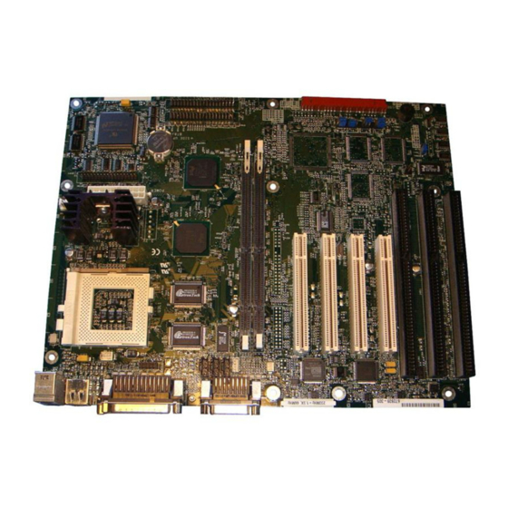
Page 8: Motherboard Components
Optional Brooktree Bt829A video capture processor † Optional ATI-ImpacTV NTSC/PAL TV-out encoder † Optional VESA /ATI Multimedia Channel connector Other features Plug and Play compatible Support for Advanced Power Management Software drivers and utilities are available from Intel. Sec. Pri. OM06169 Figure 1. Motherboard Components... -
Page 9: Motherboard Manufacturing Options
Motherboard Description Yamaha OPL3-SA3 audio codec Battery Yamaha OPL4-ML component Optional ATI-264GT Rage II+ graphics controller CD-ROM audio connector Optional Brooktree Bt829A video capture processor Line-in audio input connector Front panel header Telephony connector Onboard speaker Back panel I/O connectors GPIO header Serial port 2 header System fan connector... -
Page 10: Form Factor
AN430TX Motherboard Technical Product Specification 1.3 Form Factor The motherboard is designed to fit into a standard ATX form factor chassis. Figure 2 illustrates the form factor for the motherboard. The location of the I/O connectors and mounting holes are in strict compliance with the ATX specification (see Section 5.1). -
Page 11: I/O Shield
Motherboard Description 1.4 I/O Shield The back panel I/O shield for the AN430TX motherboard must meet specific dimensional and material requirements. Computers based on this motherboard need the back panel I/O shield in order to pass certification testing. Figure 3 shows the critical dimensions for the I/O shield and indicates the position of each cutout. -
Page 12: Microprocessor
AN430TX Motherboard Technical Product Specification 1.5 Microprocessor The motherboard supports: Pentium processors operating at 90, 100, 120, 133, 150, 166, and 200 MHz Pentium processors with MMX technology operating at 166, and 200 MHz An onboard voltage regulator derives the necessary voltage from the computer’s power supply and enables use of standard or VRE-specified processors. -
Page 13: Memory
Motherboard Description 1.6 Memory 1.6.1 Main Memory The motherboard has two 168-pin DIMM sockets. Memory can be installed in one or two sockets. Minimum memory size is 8 MB. Maximum memory size is 256 MB. The BIOS automatically detects memory type, size, and speed so no jumper settings are required. The motherboard supports the following: 168-pin 3.3 V DIMMs with tin-plated contacts 60 and 66 MHz bus speeds... -
Page 14: Second Level Cache
EDO DRAM, SDRAM is synchronous with the memory clock. This simplifies the timing design and increases memory speed because all timing is dependent on the number of memory clock cycles. SDRAM DIMM should meet the Intel 4-clock 66 MHz 64-bit unbuffered SDRAM DIMM v1.0 specification. -
Page 15: 82371Ab Pci Isa Ide Xcelerator (Piix4)
Internal clock control (gated off if no host or PCI bus activity) 1.7.2 82371AB PCI ISA IDE Xcelerator (PIIX4) The Intel 82371AB PCI ISA IDE Xcelerator (PIIX4) is a multifunction PCI device implementing a PCI to ISA bridge, PCI IDE functionality, a Universal Serial Bus (USB) host/hub function, and Enhanced Power Management. -
Page 16: Universal Serial Bus (Usb) Support
AN430TX Motherboard Technical Product Specification Real-Time Clock 256 byte battery-backed CMOS SRAM Includes date alarm 16-bit counters/timers based on 82C54 1.7.3 Universal Serial Bus (USB) Support The motherboard features two USB ports. The ports permit the direct connection of two USB peripherals without an external hub. -
Page 17: Super I/O Controller
Motherboard Description NOTE If you connect an LS-120 drive to an IDE connector and configure it as the “A” drive and configure a standard 3.5-inch floppy as a “B” drive, the standard floppy must be connected to the floppy drive cable’s “A” connector (the connector at the end of the cable). 1.8 Super I/O Controller The PC87307VUL Super I/O Controller from National Semiconductor is an ISA Plug and Play compatible (see section 5.1 for compliance level), multifunction I/O device that provides the... -
Page 18: Parallel Port
AN430TX Motherboard Technical Product Specification 1.8.2 Parallel Port The connector for the multimode bidirectional parallel port is a 25-pin D-Sub connector located on the back panel of the motherboard. In the Setup program, there are four options for parallel port operation: Compatible (standard mode) Bidirectional (PS/2-compatible) -
Page 19: Infrared Support
Motherboard Description 1.8.5 Infrared Support † The motherboard has a 6-pin header that supports Hewlett Packard HSDL-1000 compatible infrared (IR) transmitters/receivers. In the Setup program, Serial Port 2 can be directed to a connected IR device. The connection can be used to transfer files to or from portable devices like laptops, PDAs and printers. -
Page 20: Vesa/Ati Multimedia Channel Connector
1.9.1.3 Graphics Drivers and Utilities Graphics drivers and common graphics utilities are available for Windows 3.x, Windows 95, and Windows NT. Drivers and utilities are available from Intel’s World Wide Web site (see Section 5.2). 1.9.2 VESA/ATI Multimedia Channel Connector The motherboard has an optional 40-pin VESA/ATI Multimedia Channel connector that uses 26 pins for the VESA standard bus and 12 pins for the ATI Enhanced Visual Architecture bus. -
Page 21: Impactv Ntsc/Pal Encoder
(SDA) pins. 1.9.3.2 Video Capture Drivers and Utilities Video capture software and utilities are available from Intel’s World Wide Web site (see Section 5.2). 1.9.4 ImpacTV NTSC/PAL Encoder The optional ATI-ImpacTV NTSC/PAL Encoder is an ASIC that provides a TV-out interface for the ATI-264GTB 3D Rage II+ multimedia graphics accelerators. -
Page 22: Audio Subsystem
AN430TX Motherboard Technical Product Specification NOTE A video riser card is required for TV outputs and video capture inputs (shown in Figure 7). 1.10 Audio Subsystem † The onboard audio subsystem features the Yamaha OPL YMF715, a 100-pin SQFP audio chip. It integrates a 16-bit audio codec, OPL3 FM synthesis and its DAC, 3-D enhanced stereo controller, and an interface for MPU-401 and a joystick. -
Page 23: Yamaha Opl4-Ml
Wave synthesis results in richer and more realistic sounds then that of FM synthesis. 1.10.2 Audio Drivers and Utilities Audio software and utilities are available from Intel’s World Wide Web site (see Section 5.2). 1.10.3 Audio Connectors The board has these audio connectors:... -
Page 24: Motherboard Connectors
AN430TX Motherboard Technical Product Specification 1.11 Motherboard Connectors Figure 4 shows the connectors on the motherboard. J2G2 J2G1 J2H3 J2H4 Connectors(4) Telephony J4C1, J4D1 J4E1, J4E2 CD-ROM Line-in ATAPI Audio Audio Audio (Optional) Connectors(3) Serial Port 2 J4A1, J4B1 J4B2 J3F1 J2J1 Video... -
Page 25: Standard Cd-Rom Audio Connector (J2G2)
Motherboard Description Table 2. Standard CD-ROM Audio Connector (J2G2) Signal Name Ground CD audio left channel Ground CD audio right channel Table 3. Optional ATAPI Audio Connector (J2G1) Signal Name CD audio left channel Ground Ground CD audio right channel Table 4. -
Page 26: Cpu Fan Connector (J6M2)
AN430TX Motherboard Technical Product Specification Table 7. CPU Fan Connector (J6M2) Signal Name Ground +12 V No connect Table 8. Floppy Drive Connector (J7L2) Signal Name Signal Name Ground DENSEL Ground Reserved FDEDIN# Ground FDINDX# (Index) Ground FDM00# (Motor enable A) Ground FDDS1# (Drive select B) Ground... -
Page 27: Gpio Header (J9A1)
Motherboard Description Table 10. GPIO Header (J9A1) Signal Name No connect GPIO1_7 Ground GPIO1_2 Ground GPIO1_1 Ground Table 11. PCI IDE Connectors (J9H1, J10H1) Signal Name Signal Name Reset IDE Ground Host data 7 Host data 8 Host data 6 Host data 9 Host data 5 Host data 10... -
Page 28: Optional Vesa/Ati Multimedia Channel Connector (J5F1)
AN430TX Motherboard Technical Product Specification Table 13. Optional VESA/ATI Multimedia Channel Connector (J5F1) Signal Name Signal Name Ground Data 0 Ground Data 1 Ground Data 2 Data enable Data 3 Sync enable Data 4 PCLK enable Data 5 Data 6 Ground Data 7 Ground... -
Page 29: Power Supply Connector
Motherboard Description 1.11.1 Power Supply Connector When used with a power supply that supports remote power on/off, the motherboard can turn off the computer’s power through software control. Pin 14 of the power supply connector lets the motherboard recognize a power supply that supports this “soft-off” feature; the power supply must tie pin 14 to ground. -
Page 30: Front Panel Connectors
AN430TX Motherboard Technical Product Specification 1.11.2 Front panel Connectors The front panel connector includes headers for these I/O connections: Speaker Reset switch Power LED Hard drive activity LED Infrared (IrDA) port Sleep switch Power switch Speaker Reset Pwr LED HD LED Infrared Sleep Pwr On OM06166... -
Page 31: Front Panel I/O Connectors
Motherboard Description Table 16. Front Panel I/O Connectors Signal Name Connector SW_ON# Power On Ground SLEEP Sleep/Resume SLEEP_PU (pullup) No connect none +5 V IrDA IrRX Ground IrTX CONIR (Consumer IR) No connect none HD_PWR +5 V HD LED HD Active# HD_PWR No connect/Key none... - Page 32 AN430TX Motherboard Technical Product Specification Closing the sleep/resume switch generates a system management interrupt (SMI) to the processor, which immediately goes into system management mode (SMM). While the computer is in sleep mode it is fully capable of responding to and servicing external interrupts (such as an incoming fax) even though the monitor turns on only if a keyboard or mouse interrupt occurs.
-
Page 33: Back Panel Connectors
Motherboard Description 1.11.3 Back Panel Connectors Figure 6 shows the location of the back panel I/O connectors, which include: PS/2-style keyboard and mouse connectors Two USB connectors One parallel port One serial port Optional video monitor connector MIDI/game port External audio jacks: Line Out, Line In and Mic In Keyboard Parallel Port MIDI/Game Port... -
Page 34: Ps/2 Keyboard And Mouse Connectors
AN430TX Motherboard Technical Product Specification Table 17. PS/2 Keyboard and Mouse Connectors Signal Name Data No connect Ground +5 V (fused) Clock No connect Table 18. USB Connectors Signal Name Power USBP0# [USBP1#] USBP0 [USBP1] Ground Table 19. Parallel Port Connector Signal Name Signal Name Strobe#... -
Page 35: Optional Vga Video Monitor Connector
Motherboard Description Table 21. Optional VGA Video Monitor Connector Signal Name Signal Name +5 V fused Green Ground Blue No connect No connect Monitor ID 1 Ground Horizontal Sync Ground Vertical Sync Ground Monitor ID 2 Ground Table 22. MIDI / Game Port Connector Signal Name Signal Name Power... -
Page 36: Optional Tv/Video Riser Card Connectors
AN430TX Motherboard Technical Product Specification 1.11.4 Optional TV/Video Riser Card Connectors Figure 7 shows the location of the connectors on the TV/video riser card, which include: S-Video input and output jacks RCA composite video input and output jacks S-Video Output Composite Vi deo Ou tp ut S-V ide o Input Composite Video Input... -
Page 37: Rca Composite Video In Connector
Motherboard Description Table 25. S-Video In and I C Connector Signal Name Ground Ground Y (LUMA In) C (CHROMA In) IICCLK (I C bus clock) +12 V (fused) IICDAT (I C bus data) Table 26. RCA Composite Video In Connector Signal Name 1 (Sleeve) Ground... -
Page 38: Add-In Board Expansion Connectors
AN430TX Motherboard Technical Product Specification 1.12 Add-in Board Expansion Connectors The motherboard contains three PCI slots, two ISA slots and one shared slot (for a PCI or ISA card). The PCI bus supports up to four bus masters through the four PCI connectors (see Section 5.1 for information about compliance with the PCI specification). -
Page 39: Isa Bus Connectors
Motherboard Description Table 28. ISA Bus Connectors Signal Name Signal Name Ground IOCHK# (IOCHCK#) RESET (RESDRV) +5 V IRQ9 -5 V DRQ2 -12 V SRDY# (NOWS#) +12 V Ground IOCHRDY (CHRDY) SMEMW# (SMWTC#) SMEMR# (SMRDC#) SA19 IOW# (IOWC#) SA18 IOR# (IORC#) SA17 DACK3# SA16... - Page 40 AN430TX Motherboard Technical Product Specification Table 28. ISA Bus Connectors (continued) Signal Name Signal Name IRQ11 LA21 IRQ12 LA20 IRQ15 LA19 IRQ14 LA18 DACK0# LA17 DRQ0 MEMR# (MRDC#) DACK5# MEMW# (MWTC#) DRQ5 DACK6# DRQ6 SD10 DACK7# SD11 DRQ7 SD12 +5 V SD13 Master16# (MASTER#) SD14...
-
Page 41: Jumper Settings
Motherboard Description 1.13 Jumper Settings Figure 8 shows the location of jumper blocks on the motherboard. J6M1 STD/ J8A1 Normal/ Recovery J9C1 OM06168 Figure 8. Jumper Locations CAUTION Do not move any of the jumpers with the power on. Always turn off the power and unplug the power cord from the computer before changing jumpers. -
Page 42: Processor Configuration (J9C1-C, D)
AN430TX Motherboard Technical Product Specification Table 29. Jumper Settings Function Jumper Configuration Processor Voltage J6M1 1-2 Standard voltage 2-3 VRE voltage (Default) Password J9C1-A 1-2 Password enabled (Default) 2-3 Password clear/disabled CMOS (NVRAM and ESCD) Clear J9C1-A 4-5 Keep (Default) 5-6 Clear BIOS Setup Access J9C1-B... -
Page 43: Password Clear (J9C1-A)
Motherboard Description 1.13.2 Password Clear (J9C1-A) Use this jumper to clear the password if the password is forgotten. The default setting is pins 1 -2 (password enabled). To clear the password, turn off the computer, move the jumper to pins 2-3, and turn on the computer. -
Page 44: Environmental
AN430TX Motherboard Technical Product Specification 1.15 Environmental Table 31. Motherboard Environmental Specifications Parameter Specification Temperature Non-Operating C to +70 Operating C to +55 Vibration Unpackaged 5 Hz to 20 Hz : 0.01g² Hz sloping up to 0.02 g² Hz 20 Hz to 500 Hz : 0.02g² Hz (flat) Packaged 10 Hz to 40 Hz : 0.015g²... -
Page 45: Power Supply Considerations
Motherboard Description 1.16.1 Power Supply Considerations The motherboard is designed to operate with at least a 200 W ATX power supply for typical configurations or a higher wattage supply for heavily loaded configurations. The power supply must meet the following requirements: Rise time for power supply: 2 ms to 20 ms Minimum delay for Reset to Power Good: 100 ms Minimum Powerdown warning: 1 ms... -
Page 46: Emi
AN430TX Motherboard Technical Product Specification 1.17.2 EMI 1.17.2.1 FCC Class B Title 47 of the Code of Federal Regulations, Parts 2 & 15, Subpart B, pertaining to unintentional radiators. (USA) 1.17.2.2 CISPR 22, 2nd Edition, 1993 Limits and methods of measurement of Radio Interference Characteristics of Information Technology Equipment. -
Page 47: Motherboard Resources
2 Motherboard Resources NOTE For more detailed information about the resources used for onboard audio, see the Audio Subsystem section in Chapter 1. 2.1 Memory Map Table 34. Memory Map Address Range Address Range (decimal) (hex) Size Description 1024 K - 262144 K 100000 - 10000000 255 MB Extended Memory... -
Page 48: I/O Map
AN430TX Motherboard Technical Product Specification 2.3 I/O Map Table 36. I/O Map Address (hex) Size Description 0000 - 000F 16 bytes PIIX4 - DMA 1 0020 - 0021 2 bytes PIIX4 - Interrupt Controller 1 002E - 002F 2 bytes Super I/O Controller Configuration Registers 0040 - 0043 4 bytes... - Page 49 Motherboard Resources Table 36. I/O Map (continued) Address (hex) Size Description 03B4 - 03B5 2 bytes Video (VGA) 03BA 1 byte Video (VGA) 03BC - 03BF 4 bytes LPT3 03C0 - 03CA 11 bytes Video (VGA) 03CC 1 byte Video (VGA) 03CE - 03CF 2 bytes Video (VGA)
-
Page 50: Pci Configuration Space Map
Number (hex) Description Intel 82430TX (MTXC) Intel 82430TX (PIIX4 ) PCI/ISA bridge, function 0 Intel 82430TX (PIIX4 ) IDE Bus Master, function 1 Intel 82430TX (PIIX4 ) USB, function 2 Intel 82430TX (PIIX4) Power Management, function 3 ATI VGA Graphics... -
Page 51: Pci Interrupt Routing Map
Motherboard Resources 2.6 PCI Interrupt Routing Map The PCI specification allows for sharing of interrupts between devices attached to the PCI bus. In most cases, the small amount of latency added by interrupt sharing does not affect the normal operation or throughput of the devices. However, in some special cases where maximum performance is needed from a device, you may want to ensure that it does not share an interrupt with other PCI devices. - Page 52 AN430TX Motherboard Technical Product Specification Now, however, plug an add-in card that has one interrupt (group INTA) into the first PCI slot. Plug a second add-in card that has two interrupts (groups INTA and INTB) into the second PCI slot. INTA in the first slot is connected to signal PIRQA. INTA in the second slot is connected to signal PIRQB, and INTB is connected to signal PIRQC.
-
Page 53: Bios And Setup Program
3.1.1 BIOS Flash Memory Organization The Intel PA28FB200BX 2 Mbit Flash component is organized as 256K x 8 (256 KB). The Flash device is divided into areas as described in Table 40. The table shows the addresses in the ROM image in normal mode (the addresses change in BIOS Recovery Mode). -
Page 54: Bios Upgrades
For information about the version of PCI and Plug and Play supported by this BIOS, see Section 5.1. You can obtain copies of the specifications from the Intel World Wide Web site (see Section 5.2). Peer-to-peer hierarchical PCI Bridge is supported, and by using an OEM-supplied option ROM or TSR, a PCI-to-PCMCIA bridge capability is possible as well. -
Page 55: Isa Plug And Play
The BIOS support for DMI enables the maximum benefit from applications such as LANDesk Client Manager from Intel. The BIOS stores and can report on the following types of DMI information: BIOS data, such as the BIOS revision level Fixed information, such as data about the motherboard, peripherals, serial numbers and asset tags, etc. -
Page 56: Advanced Power Management
Flash memory, so the BIOS can also report that information. Once this information is written, it is locked (read-only). Intel can provide a utility for making DMI calls to the BIOS. The latest DMI specification is available from Intel (see Section 5.2) and other sites. -
Page 57: Boot Options
E8000-E8FFF. You can use this area to display a custom OEM logo during POST, or can insert a binary image that executes at certain times during the POST. A utility is available from Intel to assist with installing a logo into Flash for display during POST. -
Page 58: Recovering Bios Data
To create a BIOS recovery diskette, you must make a bootable DOS diskette and place the recovery files on it. The recovery files are available from Intel. To recover the BIOS, turn off the computer and move the jumper to the BIOS recovery setting. -
Page 59: Main Menu
BIOS and Setup Program Table 42. Overview of the Setup Menu Screens Setup Menu Screen Description Main Set up and modify some of the basic options of a PC, such as time, date, diskette drives, and hard drives. Advanced Modify the more advanced features of a PC, such as peripheral configuration and advanced chipset configuration. - Page 60 AN430TX Motherboard Technical Product Specification 3.2.2.6 Language Selects the current default language used by the BIOS. The options are: English (US) (default) Italiano Français Deutsch Español 3.2.2.7 System Time Specifies the current time. 3.2.2.8 System Date Specifies the current date. Select the month, day, and year from a pop-up menu. 3.2.2.9 Floppy Options Submenu When selected, this is used to configure the diskette drives.
-
Page 61: Primary/Secondary Ide Master/Slave Configuration Submenus
BIOS and Setup Program 3.2.2.10 Primary IDE Master Reports size of a connected IDE device. When selected, this displays the device configuration subscreen for the Primary IDE master interface. 3.2.2.11 Primary IDE Slave Reports size of a connected IDE device. When selected, this displays the device configuration subscreen for the Primary IDE slave interface. - Page 62 AN430TX Motherboard Technical Product Specification 3.2.3.4 Sectors If device configuration is set to Auto, this field reports the number of sectors for your hard disk and cannot be modified. If IDE Device Configuration is set to User Definable, you must type the correct number of sectors for your hard disk.
-
Page 63: Advanced Menu
BIOS and Setup Program 3.2.3.10 Ultra DMA Sets the Ultra DMA mode for the hard disk drive. The options are: Disabled (default) Mode 0 Mode 1 Mode 2 3.2.4 Advanced Menu 3.2.4.1 Plug & Play O/S Select Yes if a Plug and Play operating system is being used. The options are: Yes (default) 3.2.4.2 Reset Configuration Data... - Page 64 AN430TX Motherboard Technical Product Specification 3.2.4.6.2 IRQ Reservation Reserve specific IRQs for use by legacy ISA devices. The options are: IRQ3 Available | Reserved IRQ4 Available | Reserved IRQ5 Available | Reserved IRQ7 Available | Reserved IRQ9 Available | Reserved IRQ10 Available | Reserved IRQ11...
- Page 65 BIOS and Setup Program 3.2.4.7.5 Mode Selects the mode for the parallel port. The options are: † Output only (operates in AT -compatible mode) Bi-directional (operates in bidirectional PS/2-compatible mode) (default) EPP (Extended Parallel Port, a high-speed bidirectional mode) ECP (Enhanced Capabilities, a high-speed bidirectional mode) 3.2.4.7.6 Floppy disk controller Configures the floppy disk controller.
- Page 66 AN430TX Motherboard Technical Product Specification 3.2.4.8.3 Keyboard Auto-repeat Rate Selects the key repeat rate. The options are: 30/sec (default) 26.7/sec 21.8/sec 18.5/sec 13.3/sec 10/sec 6/sec 2/sec 3.2.4.8.4 Keyboard Auto-repeat Delay Selects the delay before key repeat. The options are: ¼ sec ½...
-
Page 67: Security Menu
BIOS and Setup Program 3.2.4.10 DMI Event Logging Sub-menu 3.2.4.10.1 Event Log Capacity Indicates if there is space available in the event log. There are no options. 3.2.4.10.2 Event Log Validity Indicates if the contents of the event log are valid. There are no options. 3.2.4.10.3 View DMI event log Enables viewing of DMI event log. -
Page 68: Power Menu
AN430TX Motherboard Technical Product Specification 3.2.5.5 Unattended Start When enabled, the computer will boot; however, if the computer is password protected, the keyboard will be locked. Enter the user password to unlock the computer. The user password is also required to boot from the floppy drive. The options are: Disabled (default) Enabled 3.2.6 Power Menu... - Page 69 BIOS and Setup Program 3.2.7.2 First Boot Device This status field reports the category of bootable device. The options are one (and only one) of the following: Removable devices Hard Drive ATAPI CD-ROM devices Network boot 3.2.7.3 Second Boot Device This status field reports the category of bootable device.
-
Page 70: Exit Menu
AN430TX Motherboard Technical Product Specification 3.2.7.7 Removable Devices This screen lists the available removable devices. The operating system assigns drive letters to these devices in the order listed. You may change the sequence and therefore the drive lettering for these devices by pressing the <+> or <-> keys. The options are any available removable devices. -
Page 71: Error Messages
4 Error Messages 4.1 BIOS Error Messages Table 43. BIOS Error Messages Error Message Explanation Diskette drive A error or Drive A: or B: is present but fails the BIOS POST diskette tests. Diskette drive B error Check to see that the drive is defined with the proper diskette type in Setup and that the diskette drive is attached correctly. -
Page 72: Port 80H Post Codes
AN430TX Motherboard Technical Product Specification Table 43. BIOS Error Messages (continued) Error Message Explanation Previous boot incomplete - Default Previous POST did not complete successfully. POST loads default configuration used values and offers to run Setup. If the failure was caused by incorrect values and they are not corrected, the next boot will likely fail. -
Page 73: Port 80H Codes
Error Messages Table 44. Port 80h Codes Code Description of POST Operation Currently In Progress Verify Real Mode Disable Non-Maskable Interrupt (NMI) Get CPU type Initialize system hardware Initialize chipset with initial POST values Set IN POST flag Initialize CPU registers Enable CPU cache Initialize caches to initial POST values Initialize I/O component... - Page 74 AN430TX Motherboard Technical Product Specification Table 44. Port 80h Codes (continued) Code Description of POST Operation Currently In Progress Shadow system BIOS ROM Reinitialize the cache (MB only) Autosize cache Configure advanced chipset registers Load alternate registers with CMOS values Set Initial CPU speed new Initialize interrupt vectors Initialize BIOS interrupts...
- Page 75 Error Messages Table 44. Port 80h Codes (continued) Code Description of POST Operation Currently In Progress Display error messages Check for configuration errors Test real-time clock Check for keyboard errors Test for key lock on Set up hardware interrupt vectors Initialize coprocessor if present Disable onboard Super I/O ports and IRQs Late POST device initialization...
- Page 76 AN430TX Motherboard Technical Product Specification Table 44. Port 80h Codes (continued) Code Description of POST Operation Currently In Progress Erase F2 prompt Scan for F2 key stroke Enter SETUP Clear IN POST flag Check for errors POST done - prepare to boot operating system One short beep before boot Terminate QuietBoot Check password (optional)
- Page 77 Error Messages Table 44. Port 80h Codes (continued) Code Description of POST Operation Currently In Progress Shadow Boot Block System memory test Initialize interrupt vectors Initialize Run Time Clock Initialize video Initialize beeper Initialize boot Clear Huge segment Boot to Mini DOS Boot to Full DOS...
-
Page 79: Specifications And Online Support
Version 2, Revision 0, April 9, 1996 Video Electronics Standards Association Desktop Management Interface Version 2.0, October 16, 1995 BIOS specification American Megatrends Inc., Award Software International Inc., Dell Computer Corporation, Intel, Phoenix Technologies Ltd, SystemSoft Corporation DPMS Display Power Management Revision 1.0 Signaling Video Electronics Standards Association “El Torito”... -
Page 80: Online Support
AN430TX Motherboard Technical Product Specification 5.2 Online Support Find information about Intel motherboards under “Product Info” or “Customer Support” at this World Wide Web site: http://www.intel.com/ or at this FTP site: ftp://ftp.intel.com/pub/bios/... - Page 81 Index 116450, 17 16550A, 17 FCC compliance, 46 Feature Connector, 79 AMI Megakey, 18 floppy drive controller, 18 APM, 79 form factor, 79 ATA-33, 79 FTP site, 80 ATI TractorBeam, 21 ATI-264GT Rage II+, 19 ATX, 79 graphics controller, 19 heat sink, clips for, 12 hot key, 18 battery, 18...
- Page 82 AN430TX Motherboard Technical Product Specification sharing interrupts, 51 slots for add-in cards, 38 parallel port, 18 specifications, 79 PC87307VUL, 17 Super I/O controller, 17 PCI, 79 S-Video, 21 bus connectors, 38 S-video connector, 36, 37 bus interface, 15 expansion slots, 51 interrupt sharing, 51 PIIX4, 51 TractorBeam, 21...