Table of Contents
Advertisement
Quick Links
M/B For Socket-A Athlon/Duron Processor
Trademark:
*
Specifications and Information contained in this documentation are furnished for information use only, and are
subject to change at any time without notice, and should not be construed as a commitment by manufacturer.
Polaris 400
USER'S MANUAL
NO. G03-V400MAX1A
Release date: October 2002
Advertisement
Table of Contents

Related Manuals for JETWAY POLARIS400


Summary of Contents for JETWAY POLARIS400
- Page 1 Polaris 400 USER'S MANUAL M/B For Socket-A Athlon/Duron Processor NO. G03-V400MAX1A Release date: October 2002 Trademark: Specifications and Information contained in this documentation are furnished for information use only, and are subject to change at any time without notice, and should not be construed as a commitment by manufacturer.
-
Page 2: Table Of Contents
TABLE OF CONTENT USER’S NOTICE........................... 1 MANUAL REVISION INFORMATION..................1 COOLING SOLUTIONS ......................1 CHAPTER 1 INTRODUCTION OF Polaris 400 MOTHERBOARD FEATURE OF MOTHERBOARD ..................2 SPECIFICATION........................3 PERFORMANCE LIST ......................4 LAYOUT DIAGRAM & JUMPER SETTING ..............5 CHAPTER 2 HARDWARE INSTALLATION HARDWARE INSTALLATION STEPS ................ -
Page 3: User's Notice
USER’S NOTICE COPYRIGHT OF THIS MANUAL BELONGS TO MANUFACTURER. NO PART OF THIS MANUAL, INCLUDING THE PRODUCTS AND SOFTWARE DESCRIBED IN IT MAY BE REPRODUCED, TRANSMITTED OR TRANSLATED INTO ANY LANGUAGE IN ANY FORM OR BY ANY MEANS WITHOUT WRITTEN PERMISSION OF MANUFACTURER. -
Page 4: Chapter 1 Introduction Of Polaris 400 Motherboard
Chapter 1 Introduction of Polaris 400 Motherboard 1-1 Feature of motherboard The Polaris 400 motherboard is design for use AMD Athlon/Duron/Athlon XP 200MHz /266MHz/333MHz (Double Data Rate) Front Side Bus Frequency CPU, which utilize the Socket-A design and the memory size expandable to 3.0GB. This motherboard use the newest VIA KT400 chipset, whose 133MHz/266MHz /333MHz (Double Data Rate) Front Side Bus frequency and 400MHz memory interface delivers a clear upgrade path to the future generation of 266MHz/333MHz processors and DDR266... -
Page 5: Specification
1-2 Specification Spec Description ∗ ATX form factor 4 layers PCB size: 30.5x24.5cm Design ∗ VIA KT400/VT8235 Chipset Chipset ∗ Support AMD Athlon 1.1GHz∼1.4GHz processor CPU Socket ∗ Support AMD Duron 900MHz∼1.3GHz processor ∗ Support AMD Athlon XP1500+~XP2700+ processor ∗ Support 200MHz/266MHz/333MHz (Double Data Rate) Front Side Bus frequency processors ∗... -
Page 6: Performance List
1-3 Performance List The following performance data list is the testing result of some popular benchmark testing programs. These data are just referred by users, and there is no responsibility for different testing data values gotten by users (the different Hardware & Software configuration will result in different benchmark testing results.) Performance Test Report CPU:... -
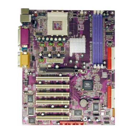
Page 7: Layout Diagram & Jumper Setting
1-4 Layout Diagram & Jumper Setting PRINT GAME/MIDI PORT PS/2 Mouse PS/2 Keyboard COM1 COM2 LINE-IN LINE-OUT K/B Power ON Jumper (JP1) CPU Socket PS2 KB/Mouse Port CPU FAN USB Port /LAN Connector DDR DIMM X3 PC99 Back Panel VIA KT400 Chip ATA 100 IDE Conn. - Page 8 Jumper Name Description Page Keyboard Power On Enable/Disabled 3-pin Block USB Wake-Up Enable/Disabled 3-pin Block CPU Front Side Bus Frequency 4-pin Block Keyboard Password Clear jumper 3-pin Block JBAT CMOS RAM Clear jumper 3-pin Block Connectors Connector Name Description Page ATXPOW ATX Power Connector 20-pin Block...
-
Page 9: Chapter 2 Hardware Installation
Hardware installation 2-1 Hardware installation Steps Before using your computer, you had better complete the following steps: 1. Check motherboard setting 2. Install CPU 3. Install Memory 4. Install Expansion cards 5. Connect Ribbon cables, Panel wires, and power supply 6. -
Page 10: Install Cpu
1-2 closed Normal 2-3 closed Keyboard Password Clear Keyboard Password Clear Jumper Setting CMOS RAM Clear (3-pin) : JBAT A battery must be used to retain the motherboard configuration in CMOS RAM short 1-2 pins of JBAT to store the CMOS data. To clear the CMOS, follow the procedure below: Turn off the system and unplug the AC power Remove ATX power cable from ATX power connector... -
Page 11: About Amd Athlon & Duron 462-Pin Cpu
Serial Port - a low speed interface typically used for mouse and external modems. Parallel Port - a low speed interface typically used for printers. PS/2 - a low speed interface used for mouse and keyboards. USB - Universal Serial Bus - a medium speed interface typically used for mouse, keyboards, scanners, and some digital cameras. -
Page 12: Install Memory
Socket-A Colden Arrow CPU ZIF Socket-A When you put the CPU into the ZIF socket. No force require to insert of the CPU, then press the level to Locate position slightly without any extra force. 2-4 Install Memory This motherboard provides three 184-pin DUAL INLINE MEMORY MODULES (DIMM) sites for memory expansion available from minimum memory size of 64MB to maximum memory size of 3.0GB DDR SDRAM. -
Page 13: Expansion Card
WARNING! For the DDR SDRAM CLOCK is set at 166MHz, use only DDR333 compliant DDR Modules. When this motherboard operate at 133Mhz, most system will not even boot if non-compliant modules are used because of the strict timing issues, if your DDR Modules are not DDR266-compliant, set the DDR SDRAM clock to 100MHz to ensure system stability. -
Page 14: Interrupt Request Table For This Motherboard
Interrupt request are shared as shown the table below: INT A INT B INT C INT D PCI slot 1 Shared PCI slot 2 Shared PCI slot 3 Shared ... - Page 15 ROW2 ROW1 3.3V 3.3V -12V 3.3V Soft Power On Power OK +5V (for Soft Logic) +12V Pin 1 PS/2 Mouse & PS/2 Keyboard Connector: J1(KB/MS) The connectors for PS/2 keyboard and PS/2 Mouse. USB Port connector: USB The connectors are 4-pin connector that connect USB devices to the system board. LAN Port connector: LAN The connector is standard RJ45 connector for network connection Parallel Port Connector (25-pin female): PARALL...
- Page 16 Pin 1 Floppy Drive Connector Primary IDE Connector (40-pin block): IDE1 This connector supports the provided IDE hard disk ribbon cable. After connecting the single plug end to motherboard, connect the two plugs at other end to your hard disk(s). If you install two hard disks, you must configure the second drive to Slave mode by setting its jumpers accordingly.
-
Page 17: Headers
This connector support the provided Serial ATA IDE cable for connect the Serial ATA hard disk. Pin 1 SATA2 SATA1 Serial-ATA Port Connector 2-6-2 Headers Line-Out, MIC Header (9-pin): AUDIO This header connect to Front Panel Line-out, MIC connector with cable. AUDIO AUD - FPO UT - L AUD - RET - L... - Page 18 1394 Port Headers (9-pin): 1394A, 1394B 1394A 1394B Pin 1 Pin 1 1394 Port Headers IDE Activity LED: HD LED This connector connects to the hard disk activity indicator light on the case. Reset switch lead: RESET This 2-pin connector connects to the case-mounted reset switch for rebooting your computer without having to turn off your power switch.
- Page 19 (10) FAN Speed Headers (3-pin) : FAN1, FAN2, CPUFAN These connectors support cooling fans of 350mA (4.2 Watts) or less, depending on the fan manufacturer, the wire and plug may be different. The red wire should be positive, while the black should be ground. Connect the fan’s plug to the board taking into consideration the polarity of connector.
-
Page 20: Starting Up Your Computer
2-7 Starting Up Your Computer 1. After all connection are made, close your computer case cover. 2. Be sure all the switch are off, and check that the power supply input voltage is set to proper position, usually in-put voltage is 220V∼240V or 110V∼120V depending on your country’s voltage used. -
Page 21: Chapter 3 Introducing Bios
Chapter 3 Introducing BIOS The BIOS is a program located on a Flash Memory on the motherboard. This program is a bridge between motherboard and operating system. When you start the computer, the BIOS program gain control. The BIOS first operates an auto-diagnostic test called POST (power on self test) for all the necessary hardware, it detects the entire hardware device and configures the parameters of the hardware synchronization. -
Page 22: The Main Menu
3-3 The Main Menu Once you enter Award BIOS CMOS Setup Utility, the Main Menu (Figure 3-1) will appear on the screen. The Main Menu allows you to select from fourteen setup functions and two exit choices. Use arrow keys to select among the items and press <Enter> to accept or enter the sub-menu. -
Page 23: Standard Cmos Features
Load Optimized Defaults Use this menu to load the BIOS default values that are factory settings for optimal performances system operations. Load Standard Defaults Use this menu to load the BIOS default values for the minimal/stable performance system operation. Set Supervisor/User Password Use this menu to set User and Supervisor Passwords. -
Page 24: Advanced Bios Features
The time format is <hour><minute><second>. Primary Master/Primary Slave Secondary Master/Secondary Slave Press PgUp/<+> or PgDn/<–> to select Manual, None, Auto type. Note that the specifications of your drive must match with the drive table. The hard disk will not work properly if you enter improper information for this category. - Page 25 Allows you to choose the VIRUS Warning feature for IDE Hard Disk boot sector protection. If this function is enabled and someone attempt to write data into this area, BIOS will show a warning message on screen and alarm beep. Disabled (default) No warning message to appear when anything attempts to access the boot sector or hard disk partition table.
-
Page 26: Advanced Chipset Features
Sets the number of times a second to repeat a keystroke when you hold the key down. The settings are: 6, 8, 10, 12, 15, 20, 24, and 30. Typematic Delay (Msec) Sets the delay time after the key is held down before is begins to repeat the keystroke. The settings are 250, 500, 750, and 1000. -
Page 27: Dram Timing Settings
Selecting Enabled allows caching of the system BIOS ROM at F0000h-FFFFFh, resulting in better system performance. However, if any program writes to this memory area, a system error may result. The settings are: Enabled and Disabled. Video RAM Cacheable Select Enabled allows caching of the video BIOS, resulting in better system performance. However, if any program writes to this memory area, a system error may result. -
Page 28: Agp Timing Settings
CMOS Setup Utility – Copyright(C) 1984-2002 Award Software AGP Timing Settings AGP Transfer Aperture Size Item Help AGP Transfer Mode Auto AGP Driving Control Auto AGP Driving Value Menu Level >> AGP Fast Write Disabled AGP Master 1 WS Write Enabled AGP Master 1 WS Read Enabled... -
Page 29: Integrated Peripherals
CMOS Setup Utility – Copyright(C) 1984-2002 Award Software Integrated Peripherals > OnChip IDE Function Press Enter Item Help > OnChip Device Function Press Enter > Onboard Super IO Function Press Enter Init Display First PCI Slot Menu Level > ↑↓→← Move Enter:Select +/-/PU/PD:Value F10:Save ESC:Exit F1:General Help F5:Previous Values F6:Optimized Defaults... -
Page 30: Onchip Device Function
The integrated peripheral controller contains an IDE interface with support for two IDE channels. Select Enabled to activate each channel separately. The settings are: Enabled and Disabled. Primary/Secondary Master/Slave PIO The four IDE PIO (Programmed Input/Output) fields let you set a PIO mode (0-4) for each of the four IDE devices that the onboard IDE interface supports. -
Page 31: Onchip Super Io Function
CMOS Setup Utility – Copyright(C) 1984-2002 Award Software Onboard Super IO Function Onboard FDD Controller Enabled Item Help Onboard Serial Port 1 3F8/IRQ4 Onboard Serial Port 2 2F8/IRQ3 UART2 Mode Normal Menu Level >> RxD, TxD Active Hi, Lo IR Duplex Mode Half Use IR Pins IRRX/IRTX... -
Page 32: Power Management Setup
The Power Management Setup allows you to configure your system to most effectively save energy saving while operating in a manner consistent with your own style of computer use. CMOS Setup Utility – Copyright(C) 1984-2002 Award Software Power Management Setup ACPI Function Enabled Item Help... -
Page 33: Wake Up Events
CMOS Setup Utility – Copyright(C) 1984-2002 Award Software Wake Up Events Item Help LPT & COM LPT/COM HDD & FDD PCI Master Menu Level >> Wake-Up on LAN/Ring Disabled Wake-Up on PCI PME Disabled Wake-Up On Hot Key (PS2 KB) Disabled RTC Alarm Resume Disabled... -
Page 34: Pnp/Pci Configuration Setup
This section describes configuring the PCI bus system. PCI, or Personal Computer Interconnect, is a system which allows I/O devices to operate at speeds nearing the speed the CPU itself uses when communicating with its own special components. This section covers some very technical items and it is strongly recommended that only experienced users should make any changes to the default settings. -
Page 35: Irq Resources
CMOS Setup Utility – Copyright(C) 1984-2002 Award Software IRQ Resources IRQ3 assigned to PCI Device Item Help IRQ4 assigned to PCI Device IRQ5 assigned to PCI Device IRQ7 assigned to PCI Device Menu Level >> IRQ9 assigned to PCI Device IRQ10 assigned to PCI Device... -
Page 36: Miscellaneous Control
This section is for setting CPU Frequency/Voltage Control. CMOS Setup Utility – Copyright(C) 1984-2002 Award Software Miscellaneous Control Auto Detect DIMM/PCI Clk Enabled Item Help Spread Spectrum Disabled ** Current Host Clock is Host Clock at Next Boot is 100MHz Menu Level >... -
Page 37: Load Standard/Optimized Defaults
Load Standard Defaults When you press <Enter> on this item, you get confirmation dialog box with a message similar Load Standard Defaults (Y/N)? N Pressing <Y> loads the BIOS default values for the most stable, minimal-performance system operations. Load Optimized Defaults When you press <Enter>... -
Page 38: Magic Install Supports Windows 9X/Nt/2K/Xp
Check your package and there is A MAGIC INSTALL CD included. This CD consists of all DRIVERS you need and some free application programs and utility programs. In addition, this CD also include an auto detect software which can tell you which hardware is installed, and which DRIVERS needed so that your system can function properly. -
Page 39: Install Via Service Pack 4 In 1 Driver
AGPVXD : VIA AGPVXD DRIVER IS TO BE INSTALLED, IF YOU ARE USING AN AGP VGA CARD, VIAGART.VXD WILL PROVIDE SERVICE ROUTINES TO YOUR VGA DRIVER AND INTERFACE DIRECTLY TO HARDWARE, PROVIDING FAST GRAPHIC ACCESS IRQ ROUTING : VIA PCI IRQ MINIPORT DRIVER IS TO BE INSTALLED UNDER WIN98 ONLY, IT WILL FIX PCI IRQ ROUTING SEQUENCE INF : VIA REGISTRY DRIVER IS TO BE INSTALLED UNDER WINDOWS... -
Page 40: Sound Install Cmi/C3Dx Pci Audio Codec Driver
5. Click NEXT to Install ATAPI Vender 6. Click NEXT to choose enabled DMA Mode Support Driver 7. Click NEXT to Install VIA AGP VXD Driver 8. Click NEXT to Install VIA IRQ Routing Mini port Driver 9. Click Finish to restart computer 4-2 SOUND Install CMI8738/C3DX PCI Audio Driver 1. - Page 41 3. Choose Setup Language and Click OK 4. Click Next when copyright Issue appears, click Next or choose BROWSE to change the path for the file to be store 5. Enter Program folders name or click Next 6. OS can Auto Find C-Media CMI8738/C3DX PCI Audio Device 7.
-
Page 42: Lan Install Rtl8100 Lan Controller Driver
11. Select C-Media Mixer\Advanced\Speakers , 12. Enable USING Xear 3D, you can select 4/6 this is C-Media Audio speaker Configuration Speakers Xear Function setting . (S/PDIF only support 2 CH speaker output) 13. Select C-Media Mixer\Advanced\volume, this 14. Select C-Media Mixer\Advanced\Sound is 6CH speaker volume Setting Effect . -
Page 43: Sata Install Promise Ata Ide Controller Driver
4-4 SATA Install Promise ATA IDE Controller Driver 1. Click SATA in MAGIC INSTALL MENU 2. Install PROMISE SERIAL ATA Controller Driver 3. Click Yes to Restart your computer after Driver Install Finish The path of the file: For Windows 9X is X:\SATA375\WIN98-ME (including Win95/98/ME) For Windows NT4.0 is X:\SATA375\NT4 For Windows 2000 is X:\SATA375\WIN2000 For Windows XP is X:\SATA375\WINXP... -
Page 44: Magic Bios Install Bios Live Update Utility
appears Setup Window appears 3. Click the Button to start installation 4. Select Program Group name or enter a new group name, click continue to setup and click OK after setup complete 4-5-1 How To Utilize PC-HEALTH Click Program → Winbond Hardware Doctor 2. - Page 45 3. After finish Setup you will have a Magic Double click the Magic BIOS icon you will BIOS icon in your screen have this picture, choose from internet you can upgrade BIOS On-line When On-line update BIOS the program Click Next if you need update BIOS, after will auto-check your BIOS version upgrade BIOS, the system will clear CMOS and automatically restart...
-
Page 46: Pc-Cillin Install Pc-Cillin2002 Anti-Virus Program
4-7 PC-CILLIN Install PC-CILLIN 2002 Anti-virus program 1. Click PC-CILLIN when MAGIC INSTALL 2. (1) Click "Install PC-CILLIN" when PC- MENU appear CILLIN 2002 main menu appears, and Click NEXT when "Install Shield Wizard For PC- CILLIN 2002" (2) Click Open Manual. you can learn PC- CILLIN 2002 how to use 3. -
Page 47: Usb
7. After PC-CILLIN 2002 complete, Please 8. finish register process, we recommend select register your information and get LICENSE update item ro download newest engine code KEY from TREND MICRO web site, enter and virus code your license key and click FINISH Note : Please install ACROBAT READER, Before you read PC-CILLIN 2002 User Manual, the path at X:\acrobat\ar500eng.exe... -
Page 48: How To Update Bios
5. Check device working properly in Device Manager The Path of the file is X:\VIA\VIAUSB20\SETUP.EXE 4-9 HOW TO UPDATE BIOS Before update BIOS please choose Disabled in “Flash Part Write Protect” item on “Miscellaneous Control” in BIOS Setup, please refer page Method 1.