Asko 1325 Installation Instructions Manual
Hide thumbs
Also See for 1325:
- How to use manual (16 pages) ,
- Uso y cuidado (12 pages) ,
- Manuel d’utilisation et d’entretien (12 pages)
Table of Contents
Advertisement
ASKO
A A A A A UT
UT
UT
OMA
OMA
TIC HIGH L
TIC HIGH L
UTOMA
UT
OMATIC HIGH L
OMA
TIC HIGH LOOP
TIC HIGH L
T T T T T he dr
he dr
he dr
ain hose is f
ain hose is f
he dr
he drain hose is f
ain hose is fastened to the
ain hose is f
back of the machine at the best
back of the machine at the best
back of the machine at the best
back of the machine at the best
back of the machine at the best
high loop height.
high loop height.
high loop height. T T T T T o elimina
high loop height.
high loop height.
potential dr
potential drain pr
potential dr
ain pr
ain prob
ain pr
potential dr
potential dr
ain pr
this hose in place.
this hose in place.
this hose in place.
this hose in place.
this hose in place.
CONTENTS
CONTENTS
CONTENTS
CONTENTS
CONTENTS
SAVE THESE INSTRUCTIONS FOR FUTURE REFERENCE
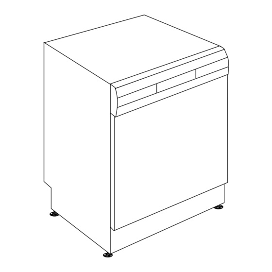
DISHWASHER
INSTALLATION
INSTRUCTIONS
OOP
OOP
OOP
OOP
astened to the
astened to the
astened to the
astened to the
o eliminate
o elimina
o elimina
o elimina
te
te
te
te
oblems
ob
ob
lems, , , , , lea
lems
lems
lea
leav v v v v e e e e e
lea
ob
lems
lea
2
2
3
3
4
5
6
6
7
7
8
8
8
9
9
9
10
12
Page 1
Advertisement
Table of Contents

Related Manuals for Asko 1325

Summary of Contents for Asko 1325
-
Page 1: Table Of Contents
ASKO DISHWASHER INSTALLATION INSTRUCTIONS A A A A A UT TIC HIGH L TIC HIGH L UTOMA OMATIC HIGH L TIC HIGH L TIC HIGH LOOP T T T T T he dr he dr he dr ain hose is f... -
Page 2: Introduction
NOTE: Cosmetic damage must be reported to the ASKO dealer within five days from the date of purchase. If a dishwasher is being installed in this area for the After unpacking the dishwasher, thoroughly check the first time, most of the cabinet work, plumbing, and unit for cosmetic damage. -
Page 3: Dimensions
Rear Tip Guards opening. When using European standard installation, a (P/N 8070851) kick plate is available from your ASKO dealer. (Part Numbers: White=8057528-0; Black=8057528-29) The electrical and water supplies should enter through We recommend that you install tip the area indicated by the shading on the illustration guards when it isn’t possible to fasten... -
Page 4: Hot Water Supply
CORNER INST CORNER INST CORNER INST CORNER INST CORNER INSTALLA ALLA ALLA ALLATION ALLA TION TION TION TION If the dishwasher is installed in a corner, there must be a minimum clearance of 2 inches (50 mm) from the side wall so the door can open. 2”... -
Page 5: Drain Supply
If additional drain hose is needed, please purchase an additional ASKO drain hose and joint it to the provided hose with a 7/8” copper tube. A.) Typical connection to sink plumbing before... -
Page 6: Electrical Connections
ANEL ANEL ANEL All ASKO dishwashers (except Models 1805FI and 1895) have color-coded fill strips to finish off the installation. To remove the access panel, first remove the two screws To prevent damage to the machine, be sure to remove on each side of the access panel. -
Page 7: Moving The Machine Into Place
REMO REMO REMOVING REMO REMO VING VING VING VING THE GU THE GU THE GU THE GU THE GUARD PLA ARD PLA ARD PLA ARD PLATE ARD PLA There are four screws that hold the guard plate in place, After the screws are removed, grip the bottom of the two on the upper/underneath side and two on the front. -
Page 8: Connecting The Water Supply
CONNECTING CONNECTING CONNECTING THE CONNECTING CONNECTING THE W W W W W A A A A A TER SUPPL TER SUPPL TER SUPPL TER SUPPL TER SUPPLY Y Y Y Y In order to prevent heat damage to the inlet valve, all solder connections must be made before the water line is connected to the dishwasher. -
Page 9: Replacing The Toe Kick Brackets
REPLA REPLA REPLACING REPLA REPLA CING CING CING CING THE THE T T T T T OE KICK BRA OE KICK BRA OE KICK BRA OE KICK BRACKETS OE KICK BRA CKETS CKETS CKETS CKETS Adjusting the Bracket Depth Adjusting the Bracket Depth Adjusting the Bracket Depth Adjusting the Bracket Depth Adjusting the Bracket Depth... -
Page 10: Fitting The 1805Fi Custom Door Panel
FITTING FITTING THE FITTING THE 1805FI 1805FI 1805FI 1805FI CUST CUST CUST CUSTOM DOOR P OM DOOR P OM DOOR P OM DOOR PANEL ANEL ANEL ANEL FITTING FITTING 1805FI CUST OM DOOR P ANEL CUST CUST OM P OM P ANEL DIMENSIONS ANEL DIMENSIONS CUST... - Page 11 1805FI CUST 1805FI CUST 1805FI CUST 1805FI CUST 1805FI CUSTOM P OM P OM P OM P OM PANEL INST ANEL INST ANEL INST ANEL INST ANEL INSTALLA ALLA ALLA ALLA ALLATION OPTIONS TION OPTIONS TION OPTIONS TION OPTIONS TION OPTIONS 4-inc 4-inch h h h h T T T T T oe Kic 4-inc...
-
Page 12: Fitting The Semi-Integrated Custom Door Panel On Model 1895
FITTING FITTING THE SEMI-INTEGRA FITTING THE SEMI-INTEGRA THE SEMI-INTEGRA THE SEMI-INTEGRATED CUST TED CUST TED CUST TED CUSTOM DOOR OM DOOR OM DOOR OM DOOR FITTING FITTING THE SEMI-INTEGRA TED CUST OM DOOR P P P P P ANEL ON MODEL 1895 ANEL ON MODEL 1895 ANEL ON MODEL 1895 ANEL ON MODEL 1895...