D-Link xStack DGS-3426 User Manual
Dgs-3400 series layer 2 gigabit ethernet managed switch
Hide thumbs
Also See for xStack DGS-3426:
- Cli manual (247 pages) ,
- Reference manual (629 pages) ,
- Cli reference manual (540 pages)

Related Manuals for D-Link xStack DGS-3426


Summary of Contents for D-Link xStack DGS-3426
-
Page 1: User Manual
xStack DGS-3400 Series Layer 2 Gigabit Ethernet Managed Switch User Manual DGS-3400 Series Product Model: Layer 2 Gigabit EthernetManaged Switch Release 2.35... - Page 2 Microsoft Corporation. Other trademarks and trade names may be used in this document to refer to either the entities claiming the marks and names or their products. D-Link Computer Corporation disclaims any proprietary interest in trademarks and trade names other than its own.
-
Page 3: Table Of Contents
Table of Contents Intended Readers.................................... x Typographical Conventions ....................................x Notes, Notices, and Cautions ................................ xi Safety Instructions..................................xii Safety Cautions ......................................xii General Precautions for Rack-Mountable Products ............................ xiii Lithium Battery Precaution..................................xiv Protecting Against Electrostatic Discharge ..............................xiv Introduction..............................1 Switch Description.....................................1 Features...........................................2 Ports ..........................................3 Front-Panel Components ...................................4... - Page 4 Web-based User Interface .....................................27 Areas of the User Interface ..................................27 Web Pages........................................28 Configuring the Switch..........................30 Device Information ..................................31 IPv6 ......................................33 Overview........................................33 Packet Format .......................................34 IPv6 Header ......................................34 Extension Headers ....................................35 Packet Fragmentation ....................................35 Address Format......................................35 Types ........................................36 ICMPv6.........................................37 Neighbor Discovery ......................................37 Neighbor Unreachability Detection .................................37 Duplicate Address Detection (DAD) ...............................38...
- Page 5 Firmware Information....................................66 Config Firmware Image...................................67 Ping Test ...................................... 68 IPv4 Ping Test ......................................68 IPv6 Ping Test ......................................69 Safeguard Engine ..................................70 Static ARP Settings..................................72 IPv6 Neighbor ....................................73 IPv6 Neighbor Settings....................................73 Routing Table....................................75 IPv4 Static/Default Route Settings................................75 IPv6 Static/Default Route Settings................................76 DHCP/BOOTP Relay...................................
- Page 6 Understanding IEEE 802.1p Priority ..............................114 VLAN Description......................................114 Notes about VLANs on the DGS-3400 Series ............................115 IEEE 802.1Q VLANs ....................................115 802.1Q VLAN Tags....................................116 Port VLAN ID .......................................117 Tagging and Untagging ..................................117 Ingress Filtering .....................................118 Default VLANs......................................118 Port-based VLANs....................................118 VLAN Segmentation .....................................119 VLAN and Trunk Groups ..................................119 Protocol VLANs ....................................119 Static VLAN Entry .....................................119...
- Page 7 STP Instance Settings....................................159 STP Port Settings ......................................160 Forwarding & Filtering ................................162 Unicast Forwarding.....................................162 Multicast Forwarding....................................162 Multicast Filtering Mode.....................................163 QoS ................................165 QoS ..........................................165 The Advantages of QoS ....................................165 Understanding QoS....................................166 Bandwidth Control......................................168 QoS Scheduling Mechanism ..................................169 QoS Output Scheduling ....................................170 Configuring the Combination Queue ..............................171 802.1P Default Priority ....................................172 802.1P User Priority....................................173...
- Page 8 MAC Based Access Control Global Settings..............................228 MAC Based Access Control Local MAC Settings............................229 Traffic Segmentation.................................. 231 Secure Socket Layer (SSL) ................................ 232 Download Certificate ....................................232 SSL Configuration ......................................233 Secure Shell (SSH)..................................235 SSH Server Configuration...................................235 SSH Authentication Mode ..................................236 SSH User Authentication Mode..................................238 JWAC (Japanese Web-based Access Control)...........................
- Page 9 MAC Based Access Control Authentication Status ........................280 Save, Reset and Reboot..........................281 Reset......................................281 Reboot System ................................... 282 Save Services ..................................... 283 Save Changes ......................................283 Configuration Information ..................................284 Current Configuration Settings ...................................285 Logout ......................................285 Appendix A ..............................286 Technical Specifications .....................................286 Appendix B ..............................288 Cables and Connectors....................................288 Appendix C ..............................289...
-
Page 10: Intended Readers
xStack DGS-3400 Series Layer 2 Gigabit Ethernet Managed Switch Intended Readers The xStack DGS-3400 series Manual contains information for setup and management of the Switch. This manual is intended for network managers familiar with network management concepts and terminology. Typographical Conventions Convention Description In a command line, square brackets indicate an optional entry. -
Page 11: Notes, Notices, And Cautions
xStack DGS-3400 Series Layer 2 Gigabit Ethernet Managed Switch Notes, Notices, and Cautions A NOTE indicates important information that helps make better use of the device. A NOTICE indicates either potential damage to hardware or loss of data and tells how to avoid the problem. A CAUTION indicates a potential for property damage, personal injury, or death. -
Page 12: Safety Instructions
xStack DGS-3400 Series Layer 2 Gigabit Ethernet Managed Switch Safety Instructions Use the following safety guidelines to ensure your own personal safety and to help protect your system from potential damage. Throughout this safety section, the caution icon ( ) is used to indicate cautions and precautions that need to be reviewed and followed. -
Page 13: General Precautions For Rack-Mountable Products
xStack DGS-3400 Series Layer 2 Gigabit Ethernet Managed Switch • Observe extension cable and power strip ratings. Make sure that the total ampere rating of all products plugged into the extension cable or power strip does not exceed 80 percent of the ampere ratings limit for the extension cable or power strip. •... -
Page 14: Lithium Battery Precaution
xStack DGS-3400 Series Layer 2 Gigabit Ethernet Managed Switch NOTE: A qualified electrician must perform all connections to DC power and to safety grounds. All electrical wiring must comply with applicable local or national codes and practices. CAUTION: Never defeat the ground conductor or operate the equipment in the absence of a suitably installed ground conductor. -
Page 15: Introduction
Fast Ethernet Technology The DGS-3400 Gigabit Ethernet switches are members of the D-Link xStack family. Ranging from 10/100Mbps edge switches to core gigabit switches, the xStack switch family has been future-proof designed to deliver a system with fault tolerance, flexibility, port density, robust security and maximum throughput with a user-friendly management interface for the networking professional. -
Page 16: Features
xStack DGS-3400 Series Layer 2 Gigabit Ethernet Managed Switch Features The list of features below highlights the significant features of the xStack DGS-3400 Series. • IEEE 802.3z compliant • IEEE 802.3x Flow Control in full-duplex compliant • IEEE 802.3u compliant •... -
Page 17: Ports
One RS-232 DB-9 One RS-232 DB-9 • console port One RS-232 DB-9 console port console port console port NOTE: For customers interested in D-View, D-Link Corporation's proprietary SNMP management software, go to the D-Link Website and download the software and manual. -
Page 18: Front-Panel Components
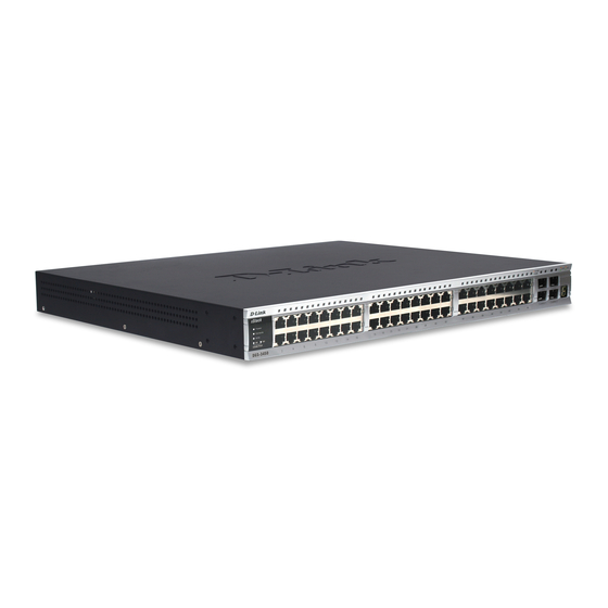
Stack ID number. A separate table below describes LED indicators in more detail. DGS-3426P also includes a Mode Select button for changing the mode Link/Act/State to PoE. DGS-3426 Figure 2- 1. Front Panel View of the DGS-3426 as shipped DGS-3426P Figure 2- 2. Front Panel View of the DGS-3426P as shipped DGS-3427 Figure 2- 3. -
Page 19: Led Indicators
The Switch supports LED indicators for Power, Console, RPS and Port LEDs including 10GE port LEDs for optional module inserts. Figure 2- 5. LED Indicators on DGS-3450 Figure 2- 6. LED Indicators on DGS-3427 Figure 2- 7. LED Indicators on DGS-3426 Figure 2- 8. LED Indicators on DGS-3426P... -
Page 20: Led Description
xStack DGS-3400 Series Layer 2 Gigabit Ethernet Managed Switch Description This LED will light green after powering the Switch on to indicate the ready state of the Power device. The indicator is dark when the Switch is no longer receiving power (i.e powered off). -
Page 21: Rear Panel Description
DGS-3400 Series Layer 2 Gigabit Ethernet Managed Switch Rear Panel Description DGS-3426 The rear panel of the DGS-3426 contains an AC power connector, a redundant power supply connector and two empty slots for optional module inserts. Figure 2- 9. Rear panel view of DGS-3426... -
Page 22: Side Panel Description
Switch for proper ventilation. Be reminded that without proper heat dissipation and air circulation, system components might overheat, which could lead to system failure and severely damage components. Figure 2- 13. Side Panels (DGS-3450) Figure 2- 14. Side Panels (DGS-3426 and DGS-3427) Figure 2- 15. Side Panels of the DGS-3426P... -
Page 23: Installation
7. One CD Kit for D-View 5.1 Standard version (for Europe only) 8. Registration card & China Warranty Card (for China only) If any item is missing or damaged, please contact your local D-Link Reseller for replacement. Installation Guidelines Please follow these guidelines for setting up the Switch: •... -
Page 24: Installing The Switch Without The Rack
xStack DGS-3400 Series Layer 2 Gigabit Ethernet Managed Switch Installing the Switch without the Rack First, attach the rubber feet included with the Switch if installing on a desktop or shelf. Attach these cushioning feet on the bottom at each corner of the device. Allow enough ventilation space between the Switch and any other objects in the vicinity. Figure 2- 16. -
Page 25: Mounting The Switch In A Standard 19" Rack
xStack DGS-3400 Series Layer 2 Gigabit Ethernet Managed Switch Mounting the Switch in a Standard 19" Rack Figure 2- 18. Installing Switch in a rack Power On 1. Plug one end of the AC power cord into the power connector of the Switch and the other end into the local power source outlet. -
Page 26: Installing The Sfp Ports
These SFP ports support full-duplex transmissions, have auto-negotiation and can be used with DEM-310GT (1000BASE-LX), DEM-311GT (1000BASE-SX), DEM-314GT (1000BASE-LH) and DEM-315GT (1000BASE-ZX) transceivers. See the figure below for installing the SFP ports in the Switch. Figure 2- 19. Inserting the fiber-optic transceivers into the DGS-3426... -
Page 27: The Optional Module
The Optional Module The rear panel of the DGS-3426, DGS-3426P, DGS-3427 and DGS-3450 include open slots that may be equipped with the DEM- 410X 1-port 10GE XFP stacking uplink module, or a DEM-410CX 1-port 10GBASE-CX4 stacking uplink module, both sold separately. -
Page 28: Installing The Module
xStack DGS-3400 Series Layer 2 Gigabit Ethernet Managed Switch Installing the Module Unplug the Switch before removing the faceplate covering the empty slot. To install the module, slide it in to the available slot at the rear of the Switch until it reaches the back, as shown in the following figure. Gently, but firmly push in on the module to secure it to the Switch. -
Page 29: External Redundant Power System
xStack DGS-3400 Series Layer 2 Gigabit Ethernet Managed Switch External Redundant Power System The Switch supports an external redundant power system. The diagrams below illustrate a proper RPS power connection to the Switch. Please consult the documentation for information on power cabling and connectors and setup procedure. Figure 2- 24. - Page 30 xStack DGS-3400 Series Layer 2 Gigabit Ethernet Managed Switch Alternate to the other Switches in the xStack DGS-3400 Switch Series, the DGS-3426P utilizes the DPS-600 as its External Redundant Power Supply. The DPS-600 is the ONLY RPS to be used with the DGS-3426P. NOTE: See the DPS-500 or DPS-600 documentation for more information.
-
Page 31: Connecting The Switch
xStack DGS-3400 Series Layer 2 Gigabit Ethernet Managed Switch Section 3 Connecting the Switch Switch to End Node Switch to Switch Connecting To Network Backbone or Server NOTE: All high-performance N-Way Ethernet ports can support both MDI-II and MDI-X connections. Switch to End Node End nodes include PCs outfitted with a 10, 100 or 1000 Mbps RJ-45 Ethernet Network Interface Card (NIC) and routers. -
Page 32: Connecting To Network Backbone Or Server
xStack DGS-3400 Series Layer 2 Gigabit Ethernet Managed Switch Connecting To Network Backbone or Server The combo SFP ports and the 1000BASE-T ports are ideal for uplinking to a network backbone, server or server farm. The copper ports operate at a speed of 1000, 100 or 10Mbps in full or half duplex mode. The fiber-optic ports can operate at 1000Mbps in full duplex mode only. -
Page 33: Introduction To Switch Management
xStack DGS-3400 Series Layer 2 Gigabit Ethernet Managed Switch Section 4 Introduction to Switch Management Management Options Connecting the Console Port (RS-232 DCE) First Time Connecting to the Switch Password Protection SNMP Settings IP Address Assignment Connecting Devices to the Switch Management Options This system may be managed out-of-band through the console port on the front panel or in-band using Telnet. -
Page 34: Connecting The Console Port (Rs-232 Dce)
xStack DGS-3400 Series Layer 2 Gigabit Ethernet Managed Switch Connecting the Console Port (RS-232 DCE) The Switch provides an RS-232 serial port that enables a connection to a computer or terminal for monitoring and configuring the Switch. This port is a female DB-9 connector, implemented as a data terminal equipment (DTE) connection. To use the console port, the following equipment is needed: •... -
Page 35: Managing The Switch For The First Time
Switch to refresh the console screen. Press Enter in both the Username and Password fields. Then access will be given to enter commands after the command prompt DGS-3426:4#, DGS-3426P:4#, DGS-3427:4# or DGS-3450:4# as shown below: DGS-3427 Gigabit Ethernet Switch Command Line Interface Firmware: Build 2.35-B09... -
Page 36: Password Protection
Press Enter in both the Username and Password fields. Then access will be given to enter commands after the command prompt DGS-3426:4#, DGS-3426P:4#, DGS-3427:4# or DGS-3450:4# as shown below: There is no initial username or password. Leave the Username and Password fields blank. -
Page 37: Snmp Settings
xStack DGS-3400 Series Layer 2 Gigabit Ethernet Managed Switch SNMP Settings Simple Network Management Protocol (SNMP) is an OSI Layer 7 (Application Layer) designed specifically for managing and monitoring network devices. SNMP enables network management stations to read and modify the settings of gateways, routers, switches and other network devices. -
Page 38: Ip Address Assignment
xStack DGS-3400 Series Layer 2 Gigabit Ethernet Managed Switch IP Address Assignment An IP Address must be assigned to each switch, which is used for communication with an SNMP network manager or other TCP/IP application (for example BOOTP, TFTP). The Switch's default IP address is 10.90.90.90. The user may change the default Switch IP address to meet the specification of your networking address scheme. - Page 39 xStack DGS-3400 Series Layer 2 Gigabit Ethernet Managed Switch DGS -3426:4#config ipif System ipaddress 10.73.21.35/255.0.0.0 Comand: config ipif System ipaddress 10.73.21.35/8 Success. DGS -3426:4# Figure 4- 5. Assigning the Switch an IP Address In the above example, the Switch was assigned an IP address of 10.53.13.26 with a subnet mask of 255.0.0.0. The system message Success indicates that the command was executed successfully.
-
Page 40: Web-Based Switch Configuration
xStack DGS-3400 Series Layer 2 Gigabit Ethernet Managed Switch Section 5 Web-based Switch Configuration Introduction Logging on to the Web Manager Web-Based User Interface Basic Setup Reboot Basic Switch Setup Network Management Switch Utilities Network Monitoring IGMP Snooping Status Introduction All software functions of the xStack DGS-3400 switch series can be managed, configured and monitored via the embedded web- based (HTML) interface. -
Page 41: Web-Based User Interface
xStack DGS-3400 Series Layer 2 Gigabit Ethernet Managed Switch Figure 5- 1. Enter Network Password window Leave both the User Name field and the Password field blank and click OK. This will open the Web-based user interface. The Switch management features available in the web-based manager are explained below. Web-based User Interface The user interface provides access to various Switch configuration and management screens, allows the user to view performance statistics, and permits graphical monitoring of the system status. -
Page 42: Web Pages
Area 1 Select the menu or window to display. Open folders and click the hyperlinked menu buttons and subfolders contained within them to display menus. Click the D-Link logo to go to the D-Link website. Area 2 Presents a graphical near real-time image of the front panel of the Switch. This area displays the Switch's ports and expansion modules, showing port activity, duplex mode, or flow control, depending on the specified mode. - Page 43 xStack DGS-3400 Series Layer 2 Gigabit Ethernet Managed Switch L2 Features – Contains the following menu pages and sub-directories: VLAN, Trunking, IGMP Snooping, MLD Snooping, Loopback Detection Global Settings, Spanning Tree and Forwarding & Filtering. QoS – Contains the following menu pages and sub-directories: Bandwidth Control, QoS Scheduling Mechanism, QoS Output Scheduling, 802.1p Default Priority and 802.1p User Priority.
-
Page 44: Configuring The Switch
xStack DGS-3400 Series Layer 2 Gigabit Ethernet Managed Switch Section 6 Configuring the Switch DGS-3400 Web Management Tool IP Address Interface Settings Stacking Port Configuration User Accounts Port Mirroring System Log System Severity Settings SNTP Settings MAC Notification Settings TFTP Services Multiple Image Services Ping Test Safeguard Engine... -
Page 45: Device Information
Some Functions are hyper-linked for easy access from the Device Information window. Many miscellaneous functions are enabled and disabled in the Device Information menu. NOTE: DGS-3426/DGS- 3427/DGS-3450/DGS-3426P will display the serial number in the Device Information window for Firmware 2.35.B09. - Page 46 xStack DGS-3400 Series Layer 2 Gigabit Ethernet Managed Switch default setting is 300 seconds. IGMP Snooping To enable system-wide IGMP Snooping capability, select Enabled. IGMP snooping is Disabled by default. Enabling IGMP snooping allows the user to specify use of a multicast router only (see below).
-
Page 47: Ipv6
xStack DGS-3400 Series Layer 2 Gigabit Ethernet Managed Switch IPv6 The xStack DGS-3400 has the capability to support the following: • IPv6 unicast, multicast and anycast addresses • Allow for IPv6 packet forwarding • IPv6 fragmentation and re-assembly • Processing of IPv6 packet and extension headers •... -
Page 48: Packet Format
xStack DGS-3400 Series Layer 2 Gigabit Ethernet Managed Switch Packet Format As in IPv4, the IPv6 packet consists of the packet header and the payload, but the difference occurs in the packet header which has been amended and improved for better packet flow and processing. The following will outline and detail the IPv6 enhancements and parts of the IPv6 packet, with special attention to the packet header. -
Page 49: Extension Headers
xStack DGS-3400 Series Layer 2 Gigabit Ethernet Managed Switch Extension Headers Extension headers are used to identify optional parameters regarding IPv6 packets such as routing, fragmentation of packets or authentication parameters. The types of extension headers supported are Hop-by-Hop, Routing, Fragment, Destination Options, Authentication and Encapsulating Security Payload. -
Page 50: Types
xStack DGS-3400 Series Layer 2 Gigabit Ethernet Managed Switch looks long and cumbersome, there are some compression rules that will shorten the format of the IPv6 address to make it more compatible to the user. One such compression rule that is used is to remove leading zeros from any 16-bit hexadecimal value. This is only for zeros that begin the value, not for zeros within the value or ones that are ending the value. -
Page 51: Icmpv6
xStack DGS-3400 Series Layer 2 Gigabit Ethernet Managed Switch ICMPv6 Network professionals are already very familiar with ICMP for IPv4, which is an essential tool in the IPv4 network, relaying messages about network problems and the general condition of the network. ICMPv6 is the successor to the IPv4 version and performs many of the same basic functions as its precursor, yet is not compatible with ICMPv4. -
Page 52: Duplicate Address Detection (Dad)
xStack DGS-3400 Series Layer 2 Gigabit Ethernet Managed Switch Duplicate Address Detection (DAD) DAD messages are used to specify that there is more than one node on a local link possessing the same IP address. IPv6 addresses are only leased for a defined period of time. When that time expires, the address will become invalid and another address must be addressed to the node. -
Page 53: Ip Address
xStack DGS-3400 Series Layer 2 Gigabit Ethernet Managed Switch IP Address The IP Address may initially be set using the console interface prior to connecting to it through the Ethernet. If the Switch IP address has not yet been changed, read the introduction of the xStack DGS-3400 Series CLI Manual or return to Section 4 of this manual for more information. -
Page 54: Setting The Switch's Ip Address Using The Console Interface
xStack DGS-3400 Series Layer 2 Gigabit Ethernet Managed Switch The following fields can be set or modified: Parameter Description BOOTP The Switch will send out a BOOTP broadcast request when it is powered up. The BOOTP protocol allows IP addresses, network masks, and default gateways to be assigned by a central BOOTP server. -
Page 55: Interface Settings
xStack DGS-3400 Series Layer 2 Gigabit Ethernet Managed Switch Interface Settings The IP Address may initially be set using the console interface prior to connecting to it through the Ethernet. If the Switch IP address has not yet been changed, read the introduction of the xStack DGS-3400 Series CLI Manual or return to Section 4 of this manual for more information. -
Page 56: Ipv6 Interface Settings
xStack DGS-3400 Series Layer 2 Gigabit Ethernet Managed Switch Enter a name for the new interface to be added in the Interface Name field (if editing an IP interface, the Interface Name will already be in the top field as seen in the window above). Enter the interface’s IP address and subnet mask in the corresponding fields. - Page 57 xStack DGS-3400 Series Layer 2 Gigabit Ethernet Managed Switch To change the settings for a configured Interface, click the corresponding Modify button, which will display the following window for the user to configure. Figure 6- 8. IPv6 Interface Settings – Edit The following fields may be viewed or modified.
- Page 58 xStack DGS-3400 Series Layer 2 Gigabit Ethernet Managed Switch and 255 with a default value of 64. IPv6 Address Use this field to set a Global Unicast Address for the Switch. This address will be used to access the network outside of the local link. NS Retransmit Time Use this field to set the interval, in seconds that this Switch will produce Neighbor Solicitation packets to be sent out over the local network.
- Page 59 xStack DGS-3400 Series Layer 2 Gigabit Ethernet Managed Switch RA Max Router Used to set the maximum interval time between the dispatch of router advertisements by AdvInterval this interface over the link-local network. This entry must be no less than 4 seconds (4000 milliseconds) and no more than 1800 seconds.
-
Page 60: Stacking
xStack DGS-3400 Series Layer 2 Gigabit Ethernet Managed Switch Stacking From firmware release v2.00 of this Switch, the xStack DGS-3400 series now supports switch stacking, where a set of twelve switches can be combined to be managed by one IP address through Telnet, the GUI interface (web), the console port or through SNMP. -
Page 61: Stack Switch Swapping
xStack DGS-3400 Series Layer 2 Gigabit Ethernet Managed Switch Backup Master – The Backup Master is the backup to the Primary Master, and will take over the functions of the Primary Master if the Primary Master fails or is removed from the Stack. It also monitors the status of neighboring switches in the stack, will perform commands assigned to it by the Primary Master and will monitor the running status of the Primary Master. -
Page 62: Stacking Mode Settings
xStack DGS-3400 Series Layer 2 Gigabit Ethernet Managed Switch NOTE: If there is a Box ID conflict when the stack is in the discovery phase, the device will enter a special standalone topology mode. Users can only get device information, configure Box IDs, save and reboot. -
Page 63: Port Configuration
xStack DGS-3400 Series Layer 2 Gigabit Ethernet Managed Switch Port Configuration Click Administration > Port Configuration > Port Configuration to display the following window: To configure switch ports: 1. Choose the port or sequential range of ports using the From…To… port pull-down menus. -
Page 64: Port Error Disabled
xStack DGS-3400 Series Layer 2 Gigabit Ethernet Managed Switch Flow Control Displays the flow control scheme used for the various port configurations. Ports configured for full-duplex use 802.3x flow control, half-duplex ports use backpressure flow control, and Auto ports use an automatic selection of the two. The default is Disabled. Learning Enable or disable MAC address learning for the selected ports. -
Page 65: Port Description
xStack DGS-3400 Series Layer 2 Gigabit Ethernet Managed Switch Port Description The Switch supports a port description feature where the user may name various ports on the Switch. To assign names to various ports, click Administration > Port Configuration > Port Description to view the following window: First use the Unit pull-down menu to choose the switch in the stack to be configured, and then the From and To... - Page 66 xStack DGS-3400 Series Layer 2 Gigabit Ethernet Managed Switch Figure 6- 16. Cable Diagnostics window...
-
Page 67: User Accounts
xStack DGS-3400 Series Layer 2 Gigabit Ethernet Managed Switch User Accounts Use the User Account Management window to control user privileges. To view existing User Accounts, click Administration > User Accounts, this will open the User Account Management window, as shown below. Figure 6- 17. -
Page 68: Port Mirroring
xStack DGS-3400 Series Layer 2 Gigabit Ethernet Managed Switch Port Mirroring The Switch allows you to copy frames transmitted and received on a port and redirect the copies to another port. You can attach a monitoring device to the mirrored port, such as a sniffer or an RMON probe, to view details about the packets passing through the first port. -
Page 69: Mirroing Within The Switch Stack
xStack DGS-3400 Series Layer 2 Gigabit Ethernet Managed Switch Mirroing within the Switch Stack Users may configure mirroring between switches in the switch stack but certain conditions and restrictions apply. 1. When mirroing is configured in the stack, the primary master and the backup master will save and synchronize these mirroring configurations in their respecitve databases. -
Page 70: System Log
xStack DGS-3400 Series Layer 2 Gigabit Ethernet Managed Switch System Log The Switch can send Syslog messages to up to four designated servers using the System Log Server. In the Administration folder, click System Log Settings > System Log Host, to view the window shown below. Figure 6- 21. -
Page 71: System Log Save Mode Settings
xStack DGS-3400 Series Layer 2 Gigabit Ethernet Managed Switch Configure the parameters listed below: Parameter Description Syslog server settings index (1-4). Index Server IP The IPv4 address of the Syslog server. Severity This drop-down menu allows you to select the level of messages that will be sent. The options are Warning, Informational, and All. - Page 72 xStack DGS-3400 Series Layer 2 Gigabit Ethernet Managed Switch Time Interval – Users who choose this method can configure a time interval by which the switch will save the log files, in the box adjacent to this configuration field. The user may set a time between 1 and 65535 minutes. The default setting is one minute. On Demand –...
-
Page 73: System Severity Settings
xStack DGS-3400 Series Layer 2 Gigabit Ethernet Managed Switch System Severity Settings The Switch can be configured to allow alerts be logged or sent as a trap to an SNMP agent or both. The level at which the alert triggers either a log entry or a trap message can be set as well. Use the System Severity Settings menu to set the criteria for alerts. The current settings are displayed below the System Severity Table. -
Page 74: Sntp Settings
xStack DGS-3400 Series Layer 2 Gigabit Ethernet Managed Switch SNTP Settings Time Settings To configure the time settings for the Switch, click Administration > SNTP Settings > Time Settings, the following window will be displayed. Figure 6- 26. Current Time: Status window The following parameters can be set or are displayed: Parameter Description... -
Page 75: Time Zone And Dst
xStack DGS-3400 Series Layer 2 Gigabit Ethernet Managed Switch Time in HH MM SS Enter the current time in hours, minutes, and seconds. Click Apply to implement your changes. Time Zone and DST The following are windows used to configure time zones and Daylight Savings time settings for SNTP. - Page 76 xStack DGS-3400 Series Layer 2 Gigabit Ethernet Managed Switch To: Day Enter the day of the monthDST will end on, each year. To: Time in HH:MM Enter the time of day that DST will end on, each year. Click Apply to implement changes made to the Time Zone and DST window.
-
Page 77: Mac Notification Settings
xStack DGS-3400 Series Layer 2 Gigabit Ethernet Managed Switch MAC Notification Settings MAC Notification is used to monitor MAC addresses learned and entered into the forwarding database. To globally set MAC notification on the Switch, open the following window by clicking Administration >... -
Page 78: Tftp Services
xStack DGS-3400 Series Layer 2 Gigabit Ethernet Managed Switch TFTP Services Trivial File Transfer Protocol (TFTP) services allow the Switch's firmware to be upgraded by transferring a new firmware file from a TFTP server to the Switch. A configuration file can also be downloaded into the Switch from a TFTP server. Switch configuration settings can be saved and a history and attack log can be uploaded from the Switch to the TFTP server. - Page 79 xStack DGS-3400 Series Layer 2 Gigabit Ethernet Managed Switch Server IPv6 Address Enter the IPv6 address of the server from which to download firmware. The Interface field is used for addresses on the link-local network. It is recommended that the user enter the specific interface for a link-local IPv6 address.
-
Page 80: Multiple Image Services
xStack DGS-3400 Series Layer 2 Gigabit Ethernet Managed Switch Multiple Image Services The Multiple Image Services folder allows users of the Switch to configure and view information regarding firmware located on the Switch. The Switch allows two firmware images to be stored in its memory and either can be configured to be the boot up firmware for the Switch. -
Page 81: Config Firmware Image
xStack DGS-3400 Series Layer 2 Gigabit Ethernet Managed Switch Config Firmware Image The following window is used to configure firmware set in the Switch. The Switch allows two firmware images to be stored in its memory and either can be configured to be the boot up firmware for the Switch. The user may select a boot up firmware image for the Switch in the switch stack by using the Image pull-down window to select it, change the Action to Boot and click Apply. -
Page 82: Ping Test
xStack DGS-3400 Series Layer 2 Gigabit Ethernet Managed Switch Ping Test Ping is a small program that sends ICMP Echo packets to the IP address you specify. The destination node then responds to or "echoes" the packets sent from the Switch. This is very useful to verify connectivity between the Switch and other nodes on the network. -
Page 83: Ipv6 Ping Test
xStack DGS-3400 Series Layer 2 Gigabit Ethernet Managed Switch IPv6 Ping Test The following window is used to Ping an IPv6 address. To locate this window, open the Administration > Ping Test > IPv6 Ping Test. Figure 6- 33. IPv6 Ping Test window This window allows the following parameters to be configured to ping an IPv6 address. -
Page 84: Safeguard Engine
xStack DGS-3400 Series Layer 2 Gigabit Ethernet Managed Switch Safeguard Engine Periodically, malicious hosts on the network will attack the Switch by utilizing packet flooding (ARP Storm) or other methods. These attacks may increase the switch load beyond its capability. To alleviate this problem, the Safeguard Engine function was added to the Switch’s software. -
Page 85: Safeguard Engine Settings
xStack DGS-3400 Series Layer 2 Gigabit Ethernet Managed Switch Safeguard Engine Settings To enable Safeguard Engine or configure advanced Safeguard Engine settings for the Switch, click Administration > Safeguard Engine > Safeguard Engine Settings, which will open the following window. Figure 6- 35. -
Page 86: Static Arp Settings
xStack DGS-3400 Series Layer 2 Gigabit Ethernet Managed Switch Static ARP Settings The Address Resolution Protocol (ARP) is a TCP/IP protocol that converts IP addresses into physical addresses. This table allows network managers to view, define, modify and delete ARP information for specific devices. Static entries can be defined in the ARP Table. -
Page 87: Ipv6 Neighbor
xStack DGS-3400 Series Layer 2 Gigabit Ethernet Managed Switch IPv6 Neighbor IPv6 neighbors are devices on the link-local network that have been detected as being IPv6 devices. These devices can forward packets and keep track of the reachability of routers, as well as if changes occur within link-layer addresses of nodes on the network or if identical unicast addresses are present on the local link. - Page 88 xStack DGS-3400 Series Layer 2 Gigabit Ethernet Managed Switch Figure 6- 41. IPv6 Neighbor Settings – Add window The following fields can be set or viewed: Parameter Description Interface Name Enter the name of the Interface associated with this entry, if any. The Interface field is used for addresses on the link-local network.
-
Page 89: Routing Table
xStack DGS-3400 Series Layer 2 Gigabit Ethernet Managed Switch Routing Table The Switch supports only static routing for IPv4 and IPv6 formatted addressing. Users can create up to 128 static route entries for IPv4 and IPv6 combined. Manually configured static routes can route IP packets, and the local route also can route IP packets. For each device that is a part of the DGS-3400 network, users may only configure one IP address as a static route. -
Page 90: Ipv6 Static/Default Route Settings
xStack DGS-3400 Series Layer 2 Gigabit Ethernet Managed Switch Figure 6- 43. Static/Default Route Settings – Add window The following fields can be set: Parameter Description IP Address Allows the entry of an IP address that will be a static entry into the Switch’s Routing Table. Subnet Mask Allows the entry of a subnet mask corresponding to the IP address above. - Page 91 xStack DGS-3400 Series Layer 2 Gigabit Ethernet Managed Switch Delete Click the button to delete this entry from the list. To enter an IPv6 Interface into the IPv6 Static Route list, click the Add button, revealing the following window to configure. Figure 6- 45.
-
Page 92: Dhcp/Bootp Relay
xStack DGS-3400 Series Layer 2 Gigabit Ethernet Managed Switch DHCP/BOOTP Relay The relay hops count limit allows the maximum number of hops (routers) that the DHCP/BOOTP messages can be relayed through to be set. If a packet’s hop count is more than the hop count limit, the packet is dropped. The range is between 1 and 16 hops, with a default value of 4. - Page 93 xStack DGS-3400 Series Layer 2 Gigabit Ethernet Managed Switch switch port that connects to the DHCP client that sent the DHCP request. Disabled- If the field is toggled to Disabled the relay agent will not insert and remove DHCP relay information (option 82 field) in messages between DHCP servers and clients, and the check and policy settings will have no effect.
-
Page 94: The Implementation Of Dhcp Information Option 82
xStack DGS-3400 Series Layer 2 Gigabit Ethernet Managed Switch The Implementation of DHCP Information Option 82 The config dhcp_relay option_82 command configures the DHCP relay agent information option 82 setting of the switch. The formats for the circuit ID sub-option and the remote ID sub-option are as follows: NOTE: For the circuit ID sub-option of a standalone switch, the module field is always zero. -
Page 95: Dhcp/Bootp Relay Interface Settings
xStack DGS-3400 Series Layer 2 Gigabit Ethernet Managed Switch DHCP/BOOTP Relay Interface Settings The DHCP/ BOOTP Relay Interface Settings allow the user to set up a server, by IP address, for relaying DHCP/ BOOTP information. The user may enter a previously configured IP interface on the Switch that will indicate which interface is able to support the dhcp relay function. -
Page 96: Dhcp Auto Configuration Settings
xStack DGS-3400 Series Layer 2 Gigabit Ethernet Managed Switch DHCP Auto Configuration Settings This window is used to enable the DHCP Autoconfiguration feature on the Switch. When enabled, the Switch is instructed to receive a configuration file from a TFTP server, which will set the Switch to become a DHCP client automatically on boot up. To employ this method, the DHCP server must be set up to deliver the TFTP server IP address and configuration file name information in the DHCP reply packet. -
Page 97: Snmp Manager
xStack DGS-3400 Series Layer 2 Gigabit Ethernet Managed Switch SNMP Manager Simple Network Management Protocol (SNMP) is an OSI Layer 7 (Application Layer) designed specifically for managing and monitoring network devices. SNMP enables network management stations to read and modify the settings of gateways, routers, switches, and other network devices. -
Page 98: Snmp Trap Settings
xStack DGS-3400 Series Layer 2 Gigabit Ethernet Managed Switch SNMP Trap Settings The following window is used to enable and disable trap settings for the SNMP function on the Switch. To view this window for configuration, click Administration > SNMP Manager > SNMP Trap Settings: Figure 6- 50. - Page 99 xStack DGS-3400 Series Layer 2 Gigabit Ethernet Managed Switch SNMP Version V1 - Indicates that SNMP version 1 is in use. V2 - Indicates that SNMP version 2 is in use. V3 - Indicates that SNMP version 3 is in use. None - Indicates that no authentication protocol is in use.
-
Page 100: Snmp View Table
xStack DGS-3400 Series Layer 2 Gigabit Ethernet Managed Switch SNMP View Table The SNMP View Table is used to assign views to community strings that define which MIB objects can be accessed by a remote SNMP manager. To view the SNMP View Table window, click, Administration > SNMP Manager > SNMP View Table. Figure 6- 54. -
Page 101: Snmp Group Table
xStack DGS-3400 Series Layer 2 Gigabit Ethernet Managed Switch To implement your new settings, click Apply. To return to the SNMP View Table, click the Show All SNMP View Table Entries link. SNMP Group Table An SNMP Group created with this table maps SNMP users (identified in the SNMP User Table) to the views created in the previous menu. - Page 102 xStack DGS-3400 Series Layer 2 Gigabit Ethernet Managed Switch Figure 6- 58. SNMP Group Table Configuration window The following parameters can set: Parameter Description Group Name Type an alphanumeric string of up to 32 characters. This is used to identify the new SNMP group of SNMP users.
-
Page 103: Snmp Community Table
xStack DGS-3400 Series Layer 2 Gigabit Ethernet Managed Switch SNMP Community Table Use this table to create an SNMP community string to define the relationship between the SNMP manager and an agent. The community string acts like a password to permit access to the agent on the Switch. One or more of the following characteristics can be associated with the community string: An Access List of IP addresses of SNMP managers that are permitted to use the community string to gain access to the Switch's SNMP agent. -
Page 104: Snmp Host Table
xStack DGS-3400 Series Layer 2 Gigabit Ethernet Managed Switch SNMP Host Table Use the SNMP Host Table window to set up SNMP trap recipients. To delete an existing SNMP Host Table entry, click the corresponding under the Delete heading. To display the current settings for an existing SNMP Group Table entry, click the blue link for the entry under the Host IP Address heading. -
Page 105: Snmp Engine Id
xStack DGS-3400 Series Layer 2 Gigabit Ethernet Managed Switch Figure 6- 62. SNMP IPv6 Host Table Configuration window The following parameters can set: Parameter Description Host IPv6 Address Type the IPv6 address of the remote management station that will serve as the SNMP host for the Switch. -
Page 106: Ip-Mac-Port Binding
xStack DGS-3400 Series Layer 2 Gigabit Ethernet Managed Switch IP-MAC-Port Binding The IP network layer uses a four-byte address. The Ethernet link layer uses a six-byte MAC address. Binding these two address types together allows the transmission of data between the layers. The primary purpose of IP-MAC binding is to restrict the access to a switch to a number of authorized users. - Page 107 xStack DGS-3400 Series Layer 2 Gigabit Ethernet Managed Switch Figure 6- 66. Access Rule Tables for IP-MAC Binding rule Figure 6- 67. Access Rule Display windows for IP MAC Binding NOTE: When configuring the ACL mode function of the IP-MAC binding function, please pay close attention to previously set ACL entries.
-
Page 108: Ip-Mac Binding Port
xStack DGS-3400 Series Layer 2 Gigabit Ethernet Managed Switch IP-MAC Binding Port This table is used to enable or disable IP-MAC binding on specific ports. Select a port or a range of ports with the From and To fields. Enable or disable the port with the State field. The user must also enable ports in this window to set the ACL Mode for IP-MAC Binding, as previously stated. -
Page 109: Ip-Mac Binding Table
xStack DGS-3400 Series Layer 2 Gigabit Ethernet Managed Switch IP-MAC Binding Table The window shown below can be used to create IP-MAC binding entries. Enter the IP and MAC addresses of the authorized users in the appropriate fields and click Add. To modify either the IP address or the MAC address of the binding entry, make the desired changes in the appropriate field and Click Modify. -
Page 110: Ip-Mac Binding Blocked
xStack DGS-3400 Series Layer 2 Gigabit Ethernet Managed Switch ARP – Choosing this selection will set a normal IP-MAC Binding entry for the IP address and MAC address entered. ACL – Choosing this entry will allow only packets from the source IP-MAC binding entry created here. -
Page 111: Poe Configuration
(Power Source over Ethernet) pinout Alternative A, whereby power is sent out over pins 1, 2, 3 and 6. The DGS-3426P works with all D-Link 802.3af capable devices. The Switch also works in PoE mode with all non-802.3af capable D-Link AP, IP Cam and IP phone equipment via DWL-P50. - Page 112 xStack DGS-3400 Series Layer 2 Gigabit Ethernet Managed Switch configured for the stack, whether or not the Switch is a PoE supported device. However, only PoE supported switches have the PoE capability in the switch stack. Power Limit Sets the limit of power to be used from the Switch’s power source to PoE ports. The user may configure a Power Limit between 37 and 370w.
-
Page 113: Poe Port Settings
xStack DGS-3400 Series Layer 2 Gigabit Ethernet Managed Switch PoE Port Settings The following window will allow the user to configure PoE settings for each port of the device. To open this window, click Administration > PoE > PoE Port Settings. Figure 6- 72. - Page 114 xStack DGS-3400 Series Layer 2 Gigabit Ethernet Managed Switch Priority option is chosen, and ports with a higher priority will take power precedence over low priority ports. Power Limit Sets the power limit per PoE port based on Class as described above. Once this threshold has been reached on the port, the PoE will go into the Power Disconnect Method, as described above.
-
Page 115: Single Ip Management (Sim) Overview
DGS-3400 Series Layer 2 Gigabit Ethernet Managed Switch Single IP Management (SIM) Overview Simply put, D-Link Single IP Management is a concept that will stack switches together over Ethernet instead of using stacking ports or modules. There are some advantages in implementing the "Single IP Management" feature: 1. -
Page 116: The Upgrade To V1.61
xStack DGS-3400 Series Layer 2 Gigabit Ethernet Managed Switch • A MS can become a CaS by: • Being configured as a CaS through the CS. • If report packets from the CS to the MS time out. • The user can manually configure a CaS to become a CS •... -
Page 117: Single Ip Vs. Switch Stacking
xStack DGS-3400 Series Layer 2 Gigabit Ethernet Managed Switch Single IP vs. Switch Stacking Single IP and Switch Stacking are two different entities and should not be equated by users. Within a switch stack, all functions are shared among switches in the stack and this switch stack is treated as one switch. Layer 2 and Layer 3 features, such as VLAN configurations and packet routing can be configured across switches in the stack. -
Page 118: Topology
xStack DGS-3400 Series Layer 2 Gigabit Ethernet Managed Switch Holdtime This parameter may be set for the time, in seconds; the Switch will hold information sent to it from other switches, utilizing the Discovery Interval. The user may set the hold time from 100 to 255 seconds. - Page 119 xStack DGS-3400 Series Layer 2 Gigabit Ethernet Managed Switch MAC Address Displays the MAC Address of the corresponding Switch. Model Name Displays the full Model Name of the corresponding Switch. To view the Topology Map, click the View menu in the toolbar and then Topology, which will produce the following screen. The Topology View will refresh itself periodically (20 seconds by default).
- Page 120 xStack DGS-3400 Series Layer 2 Gigabit Ethernet Managed Switch Layer 2 member switch. Layer 3 member switch Member switch of other group Layer 2 candidate switch Layer 3 candidate switch Unknown device Non-SIM devices...
-
Page 121: Tool Tips
xStack DGS-3400 Series Layer 2 Gigabit Ethernet Managed Switch Tool Tips In the Topology view window, the mouse plays an important role in configuration and in viewing device information. Setting the mouse cursor over a specific device in the topology window (tool tip) will display the same information about a specific device as the Tree view does. - Page 122 xStack DGS-3400 Series Layer 2 Gigabit Ethernet Managed Switch Figure 6- 78. Port Speed Utilizing the Tool Tip...
-
Page 123: Right Click
xStack DGS-3400 Series Layer 2 Gigabit Ethernet Managed Switch Right Click Right clicking on a device will allow the user to perform various functions, depending on the role of the Switch in the SIM group and the icon associated with it. Group Icon Figure 6- 79. -
Page 124: Commander Switch Icon
xStack DGS-3400 Series Layer 2 Gigabit Ethernet Managed Switch Port Speed Displays the connection speed between the CS and the MS or CaS Commander Switch Icon Figure 6- 81. Right Clicking a Commander Icon The following options may appear for the user to configure: •... -
Page 125: Menu Bar
xStack DGS-3400 Series Layer 2 Gigabit Ethernet Managed Switch Figure 6- 83. Right Clicking a Candidate icon The following options may appear for the user to configure: • Collapse - to collapse the group that will be represented by a single icon. •... -
Page 126: Firmware Upgrade
xStack DGS-3400 Series Layer 2 Gigabit Ethernet Managed Switch View • Refresh - update the views with the latest status. • Topology - display the Topology view. Help • About - Will display the SIM information, including the current SIM version. Figure 6- 87. -
Page 127: Upload Log
xStack DGS-3400 Series Layer 2 Gigabit Ethernet Managed Switch Figure 6- 89. Configuration File Backup/Restore window Upload Log The following window is used to upload log files from SIM member switches to a specified PC. To view this window, click Single IP Management >... -
Page 128: Layer 2 Features
xStack DGS-3400 Series Layer 2 Gigabit Ethernet Managed Switch Section 7 Layer 2 Features VLAN Trunking IGMP Snooping MLD Snooping Loopback Detection Global Settings Spanning Tree Forwarding and Filtering The following section will aid the user in configuring security functions for the Switch. The Switch includes various functions for VLAN, Trunking, IGMP Snooping, MLD Snooping, Loopback Dection Global Settings, Spanning Tree, and Forwarding &... -
Page 129: Notes About Vlans On The Dgs-3400 Series
xStack DGS-3400 Series Layer 2 Gigabit Ethernet Managed Switch equated to a broadcast domain, because broadcast packets are forwarded to only members of the VLAN on which the broadcast was initiated. Notes about VLANs on the DGS-3400 Series No matter what basis is used to uniquely identify end nodes and assign these nodes VLAN membership, packets cannot cross VLANs without a network device performing a routing function between the VLANs. -
Page 130: 802.1Q Vlan Tags
xStack DGS-3400 Series Layer 2 Gigabit Ethernet Managed Switch Figure 7- 1. IEEE 802.1Q Packet Forwarding 802.1Q VLAN Tags The figure below shows the 802.1Q VLAN tag. There are four additional octets inserted after the source MAC address. Their presence is indicated by a value of 0x8100 in the EtherType field. When a packet's EtherType field is equal to 0x8100, the packet carries the IEEE 802.1Q/802.1p tag. -
Page 131: Port Vlan Id
xStack DGS-3400 Series Layer 2 Gigabit Ethernet Managed Switch The EtherType and VLAN ID are inserted after the MAC source address, but before the original EtherType/Length or Logical Link Control. Because the packet is now a bit longer than it was originally, the Cyclic Redundancy Check (CRC) must be recalculated. -
Page 132: Ingress Filtering
xStack DGS-3400 Series Layer 2 Gigabit Ethernet Managed Switch will have no 802.1Q VLAN information. (Remember that the PVID is only used internally within the Switch). Untagging is used to send packets from an 802.1Q-compliant network device to a non-compliant network device. Ingress Filtering A port on a switch where packets are flowing into the Switch and VLAN decisions must be made is referred to as an ingress port. -
Page 133: Vlan Segmentation
xStack DGS-3400 Series Layer 2 Gigabit Ethernet Managed Switch VLAN Segmentation Take for example a packet that is transmitted by a machine on Port 1 that is a member of VLAN 2. If the destination lies on another port (found through a normal forwarding table lookup), the Switch then looks to see if the other port (Port 10) is a member of VLAN 2 (and can therefore receive VLAN 2 packets). - Page 134 xStack DGS-3400 Series Layer 2 Gigabit Ethernet Managed Switch Figure 7- 4. Current Static VLAN Entries window The Current Static VLAN Entries window lists all previously configured VLANs by VLAN ID and VLAN Name. To delete an existing 802.1Q VLAN, click the corresponding button under the Delete heading.
- Page 135 xStack DGS-3400 Series Layer 2 Gigabit Ethernet Managed Switch Figure 7- 6. Static VLAN window - Modify The following fields can then be set in either the Add or Modify 802.1Q Static VLANs windo Parameter Description Unit Select the switch in the switch stack for which to configure VLANs. VID (VLAN ID) Allows the entry of a VLAN ID in the Add window, or displays the VL AN ID of an existing VLAN in...
- Page 136 xStack DGS-3400 Series Layer 2 Gigabit Ethernet Managed Switch Novell NetWare 802.3 (IPX - Internet Packet Exchange). IPX 802.2 - Using this parameter will instruct the Switch to forward packets to this VLAN if the tag in the packet header is concurrent with this protocol. This packet header information is defined by Novell NetWare 802.2 (IPX - Internet Packet Exchange).
-
Page 137: Gvrp Settings
xStack DGS-3400 Series Layer 2 Gigabit Ethernet Managed Switch that will be transmitting traffic for the VLAN. These ports can be either tagged or untagged. Forbidden Select this to specify the port as not being a member of the VLAN and that the port is forbidd from becoming a member of the VLAN dynamically. -
Page 138: Double Vlans
xStack DGS-3400 Series Layer 2 Gigabit Ethernet Managed Switch PVID The read-only field in the 802.1Q Port Table shows the current PVID assignment for each port, which may be manually assigned to a VLAN when created in the 802.1Q Port Settings table. The Switch's default is to assign all ports to the default VLAN with a VID of 1.The PVID is used by the port to tag outgoing, untagged packets, and to make filtering decisions about incoming packets. -
Page 139: Regulations For Double Vlans
xStack DGS-3400 Series Layer 2 Gigabit Ethernet Managed Switch Figure 7- 8. Double VLAN Example In this example, the Service Provider Access Network switch (Provider edge switch) is the device creating and configuring Double VLANs. Both CEVLANs (Customer VLANs) 10 and 11, are tagged with the SPVID 100 on the Service Provider Access Network and therefore belong to one VLAN on the Service Provider’s network, thus being a member of two VLANs. -
Page 140: Double Vlan
xStack DGS-3400 Series Layer 2 Gigabit Ethernet Managed Switch Double VLAN To enable or disable the double VLAN State settings click, L2 Features > VLAN > Double VLAN Settings, which will display the following window. Figure 7- 9. Double VLAN State Settings Choose Enabled using the pull-down menu and click Apply. - Page 141 xStack DGS-3400 Series Layer 2 Gigabit Ethernet Managed Switch Figure 7- 11. Double VLAN Information window Parameters shown in the previous window are explained below: Parameter Description SPVID The VLAN ID number of this potential Service Provider VLAN. VLAN Name The name of the VLAN on the Switch.
-
Page 142: Pvid Auto Assign
xStack DGS-3400 Series Layer 2 Gigabit Ethernet Managed Switch Click Apply to implement changes made. To configure the parameters for a previously created Service Provider VLAN, click the button of the corresponding SPVID in the Double VLAN Table as shown in Figure 7-10. The following window will appear for the user to configure. Figure 7- 13. -
Page 143: Mac-Based Vlan Settings
xStack DGS-3400 Series Layer 2 Gigabit Ethernet Managed Switch Figure 7- 14. PVID Auto Assign Settings window When Enabled, PVID will be automatically assigned when adding a port to a VLAN as an untagged member port. MAC-based VLAN Settings This table is used to create new MAC Based VLAN entries and search, edit and delete existing entries. To view this window click L2 Features >... -
Page 144: Trunking
xStack DGS-3400 Series Layer 2 Gigabit Ethernet Managed Switch Trunking Understanding Port Trunk Groups Port trunk groups are used to combine a number of ports together to make a single high-bandwidth data pipeline. DGS-3400 Series supports up to 32 port trunk groups with 2 to 8 ports in each group. A potential bit rate of 8000 Mbps can be achieved. Figure 7- 16. -
Page 145: Link Aggregation
xStack DGS-3400 Series Layer 2 Gigabit Ethernet Managed Switch NOTE: If any ports within the trunk group become disconnected, packets intended for the disconnected port will be load shared among the other linked ports of the link aggregation group. NOTE: Trunking may be done across switches in the switch stack without any limitations. - Page 146 xStack DGS-3400 Series Layer 2 Gigabit Ethernet Managed Switch Figure 7- 18. Link Aggregation Settings – Add...
- Page 147 xStack DGS-3400 Series Layer 2 Gigabit Ethernet Managed Switch Figure 7- 19. Link Aggregation Settings window - Modify The user-changeable parameters are as follows: Parameter Description Group ID Select an ID number for the group, between 1 and 32. State Trunk groups can be toggled between Enabled and Disabled.
-
Page 148: Lacp Port Settings
xStack DGS-3400 Series Layer 2 Gigabit Ethernet Managed Switch After setting the previous parameters, click Apply to allow your changes to be implemented. Successfully created trunk groups will be show in the Current Link Aggregation Group Entries. NOTE: To configure the Algorithm for Link Aggregation, please refer back to the DGS- 3400 Web Management Tool and select the Link Aggregation Algorithm located on that web page. - Page 149 xStack DGS-3400 Series Layer 2 Gigabit Ethernet Managed Switch Figure 7- 20. LACP Port Settings window The user may set the following parameters: Parameter Description Unit Select the switch in the switch stack to be modified. From/To A consecutive group of ports may be configured starting with the selected port. Mode Active - Active LACP ports are capable of processing and sending LACP control frames.
- Page 150 xStack DGS-3400 Series Layer 2 Gigabit Ethernet Managed Switch is, to add or subtract ports from the group, at least one of the participating devices must designate LACP ports as active. Both devices must support LACP. Passive - LACP ports that are designated as passive cannot initially send LACP control frames. In order to allow the linked port group to negotiate adjustments and make changes dynamically, one end of the connection must have "active"...
-
Page 151: Igmp Snooping
xStack DGS-3400 Series Layer 2 Gigabit Ethernet Managed Switch IGMP Snooping Internet Group Management Protocol (IGMP) snooping allows the Switch to recognize IGMP queries and reports sent between network stations or devices and an IGMP host. When enabled for IGMP snooping, the Switch can open or close a port to a specific device based on IGMP messages passing through the Switch. -
Page 152: Router Port Settings
xStack DGS-3400 Series Layer 2 Gigabit Ethernet Managed Switch The following parameters may be viewed or modified: Parameter Description VLAN ID This is the VLAN ID that, along with the VLAN Name, identifies the VLAN the user wishes to modify the IGMP Snooping Settings for. VLAN Name This is the VLAN Name that, along with the VLAN ID, identifies the VLAN the user wishes to modify the IGMP Snooping Settings for. - Page 153 xStack DGS-3400 Series Layer 2 Gigabit Ethernet Managed Switch Figure 7- 23. Router Port Settings window The Router Ports Settings window displays all of the current entries to the Switch's static router port table. To modify an entry, click the Modify button. This will open the Router Port window, as shown below. Figure 7- 24.
-
Page 154: Ism Vlan
xStack DGS-3400 Series Layer 2 Gigabit Ethernet Managed Switch ports will not send out routing packets Click Apply to implement the new settings. ISM VLAN In a switching environment, multiple VLANs may exist. Every time a multicast query passes through the Switch, the switch must forward separate different copies of the data to each VLAN on the system, which, in turn, increases data traffic and may clog up the traffic path. - Page 155 xStack DGS-3400 Series Layer 2 Gigabit Ethernet Managed Switch Parameter Description VLAN Name This is the VLAN Name that, along with the VLAN ID, identifies the VLAN the user wishes to add. VID (2-4094) This is the VLAN ID that, along with the VLAN Name, identifies the VLAN the user wishes to add. To view the settings for all entries, click on the hyperlinked Show IGMP Snooping Multicast VLAN Entries, which will reveal the...
-
Page 156: Limited Multicast Address Range
xStack DGS-3400 Series Layer 2 Gigabit Ethernet Managed Switch Replace This parameter specifies the replacement for the source port of the ISM VLAN, which connects Source IP with the uplink server. To configure the IGMP Snooping Multicast VLAN Group List, click its corresponding button, which will produce the following window for the user to configure. - Page 157 xStack DGS-3400 Series Layer 2 Gigabit Ethernet Managed Switch Figure 7- 30. Limited Multicast Address Range Click Apply to implement the new settings on the Switch. Click Delete to remove the configured range from the settings. Click Delete All to delete all Limited IP Multicast settings. Parameter Description Unit...
-
Page 158: Mld Snooping
xStack DGS-3400 Series Layer 2 Gigabit Ethernet Managed Switch MLD Snooping Multicast Listener Discovery (MLD) Snooping is an IPv6 function used similarly to IGMP snooping in IPv4. It is used to discover ports on a VLAN that are requesting multicast data. Instead of flooding all ports on a selected VLAN with multicast traffic, MLD snooping will only forward multicast data to ports that wish to receive this data through the use of queries and reports produced by the requesting ports and the source of the multicast traffic. - Page 159 xStack DGS-3400 Series Layer 2 Gigabit Ethernet Managed Switch Figure 7- 32. MLD Snooping Settings - Edit window The following parameters may be viewed or modified: Parameter Description VLAN ID This is the VLAN ID that, along with the VLAN Name, identifies the VLAN for which to modify the MLD Snooping Settings.
-
Page 160: Mld Router Port Settings
xStack DGS-3400 Series Layer 2 Gigabit Ethernet Managed Switch Done Timer Specifies the maximum amount of time a router can remain in the Switch after receiving a done message from the group without receiving a node listener report. The user may specify a time between 1 and 16711450 with a default setting of 2 seconds. - Page 161 xStack DGS-3400 Series Layer 2 Gigabit Ethernet Managed Switch Figure 7- 34. Router Port- modify window The following parameters can be set: Parameter Description VID (VLAN ID) This is the VLAN ID that, along with the VLAN Name, identifies the VLAN where the MLD multicast router is attached.
-
Page 162: Loopback Detection Global Settings
xStack DGS-3400 Series Layer 2 Gigabit Ethernet Managed Switch Loopback Detection Global Settings The Loopback Detection function is used to identify loops occurring between the Switch and a device that is directly connected to it. This process is accomplished by the use of a Configuration Testing Protocol (CTP) packet that is generated by the switch. Users may set the dispatching time interval of the CTP packet and once a CTP packet has returned to the port from where it originated, the Loopback Detection function will disable this port until the anomaly has ceased, and the loopback occurrence will be noted in the Switch’s log. - Page 163 xStack DGS-3400 Series Layer 2 Gigabit Ethernet Managed Switch The following fields may be configured: Parameter Description Loopdetect Status Choose whether to globally enable or disable the Loopback Detection function by using this pull-down menu. Interval (1-32767) Enter a time interval, between 1 and 32767 seconds, that CTP packets will be dispatched from Loopback Detection enabled ports.
-
Page 164: Spanning Tree
STP will be familiar to most networking professionals. However, since 802.1w RSTP and 802.1s MSTP has been recently introduced to D-Link managed Ethernet switches, a brief introduction to the technology is provided below followed by a description of how to set up 802.1D STP, 802.1w RSTP and 802.1s MSTP. -
Page 165: Edge Port
xStack DGS-3400 Series Layer 2 Gigabit Ethernet Managed Switch All three protocols calculate a stable topology in the same way. Every segment will have a single path to the root bridge. All bridges listen for BPDU packets. However, BPDU packets are sent more frequently - with every Hello packet. BPDU packets are sent even if a BPDU packet was not received. -
Page 166: Stp Bridge Global Settings
xStack DGS-3400 Series Layer 2 Gigabit Ethernet Managed Switch STP Bridge Global Settings To open the following window, click Layer 2 Features > Spanning Tree > STP Bridge Global Settings link. Use the STP Status pull-down selector to enable or disable STP globally, and choose the STP method used with the STP Version menu. Figure 7- 36. - Page 167 xStack DGS-3400 Series Layer 2 Gigabit Ethernet Managed Switch Figure 7- 38. STP Bridge Global Settings – STP Compatible See the table below for descriptions of the STP versions and corresponding setting options. NOTE: The Hello Time cannot be longer than the Max. Age. Otherwise, a configuration error will occur.
- Page 168 xStack DGS-3400 Series Layer 2 Gigabit Ethernet Managed Switch Max Hops (1-20) Used to set the number of hops between devices in a spanning tree region before the BPDU (bridge protocol data unit) packet sent by the Switch will be discarded. Each switch on the hop count will reduce the hop count by one until the value reaches zero.
-
Page 169: Mst Configuration Identification
xStack DGS-3400 Series Layer 2 Gigabit Ethernet Managed Switch MST Configuration Identification The following screens in the MST Configuration Identification window allow the user to configure a MSTI instance on the Switch. These settings will uniquely identify a multiple spanning tree instance set on the Switch. The Switch initially possesses one CIST or Common Internal Spanning Tree of which the user may modify the parameters for but cannot change the MSTI ID for, and cannot be deleted. - Page 170 xStack DGS-3400 Series Layer 2 Gigabit Ethernet Managed Switch Parameter Description MSTI ID Enter a number between 1 and 15 to set a new MSTI on the Switch. Type Create is selected to create a new MSTI. No other choices are available for this field when creating a new MSTI.
-
Page 171: Mstp Port Information
xStack DGS-3400 Series Layer 2 Gigabit Ethernet Managed Switch The user may configure the following parameters for a MSTI on the Switch. Parameter Description MSTI ID Displays the MSTI ID previously set by the user. Type This field allows the user to choose a desired method for altering the MSTI settings. The user has four choices. - Page 172 xStack DGS-3400 Series Layer 2 Gigabit Ethernet Managed Switch The user may configure the following parameters: Parameter Description Instance ID Displays the MSTI ID of the instance being configured. An entry of 0 in this field denotes the CIST (default MSTI). Internal Cost This parameter is set to represent the relative cost of forwarding packets to specified ports (0=Auto)
-
Page 173: Stp Instance Settings
xStack DGS-3400 Series Layer 2 Gigabit Ethernet Managed Switch STP Instance Settings The following window displays MSTIs currently set on the Switch. To view the following table, click Layer 2 Features > Spanning Tree > STP Instance Settings: Figure 7- 45. STP Instance Table The following information is displayed: Parameter Description... -
Page 174: Stp Port Settings
xStack DGS-3400 Series Layer 2 Gigabit Ethernet Managed Switch STP Port Settings STP can be set up on a port per port basis. To view the STP Port Settings window click Layer 2 Features > Spanning Tree > STP Port Settings: In addition to setting Spanning Tree parameters for use on the switch level, the Switch allows... - Page 175 xStack DGS-3400 Series Layer 2 Gigabit Ethernet Managed Switch duplex. Like edge ports, P2P ports transition to a forwarding state rapidly thus benefiting from RSTP. A p2p value of False indicates that the port cannot have p2p status. Auto allows the port to have p2p status whenever possible and operate as if the p2p status were true.
-
Page 176: Forwarding & Filtering
xStack DGS-3400 Series Layer 2 Gigabit Ethernet Managed Switch Forwarding & Filtering Unicast Forwarding To view this window click, Layer 2 Features > Forwarding & Filtering > Unicast For- warding. Figure 7- 48. Setup Static Unicast Forwarding Table window To add or edit an entry, define the following parameters and then click Add/Modify: Parameter Description VLAN ID (VID) -
Page 177: Multicast Filtering Mode
xStack DGS-3400 Series Layer 2 Gigabit Ethernet Managed Switch Figure 7- 50. Setup Static Multicast Forwarding Table window The following parameters can be set: Parameter Description Unit Select the switch in the switch stack to be modified. The VLAN ID of the VLAN the corresponding MAC address belongs to. Multicast MAC The MAC address of the static source of multicast packets. - Page 178 xStack DGS-3400 Series Layer 2 Gigabit Ethernet Managed Switch Parameter Description VLAN Name The VLAN to which the specified filtering action applies. Select the All option to apply the action to all VLANs on the Switch. Filtering Mode This drop-down menu allows you to select the action the Switch will take when it receives a multicast packet that requires forwarding to a port in the specified VLAN.
-
Page 179: Qos
xStack DGS-3400 Series Layer 2 Gigabit Ethernet Managed Switch Section 8 Bandwidth Control QoS Scheduling Mechanism QoS Output Scheduling 802.1P Default Priority 802.1P User Priority The xStack DGS-3400 switch series supports 802.1p priority queuing Quality of Service. The following section discusses the implementation of QoS (Quality of Service) and benefits of using 802.1p priority queuing. -
Page 180: Understanding Qos
xStack DGS-3400 Series Layer 2 Gigabit Ethernet Managed Switch Figure 8- 1. An Example of the Default QoS Mapping on the Switch The picture above shows the default priority setting for the Switch. Class-6 has the highest priority of the seven priority classes of service on the Switch. - Page 181 xStack DGS-3400 Series Layer 2 Gigabit Ethernet Managed Switch • Priority 0 is assigned to the Switch’s Q2 queue. • Priority 1 is assigned to the Switch’s Q0 queue. • Priority 2 is assigned to the Switch’s Q1 queue. • Priority 3 is assigned to the Switch’s Q3 queue.
-
Page 182: Bandwidth Control
xStack DGS-3400 Series Layer 2 Gigabit Ethernet Managed Switch Bandwidth Control The bandwidth control settings are used to place a ceiling on the transmitting and receiving data rates for any selected port. To view this window click, QoS > Bandwidth Control. Figure 8- 2. -
Page 183: Qos Scheduling Mechanism
xStack DGS-3400 Series Layer 2 Gigabit Ethernet Managed Switch No Limit This drop-down menu allows the user to specify that the selected port will have no bandwidth limit. Enabled disables the limit. Rate This field allows the input of the data rate that will be the limit for the selected port. The user may choose a rate between 1 and 156249 units, where each unit is defined a 64Kbit/s. -
Page 184: Qos Output Scheduling
xStack DGS-3400 Series Layer 2 Gigabit Ethernet Managed Switch QoS Output Scheduling QoS can be customized by changing the output scheduling used for the hardware classes of service in the Switch. As with any changes to QoS implementation, careful consideration should be given to how network traffic in lower priority classes of service is affected. -
Page 185: Configuring The Combination Queue
xStack DGS-3400 Series Layer 2 Gigabit Ethernet Managed Switch Configuring the Combination Queue Utilizing the QoS Output Scheduling Configuration window shown above, the xStack DGS-3400 series can implement a combination queue for forwarding packets. This combination queue allows for a combination of strict and weight-fair (weighted round-robin “WRR”) scheduling for emptying given classes of service. -
Page 186: 802.1P Default Priority
xStack DGS-3400 Series Layer 2 Gigabit Ethernet Managed Switch 802.1P Default Priority The Switch allows the assignment of a default 802.1p priority to each port on the Switch. The priority tags are numbered from 0, the lowest priority, to 7, the highest priority. Click QoS > 802.1p Default Priority, to view the screen shown below. Figure 8- 6. -
Page 187: 802.1P User Priority
xStack DGS-3400 Series Layer 2 Gigabit Ethernet Managed Switch 802.1P User Priority The xStack DGS-3400 switch series allows the assignment of a class of service to each of the 802.1p priorities. Click, QoS > 802.1p User Priority, to view the screen shown below. Figure 8- 7. -
Page 188: Acl (Access Control List)
xStack DGS-3400 Series Layer 2 Gigabit Ethernet Managed Switch Section 9 ACL (Access Control List) Time Range Access Profile Table CPU Interface Filtering Time Range The Time Range window is used in conjunction with the Access Profile feature to determine a starting point and an ending point, based on days of the week, when an Access Profile configuration will be enabled on the Switch. - Page 189 xStack DGS-3400 Series Layer 2 Gigabit Ethernet Managed Switch Weekdays Use the check boxes to select the corresponding days of the week that this time range is to be enabled. Click the Select All Days check box to configure this time range for every day of the week.
-
Page 190: Access Profile Table
xStack DGS-3400 Series Layer 2 Gigabit Ethernet Managed Switch Access Profile Table Access profiles allow you to establish criteria to determine whether the Switch will forward packets based on the information contained in each packet's header. These criteria can be specified on a basis of VLAN, MAC address or IP address. Creating an access profile is divided into two basic parts. - Page 191 xStack DGS-3400 Series Layer 2 Gigabit Ethernet Managed Switch Select IPv6 to instruct the Switch to examine the IPv6 address in each frame's header. VLAN Selecting this option instructs the Switch to examine the VLAN identifier of each packet header and use this as the full or partial criterion for forwarding.
- Page 192 xStack DGS-3400 Series Layer 2 Gigabit Ethernet Managed Switch Figure 9- 5. Access Profile Configuration (IP) The following parameters can be set, for IP: Parameter Description Profile ID (1-6) Type in a unique identifier number for this profile set. This value can be set from 1 -6. Type Select profile based on Ethernet (MAC Address), IP or IPv6 address.
- Page 193 xStack DGS-3400 Series Layer 2 Gigabit Ethernet Managed Switch 0xffff), which you wish to filter. dst port mask - Specify a TCP port mask for the destination port in hex form (hex • 0x0-0xffff) which you wish to filter. flag bit - The user may also identify which flag bits to filter. Flag bits are parts of a •...
- Page 194 xStack DGS-3400 Series Layer 2 Gigabit Ethernet Managed Switch The following parameters can be set, for IP: Parameter Description Profile ID (1-6) Type in a unique identifier number for this profile set. This value can be set from 1 - 6. Type Select profile based on Ethernet (MAC Address), IP or IPv6 address.
- Page 195 xStack DGS-3400 Series Layer 2 Gigabit Ethernet Managed Switch To establish the rule for a previously created Access Profile: To configure the Access Rule for Ethernet, open the Access Profile Table and click Modify for an Ethernet entry. This will open the following screen: Figure 9- 9.
- Page 196 xStack DGS-3400 Series Layer 2 Gigabit Ethernet Managed Switch for the rule being created. Selected profile based on Ethernet (MAC Address), IP address or IPv6 address Type Ethernet instructs the Switch to examine the layer 2 part of each packet header. IP instructs the Switch to examine the IP address in each frame's header.
- Page 197 xStack DGS-3400 Series Layer 2 Gigabit Ethernet Managed Switch Figure 9- 11. Access Rule Display window (Ethernet) In the ACL folder, click the Access Profile Table link opening the Access Profile Table. Under the heading Access Rule, clicking Modify, will open the following window. Figure 9- 12.
- Page 198 xStack DGS-3400 Series Layer 2 Gigabit Ethernet Managed Switch Figure 9- 13. Access Rule Configuration window (IP) Configure the following Access Rule Configuration settings for IP: Parameter Description Profile ID This is the identifier number for this profile set. Mode Select Permit to specify that the packets that match the access profile are forwarded by the Switch, according to any additional rule added (see below).
- Page 199 xStack DGS-3400 Series Layer 2 Gigabit Ethernet Managed Switch Destination IP Destination IP Address- Enter an IP Address mask for the destination IP address. This field allows the user to enter a DSCP value in the space provided, which will instruct the DSCP (0-63) Switch to examine the DiffServ Code part of each packet header and use this as the, or part of the criterion for forwarding.
- Page 200 xStack DGS-3400 Series Layer 2 Gigabit Ethernet Managed Switch Figure 9- 15. Access Rule Table Click Add Rule to open the next screen to configure the IPv6 entry for an access rule. Figure 9- 16. Access Rule Configuration – IPv6 To set the Access Rule for the Packet Content Mask, adjust the following parameters and click Apply.
- Page 201 xStack DGS-3400 Series Layer 2 Gigabit Ethernet Managed Switch specified, packets accepted by the Switch that match this priority are forwarded to the CoS queue specified previously by the user. replace priority − Click the corresponding box to re-write the 802.1p default priority of a packet to the value entered in the Priority field, which meets the criteria specified previously in this command, before forwarding it on to the specified CoS queue.
- Page 202 xStack DGS-3400 Series Layer 2 Gigabit Ethernet Managed Switch Figure 9- 17. Access Rule Display (IPv6)
-
Page 203: Cpu Interface Filtering
xStack DGS-3400 Series Layer 2 Gigabit Ethernet Managed Switch CPU Interface Filtering Due to a chipset limitation and needed extra switch security, the xStack DGS-3400 Series switch incorporates CPU Interface filtering. This added feature increases the running security of the Switch by enabling the user to create a list of access rules for packets destined for the Switch’s CPU interface. - Page 204 xStack DGS-3400 Series Layer 2 Gigabit Ethernet Managed Switch Figure 9- 20. CPU Interface Filtering Configuration window – Ethernet Parameter Description Profile ID (1-5) Type in a unique identifier number for this profile set. This value can be set from 1 - 5. Type Select profile based on Ethernet (MAC Address), IP address or packet content mask.
- Page 205 xStack DGS-3400 Series Layer 2 Gigabit Ethernet Managed Switch Figure 9- 21. CPU Interface Filtering Entry Display for Ethernet The page shown below is the CPU Interface Filtering Profile Configuration for IP page. Figure 9- 22. CPU Interface Filtering Configuration window- IP The following parameters may be configured for the IP CPU filter.
- Page 206 xStack DGS-3400 Series Layer 2 Gigabit Ethernet Managed Switch Select Ethernet to instruct the Switch to examine the layer 2 part of each packet header. Select IP to instruct the Switch to examine the IP address in each frame's header. Select Packet Content Mask to specify a mask to hide the content of the packet header.
- Page 207 xStack DGS-3400 Series Layer 2 Gigabit Ethernet Managed Switch Figure 9- 23. CPU Interface Filtering Entry Display for IP The page shown below is the Packet Content Mask configuration window. Figure 9- 24. CPU Interface Filtering Configuration window- Packet Content...
- Page 208 xStack DGS-3400 Series Layer 2 Gigabit Ethernet Managed Switch This screen will aid the user in configuring the Switch to mask packet headers beginning with the offset value specified. The following fields are used to configure the Packet Content Mask: Parameter Description Profile ID (1-5)
- Page 209 xStack DGS-3400 Series Layer 2 Gigabit Ethernet Managed Switch Figure 9- 26. CPU Interface Filtering Table In this window, the user may add a rule to a previously created CPU access profile by clicking the corresponding Modify button of the entry to configure, Ethernet, IP or Packet Content. Each entry will open a new and unique window, as shown in the examples below.
- Page 210 xStack DGS-3400 Series Layer 2 Gigabit Ethernet Managed Switch To set the CPU Interface Filtering Rule for Ethernet, adjust the following parameters and click Apply. Parameter Description Profile ID This is the identifier number for this profile set. Mode Select Permit to specify that the packets that match the access profile are forwarded by the Switch, according to any additional rule added (see below).
- Page 211 xStack DGS-3400 Series Layer 2 Gigabit Ethernet Managed Switch To view the settings of a previously correctly configured rule, click in the Access Rule Table to view the following screen: Figure 9- 29. CPU Interface Filtering Rule Display – Ethernet The following window is the CPU Interface Filtering Rule Table for IP.
- Page 212 xStack DGS-3400 Series Layer 2 Gigabit Ethernet Managed Switch Figure 9- 31. CPU Interface Filtering Rule Configuration – IP Configure the following Access Rule Configuration settings for IP: Parameter Description Profile ID This is the identifier number for this profile set. Mode Select Permit to specify that the packets that match the access profile are forwarded by the Switch, according to any additional rule added (see below).
- Page 213 xStack DGS-3400 Series Layer 2 Gigabit Ethernet Managed Switch Figure 9- 32. CPU Interface Filtering Rule Display - IP The following window is the CPU Interface Filtering Rule Table for Packet Content. Figure 9- 33. CPU Interface Filtering Rule Table – Packet Content To remove a previously created rule, select it and click the button.
- Page 214 xStack DGS-3400 Series Layer 2 Gigabit Ethernet Managed Switch Figure 9- 34. CPU Interface Filtering Rule Configuration - Packet Content...
- Page 215 xStack DGS-3400 Series Layer 2 Gigabit Ethernet Managed Switch To set the Access Rule for Packet Content, adjust the following parameters and click Apply. Parameter Description This is the identifier number for this profile set. Profile ID Mode Select Permit to specify that the packets that match the access profile are forwarded by the Switch, according to any additional rule added (see below).
-
Page 216: Security
xStack DGS-3400 Series Layer 2 Gigabit Ethernet Managed Switch Section 10 Security Authorization Network State Settings Traffic Control Port Security 802.1X Trust Host Access Authentication Control MAC Based Access Control Traffic Segmentation JWAC Authorization Network State Settings This window is used to Enable or Disable the Authorization Network State Settings, to view this window click Security Management >... -
Page 217: Traffic Control
xStack DGS-3400 Series Layer 2 Gigabit Ethernet Managed Switch Traffic Control On a computer network, packets such as Multicast packets Broadcast packets continually flood the network as normal procedure. At times, this traffic may increase do to a malicious endstation on the network or a malfunctioning device, such as a faulty network card. - Page 218 xStack DGS-3400 Series Layer 2 Gigabit Ethernet Managed Switch Storm Cleared – Will send Storm Trap messages when a Traffic Storm has been cleared • by the Switch only. Both – Will send Storm Trap messages when a Traffic Storm has been both detected and •...
-
Page 219: Port Security
xStack DGS-3400 Series Layer 2 Gigabit Ethernet Managed Switch Port Security A given port’s (or a range of ports') dynamic MAC address learning can be locked such that the current source MAC addresses entered into the MAC address forwarding table can not be changed once the port lock is enabled. -
Page 220: Port Security Entries
xStack DGS-3400 Series Layer 2 Gigabit Ethernet Managed Switch Click Apply to implement changes made. Port Security Entries The Port Lock Entry Delete window is used to remove an entry from the port security entries learned by the Switch and entered into the forwarding database. -
Page 221: 207
xStack DGS-3400 Series Layer 2 Gigabit Ethernet Managed Switch 802.1X 802.1x Port-Based and MAC-Based Access Control The IEEE 802.1x standard is a security measure for authorizing and authenticating users to gain access to various wired or wireless devices on a specified Local Area Network by using a Client and Server based access control model. This is accomplished by using a RADIUS server to authenticate users trying to access a network by relaying Extensible Authentication Protocol over LAN (EAPOL) packets between the Client and the Server. - Page 222 xStack DGS-3400 Series Layer 2 Gigabit Ethernet Managed Switch Figure 10- 7. The Authentication Server Authenticator The Authenticator (the Switch) is an intermediary between the Authentication Server and the Client. The Authenticator serves two purposes when utilizing 802.1x. The first purpose is to request certification information from the Client through EAPOL packets, which is the only information allowed to pass through the Authenticator before access is granted to the Client.
-
Page 223: Authentication Process
Figure 10- 10. The 802.1X Authentication Process The D-Link implementation of 802.1x allows network administrators to choose between two types of Access Control used on the Switch, which are: 1. Port-Based Access Control – This method requires only one user to be authenticated per port by a remote RADIUS server to allow the remaining users on the same port access to the network. - Page 224 xStack DGS-3400 Series Layer 2 Gigabit Ethernet Managed Switch Port-Based Network Access Control RADIUS Server Ethernet Switch … 802.1X 802.1X 802.1X 802.1X 802.1X 802.1X 802.1X 802.1X 802.1X Client Client Client Client Client Client Client Client Client Network access controlled port Network access uncontrolled port Figure 10- 11.
- Page 225 xStack DGS-3400 Series Layer 2 Gigabit Ethernet Managed Switch MAC-Based Network Access Control RADIUS Server Ethernet Switch … 802.1X 802.1X 802.1X 802.1X 802.1X 802.1X 802.1X 802.1X 802.1X 802.1X 802.1X 802.1X Client Client Client Client Client Client Client Client Client Client Client Client Network access controlled port...
-
Page 226: Guest Vlans
xStack DGS-3400 Series Layer 2 Gigabit Ethernet Managed Switch Guest VLANs On 802.1X security enabled networks, there is a need for non 802.1X supported devices to gain limited access to the network, due to the lack of the proper 802.1X software or incompatible devices, such as computers running Windows 98 or lower operating systems, or the need for guests to gain access to the network without full authorization or local authentication on the... -
Page 227: Configure 802.1X Authenticator
xStack DGS-3400 Series Layer 2 Gigabit Ethernet Managed Switch Configure 802.1X Authenticator To configure the 802.1X authenticator settings, click Security > 802.1X > Configure 802.1X Authenticator Parameter. The user may toggle between switches in the switch stack by using the Unit pull-down menu. Figure 10- 14. - Page 228 xStack DGS-3400 Series Layer 2 Gigabit Ethernet Managed Switch Figure 10- 15. 802.1X Authenticator Settings of Unit 1 – Modify This screen allows setting of the following features: Parameter Description Choose the Switch ID number of the Switch in the switch stack to be modified. Unit From [ ] To [ ] Enter the port or ports to be set.
-
Page 229: Configure 802.1X Guest Vlan
xStack DGS-3400 Series Layer 2 Gigabit Ethernet Managed Switch QuietPeriod This allows the user to set the number of seconds that the Switch remains in the quiet state following a failed authentication exchange with the client. The default setting is 60 seconds. SuppTimeout This value determines timeout conditions in the exchanges between the Authenticator and the client. -
Page 230: Authentic Radius Server
xStack DGS-3400 Series Layer 2 Gigabit Ethernet Managed Switch Authentic RADIUS Server The RADIUS feature of the Switch allows the user to facilitate centralized user administration as well as providing protection against a sniffing, active hacker. The Web Manager offers three windows. Click Security >... -
Page 231: Trust Host
xStack DGS-3400 Series Layer 2 Gigabit Ethernet Managed Switch Trust Host Up to four trusted-host secure IP addresses may be configured and used for remote Switch management. It should be noted that if one or more trusted hosts are enabled, the Switch will immediately accept remote instructions from only the specified IP address or addresses. -
Page 232: Access Authentication Control
xStack DGS-3400 Series Layer 2 Gigabit Ethernet Managed Switch Access Authentication Control The TACACS / XTACACS / TACACS+ / RADIUS commands allow users to secure access to the Switch using the TACACS / XTACACS / TACACS+ / RADIUS protocols. When a user logs in to the Switch or tries to access the administrator level privilege, he or she is prompted for a password. -
Page 233: Authentication Policy & Parameters
xStack DGS-3400 Series Layer 2 Gigabit Ethernet Managed Switch Authentication Policy & Parameters This command will enable an administrator-defined authentication policy for users trying to access the Switch. When enabled, the device will check the Login Method List and choose a technique for user authentication upon login. To access the following window, click Security >... -
Page 234: Authentication Server Group
xStack DGS-3400 Series Layer 2 Gigabit Ethernet Managed Switch Interface) application, the Telnet application, SSH and the Web (HTTP) application. Login Method List Using the pull down menu, configure an application for normal login on the user level, utilizing a previously configured method list. The user may use the default Method List or other Method List configured by the user. -
Page 235: Authentication Server Host
xStack DGS-3400 Series Layer 2 Gigabit Ethernet Managed Switch To add an Authentication Server Host to the list, enter its IP address in the IP Address field, choose the protocol associated with the IP address of the Authentication Server Host and click Add to add this Authentication Server Host to the group. To add a server group other than the ones listed, click the add button, revealing the following window to configure. - Page 236 xStack DGS-3400 Series Layer 2 Gigabit Ethernet Managed Switch Figure 10- 25. Authentication Server Host Setting - Add window Configure the following parameters to add an Authentication Server Host: Parameter Description IP Address The IP address of the remote server host to add. Protocol The protocol used by the server host.
-
Page 237: Login Method Lists
xStack DGS-3400 Series Layer 2 Gigabit Ethernet Managed Switch Login Method Lists This command will configure a user-defined or default Login Method List of authentication techniques for users logging on to the Switch. The sequence of techniques implemented in this command will affect the authentication result. For example, if a user enters a sequence of techniques, for example TACACS - XTACACS- local, the Switch will send an authentication request to the first TACACS host in the server group. -
Page 238: Enable Method Lists
xStack DGS-3400 Series Layer 2 Gigabit Ethernet Managed Switch Figure 10- 28. Login Method List – Add window To define a Login Method List, set the following parameters and click Apply: Parameter Description Method List Name Enter a method list name defined by the user of up to 15 characters. Method 1, 2, 3, 4 The user may add one, or a combination of up to four (4) of the following authentication methods to this method list:... - Page 239 xStack DGS-3400 Series Layer 2 Gigabit Ethernet Managed Switch To view the following table, click Security > Access Authentication Control > Enable Method Lists: Figure 10- 29. Enable Method List Settings window To delete an Enable Method List defined by the user, click the under the Delete heading corresponding to the entry desired to be deleted.
- Page 240 xStack DGS-3400 Series Layer 2 Gigabit Ethernet Managed Switch in the next section entitled Local Enable Password. none - Adding this parameter will require no authentication to access the Switch. radius - Adding this parameter will require the user to be authenticated using the RADIUS protocol from a remote RADIUS server.
-
Page 241: Configure Local Enable Password
xStack DGS-3400 Series Layer 2 Gigabit Ethernet Managed Switch Configure Local Enable Password This window will configure the locally enabled password for the Enable Admin command. When a user chooses the "local_enable" method to promote user level privileges to administrator privileges, he or she will be prompted to enter the password configured here that is locally set on the Switch. -
Page 242: Mac Based Access Control
xStack DGS-3400 Series Layer 2 Gigabit Ethernet Managed Switch MAC Based Access Control MAC Based Access Control Global Settings The following window is used to set the parameters for the MAC-Based Access Control function on the Switch. Here the user can set the state, password, authentication method, aswell as create, config or delete Guest VLANs. -
Page 243: Mac Based Access Control Local Mac Settings
xStack DGS-3400 Series Layer 2 Gigabit Ethernet Managed Switch The following parameters may be viewed or set: Parameter Description Settings State Use the pull-down menu to globally enable or disable the MAC-Based Access Control function on the Switch. Method Use the pull-down menu to choose the type of authentication to be used when authentication MAC addresses on a given port. - Page 244 xStack DGS-3400 Series Layer 2 Gigabit Ethernet Managed Switch Figure 10- 35. MAC Based Access Control Local MAC Settings To add a MAC address to the local authentication list, enter the MAC address and the target VLAN name into their appropriate fields and click Apply.
-
Page 245: Traffic Segmentation
xStack DGS-3400 Series Layer 2 Gigabit Ethernet Managed Switch Traffic Segmentation Traffic segmentation is used to limit traffic flow from a single port to a group of ports. This method of segmenting the flow of traffic is similar to using VLANs to limit traffic, but is more restrictive. It provides a method of directing traffic that does not increase the overhead of the Master switch CPU. -
Page 246: Secure Socket Layer (Ssl)
xStack DGS-3400 Series Layer 2 Gigabit Ethernet Managed Switch Secure Socket Layer (SSL) Secure Sockets Layer or SSL is a security feature that will provide a secure communication path between a host and client through the use of authentication, digital signatures and encryption. These security functions are implemented through the use of a ciphersuite, which is a security string that determines the exact cryptographic parameters, specific encryption algorithms and key sizes to be used for an authentication session and consists of three levels: 1. -
Page 247: Ssl Configuration
xStack DGS-3400 Series Layer 2 Gigabit Ethernet Managed Switch Parameter Description Certificate Type Select Local to specify certificate type. Server IP Enter the IPv4 address of the TFTP server where the certificate files are located. Certificate File Name Enter the path and the filename of the certificate file to download. This file must have a .der extension. - Page 248 xStack DGS-3400 Series Layer 2 Gigabit Ethernet Managed Switch RSA with 3DES EDE This ciphersuite combines the RSA key exchange, CBC Block Cipher 3DES_EDE encryption and the SHA Hash Algorithm. Use the pull down menu to enable or disable this CBC SHA ciphersuite.
-
Page 249: Secure Shell (Ssh)
xStack DGS-3400 Series Layer 2 Gigabit Ethernet Managed Switch Secure Shell (SSH) SSH is an abbreviation of Secure Shell, which is a program allowing secure remote login and secure network services over an insecure network. It allows a secure login to remote host computers, a safe method of executing commands on a remote end node, and will provide secure encrypted and authenticated communication between two non-trusted hosts. -
Page 250: Ssh Authentication Mode
xStack DGS-3400 Series Layer 2 Gigabit Ethernet Managed Switch Parameter Description SSH Server Status Use the pull-down menu to enable or disable SSH on the Switch. The default is Disabled. Max Session (1-8) Enter a value between 1 and 8 to set the number of users that may simultaneously access the Switch. - Page 251 xStack DGS-3400 Series Layer 2 Gigabit Ethernet Managed Switch The following algorithms may be set: Parameter Description Authentication Algorithm Password This field may be enabled or disabled to choose if the administrator wishes to use a locally configured password for authentication on the Switch. This field is Enabled by default.
-
Page 252: Ssh User Authentication Mode
xStack DGS-3400 Series Layer 2 Gigabit Ethernet Managed Switch SSH User Authentication Mode The following windows are used to configure parameters for users attempting to access the Switch through SSH. To access the following window, click Security > SSH > SSH User Authentication Mode. Figure 10- 42. - Page 253 xStack DGS-3400 Series Layer 2 Gigabit Ethernet Managed Switch Parameter Description User Name Enter a User Name of no more than 15 characters to identify the SSH user. This User Name must be a previously configured user account on the Switch. Auth.
-
Page 254: Jwac (Japanese Web-Based Access Control)
xStack DGS-3400 Series Layer 2 Gigabit Ethernet Managed Switch JWAC (Japanese Web-based Access Control) The JWAC folder contains four windows: JWAC Global Configuration, JWAC Port Settings, JWAC User Account and JWAC Host Information. JWAC Global Configuration Use this window to enable and configure Japanese Web-based Access Control on the Switch. Please note that JWAC and Web Authentication are mutually exclusive functions. - Page 255 xStack DGS-3400 Series Layer 2 Gigabit Ethernet Managed Switch To set the Web Authentication for the Switch, complete the following fields: Parameter Description JWAC Global State Settings JWAC Global State Use this drop-down menu to either enable or disable JWAC on the Switch. JWAC Configuration Forcible Logout This parameter enables or disables JWAC Forcible Logout.
-
Page 256: Jwac Port Settings
xStack DGS-3400 Series Layer 2 Gigabit Ethernet Managed Switch configured URL. When a computer is connected to the specified URL, the quarantine server will request the computer user to input the user name and password to complete the authentication process. Update Server Configuration Update Server IP This parameter specifies the Update Server IP address. - Page 257 xStack DGS-3400 Series Layer 2 Gigabit Ethernet Managed Switch To configure JWAC port settings for the Switch, click Security > JWAC > JWAC Port Settings, and click the Add button, which will open the following window: Figure 10- 48. JWAC Port Configuration window To set the JWAC on individual ports for the Switch, complete the following fields: Parameter Description...
- Page 258 xStack DGS-3400 Series Layer 2 Gigabit Ethernet Managed Switch Figure 10- 49. JWAC Port Table window To configure the settings by port, click on the Modify button in the corresponding column, which will bring you to the following window: Figure 10- 50. JWAC Port Configuration window...
-
Page 259: Jwac User Account
xStack DGS-3400 Series Layer 2 Gigabit Ethernet Managed Switch JWAC User Account To view JWAC user settings for the Switch, click Security > JWAC > JWAC User Account, which will open the following window: Figure 10- 51. JWAC User Account window To configure JWAC user settings, click the Add button, which will open the following window: Figure 10- 52. -
Page 260: Jwac Host Information
xStack DGS-3400 Series Layer 2 Gigabit Ethernet Managed Switch JWAC Host Information The JWAC Host information Table allows the user to show or delete the hosts, which are handling or have been handled by the switch. To access the JWAC Host Table Settings for the Switch, click Security > JWAC > JWAC Host Information, which will open the following window: Figure 10- 54. -
Page 261: Monitoring
xStack DGS-3400 Series Layer 2 Gigabit Ethernet Managed Switch Section 11 Monitoring Device Status Stacking Information Module Information CPU Utilization Port Utilization Packets Errors Packet Size Browse Router Port Browse MLD Router Port VLAN Status VLAN Status Port Port Access Control MAC Address Table IGMP Snooping Group MLD Snooping Group... -
Page 262: Device Status
xStack DGS-3400 Series Layer 2 Gigabit Ethernet Managed Switch Device Status This window shows the status of the physical attributes of the Switch, including power sources and fans. The Device Status window can be found by clicking Monitoring > Device Status. Figure 11- 1. -
Page 263: Module Information
xStack DGS-3400 Series Layer 2 Gigabit Ethernet Managed Switch Parameters Description Box ID Displays the Switch’s order in the stack. User Set Box ID can be assigned automatically (Auto), or can be assigned statically. The default is Auto. Type Displays the model name of the corresponding switch in a stack. Exist Denotes whether a switch does or does not exist in a stack. -
Page 264: Cpu Utilization
xStack DGS-3400 Series Layer 2 Gigabit Ethernet Managed Switch CPU Utilization The CPU Utilization displays the percentage of the CPU being used, expressed as an integer percentage and calculated as a simple average by time interval. To view this window, click Monitoring > CPU Utilization link. Figure 11- 4. -
Page 265: Port Utilization
xStack DGS-3400 Series Layer 2 Gigabit Ethernet Managed Switch Port Utilization The Port Utilization page displays the percentage of the total available bandwidth being used on the port. To view the port utilization, click Monitoring > Port Utilization: Figure 11- 5. Port Utilization window To select a port to view these statistics for, first select the Switch in the switch stack by using the Unit pull-down menu and then select the port by using the Port pull-down menu. -
Page 266: Packets
xStack DGS-3400 Series Layer 2 Gigabit Ethernet Managed Switch Packets The Web Manager allows various packet statistics to be viewed as either a line graph or a table. Six windows are offered. Received (Rx) The Received (Rx) window displays the following graph of packets received on the Switch. To select a port to view these statistics for, first select the Switch in the switch stack by using the Unit pull-down menu and then select the port by using the Port pull-down menu. - Page 267 xStack DGS-3400 Series Layer 2 Gigabit Ethernet Managed Switch Figure 11- 7. Rx Packets Analysis Table The following fields may be set or viewed: Parameter Description Time Interval [1s ] Select the desired setting between 1s and 60s, where "s" stands for seconds. The default value is one second.
-
Page 268: Umb Cast (Rx)
xStack DGS-3400 Series Layer 2 Gigabit Ethernet Managed Switch UMB Cast (RX) To select a port to view these statistics for, first select the Switch in the switch stack by using the Unit pull-down menu and then select the port by using the Port pull down menu. The user may also use the real-time graphic of the Switch and/or switch stack at the top of the web page by simply clicking on a port. - Page 269 xStack DGS-3400 Series Layer 2 Gigabit Ethernet Managed Switch Figure 11- 9. Rx Packets Analysis window (table for Unicast, Multicast, and Broadcast Packets) The following fields may be set or viewed: Parameter Description Time Interval [1s] Select the desired setting between 1s and 60s, where "s" stands for seconds. The default value is one second.
-
Page 270: Transmitted (Tx)
xStack DGS-3400 Series Layer 2 Gigabit Ethernet Managed Switch Transmitted (TX) To select a port to view these statistics for, first select the Switch in the switch stack by using the Unit pull-down menu and then select the port by using the Port pull down menu. The user may also use the real-time graphic of the Switch and/or switch stack at the top of the web page by simply clicking on a port. - Page 271 xStack DGS-3400 Series Layer 2 Gigabit Ethernet Managed Switch Figure 11- 11. Tx Packets Analysis window (table for Bytes and Packets) The following fields may be set or viewed: Parameter Description Time Interval [1s] Select the desired setting between 1s and 60s, where "s" stands for seconds. The default value is one second.
-
Page 272: Errors
xStack DGS-3400 Series Layer 2 Gigabit Ethernet Managed Switch Errors The Web Manager allows port error statistics compiled by the Switch's management agent to be viewed as either a line graph or a table. Four windows are offered. Received (RX) To select a port to view these statistics for, first select the Switch in the switch stack by using the Unit pull-down menu and then select the port by using the Port pull down menu. - Page 273 xStack DGS-3400 Series Layer 2 Gigabit Ethernet Managed Switch Figure 11- 13. Rx Error Analysis window (table) The following fields can be set: Parameter Description Time Interval [1s] Select the desired setting between 1s and 60s, where "s" stands for seconds. The default value is one second.
-
Page 274: Transmitted (Tx)
xStack DGS-3400 Series Layer 2 Gigabit Ethernet Managed Switch View Table Clicking this button instructs the Switch to display a table rather than a line graph. View Line Chart Clicking this button instructs the Switch to display a line graph rather than a table. Transmitted (TX) To select a port to view these statistics for, first select the Switch in the switch stack by using the Unit pull-down menu and then select the port by using the Port pull down menu. - Page 275 xStack DGS-3400 Series Layer 2 Gigabit Ethernet Managed Switch Figure 11- 15. Tx Error Analysis window (table) The following fields may be set or viewed: Parameter Description Time Interval [1s ] Select the desired setting between 1s and 60s, where "s" stands for seconds. The default value is one second.
-
Page 276: Packet Size
xStack DGS-3400 Series Layer 2 Gigabit Ethernet Managed Switch Packet Size The Web Manager allows packets received by the Switch, arranged in six groups and classed by size, to be viewed as either a line graph or a table. Two windows are offered. To select a port to view these statistics for, first select the Switch in the switch stack by using the Unit pull-down menu and then select the port by using the Port pull down menu. - Page 277 xStack DGS-3400 Series Layer 2 Gigabit Ethernet Managed Switch To view the Packet Size Analysis Table, click the link View Table, which will show the following table: Figure 11- 17. Rx Size Analysis window (table) The following fields can be set or viewed: Parameter Description Time Interval [1s]...
- Page 278 xStack DGS-3400 Series Layer 2 Gigabit Ethernet Managed Switch View Table Clicking this button instructs the Switch to display a table rather than a line graph. View Line Chart Clicking this button instructs the Switch to display a line graph rather than a table.
-
Page 279: Browse Router Port
xStack DGS-3400 Series Layer 2 Gigabit Ethernet Managed Switch Browse Router Port This displays which of the Switch’s ports are currently configured as router ports. A router port configured by a user (using the console or Web-based management interfaces) is displayed as a static router port, designated by S. A router port that is dynamically configured by the Switch is designated by D and a Forbidden port is designated by F. -
Page 280: Browse Mld Router Port
xStack DGS-3400 Series Layer 2 Gigabit Ethernet Managed Switch Browse MLD Router Port This displays which of the Switch’s ports are currently configured as router ports in IPv6. A router port configured by a user (using the console or Web-based management interfaces) is displayed as a static router port, designated by S. A router port that is dynamically configured by the Switch is designated by D and a Forbidden port is designated by F. -
Page 281: Vlan Status
xStack DGS-3400 Series Layer 2 Gigabit Ethernet Managed Switch VLAN Status This allows the VLAN status for each of the Switch's ports to be viewed by VLAN. This window displays the ports on the Switch that are currently Egress (E) or Tag (T) ports. To view the following table, click Monitoring > VLAN Status. Figure 11- 20. -
Page 282: Vlan Status Port
xStack DGS-3400 Series Layer 2 Gigabit Ethernet Managed Switch VLAN Status Port This window allows the VLAN status for each of the Switch's ports to be viewed. To view the following table, click Monitoring > VLAN Status Port. Figure 11- 21. VLAN Status Port window Enter the port number and click Find, the VLAN port status will be displayed on the VLAN Status Port table shown on the lower part of the window. -
Page 283: Port Access Control
xStack DGS-3400 Series Layer 2 Gigabit Ethernet Managed Switch Port Access Control The following screens are used to monitor 802.1X statistics of the Switch, on a per port basis. To view the Port Access Control screens, open the monitoring folder and click the Port Access Control folder. There are two screens to monitor. RADIUS Authentication This table contains information concerning the activity of the RADIUS authentication client on the client side of the RADIUS authentication protocol. -
Page 284: Radius Account Client
xStack DGS-3400 Series Layer 2 Gigabit Ethernet Managed Switch PendingRequests The number of RADIUS Access-Request packets destined for this server that have not yet timed out or received a response. This variable is incremented when an Access- Request is sent and decremented due to receipt of an Access-Accept, Access-Reject or Access-Challenge, a timeout or retransmission. - Page 285 xStack DGS-3400 Series Layer 2 Gigabit Ethernet Managed Switch this server. Malformed packets include packets with an invalid length. Bad authenticators and unknown types are not included as malformed accounting responses. ClientBadAuthenticators The number of RADIUS Accounting-Response packets, which contained invalid authenticators, received from this server.
-
Page 286: Mac Address Table
xStack DGS-3400 Series Layer 2 Gigabit Ethernet Managed Switch MAC Address Table This allows the Switch's dynamic MAC address forwarding table to be viewed. When the Switch learns an association between a MAC address and a port number, it makes an entry into its forwarding table. These entries are then used to forward packets through the Switch. -
Page 287: Igmp Snooping Group
xStack DGS-3400 Series Layer 2 Gigabit Ethernet Managed Switch IGMP Snooping Group This window allows the Switch’s IGMP Snooping Group Table to be viewed. IGMP Snooping allows the Switch to read the Multicast Group IP address and the corresponding MAC address from IGMP packets that pass through the Switch. The number of IGMP reports that were snooped is displayed in the Reports field. -
Page 288: Mld Snooping Group
xStack DGS-3400 Series Layer 2 Gigabit Ethernet Managed Switch MLD Snooping Group The following window allows the user to view MLD Snooping Groups present on the Switch. MLD Snooping is an IPv6 function comparable to IGMP Snooping for IPv4. The user may browse this table by VLAN Name present in the switch by entering that VLAN Name in the empty field shown below, and clicking the Search button. -
Page 289: Switch Logs
xStack DGS-3400 Series Layer 2 Gigabit Ethernet Managed Switch Switch Logs The Web manager allows the Switch's history log, as compiled by the Switch's management agent, to be viewed. To view the Switch history log, click Maintenance > Switch Log. Figure 11- 27. -
Page 290: Browse Arp Table
xStack DGS-3400 Series Layer 2 Gigabit Ethernet Managed Switch Browse ARP Table The Browse ARP Table window will show current ARP entries on the Switch. To search a specific ARP entry, enter an interface name into the Interface Name or an IP address and click Find. To clear the ARP Table, click Clear All. To view this table, click, Monitoring >... -
Page 291: Session Table
xStack DGS-3400 Series Layer 2 Gigabit Ethernet Managed Switch Session Table This window displays the management sessions since the Switch was last rebooted. To view this table click, Monitoring > Session Table. Figure 11- 29. Current Session Table... -
Page 292: Ip Forwarding Table
xStack DGS-3400 Series Layer 2 Gigabit Ethernet Managed Switch IP Forwarding Table The IP Forwarding Table is a read-only screen where the user may view IP addresses discovered by the Switch. To search a specific IP address, enter it into the field labeled IP Address at the top of the screen and click Find to begin your search. To view this window, click, Monitoring >... -
Page 293: Browse Routing Table
xStack DGS-3400 Series Layer 2 Gigabit Ethernet Managed Switch Browse Routing Table The Browse Routing Table window shows the current IP routing table of the Switch. To find a specific IP route, enter an IP address into the IP Address field along with a proper subnet mask into the Netmask field and click Find. To view this table, click, Monitoring >... -
Page 294: Mac Based Access Control Authentication Status
xStack DGS-3400 Series Layer 2 Gigabit Ethernet Managed Switch MAC Based Access Control Authentication Status To clear MAC Based Access Control Authentication entries enter the appropriate information and click Clear. To view this table, click, Monitoring > MAC Based Access Control Authentication Status. Figure 11- 32. -
Page 295: Save, Reset And Reboot
xStack DGS-3400 Series Layer 2 Gigabit Ethernet Managed Switch Section 12 Save, Reset and Reboot Reset Reboot System Save Services Logout Reset The Reset function has several options when resetting the Switch. Some of the current configuration parameters can be retained while resetting all other configuration parameters to their factory defaults. -
Page 296: Reboot System
xStack DGS-3400 Series Layer 2 Gigabit Ethernet Managed Switch Reboot System The following menu is used to restart the Switch. Figure 12- 2. Reboot System window Clicking the Yes click-box will instruct the Switch to save the current configuration to non-volatile RAM before restarting the Switch. -
Page 297: Save Services
xStack DGS-3400 Series Layer 2 Gigabit Ethernet Managed Switch Save Services The following three windows will aid the user in saving configurations to the Switch’s memory. Save Changes The Switch has two levels of memory, normal RAM and non-volatile or NV-RAM. Configuration changes are made effective clicking the Save button. -
Page 298: Configuration Information
xStack DGS-3400 Series Layer 2 Gigabit Ethernet Managed Switch Configuration Information The following window is used to view information regarding configuration files saved in the Switch. The Switch can hold two configuration files in its memory. Configuration Files can be uploaded to the Switch using the TFTP services located in the Administration folder. -
Page 299: Current Configuration Settings
xStack DGS-3400 Series Layer 2 Gigabit Ethernet Managed Switch Current Configuration Settings The following window is used to select one of the two possible configuration files that can be stored in the Switch as a boot up configuration file, or to select it for deletion from the Switch’s memory. To access the following screen, click Save Services > Current Configuration Settings. -
Page 300: Appendix A
xStack DGS-3400 Series Layer 2 Gigabit Ethernet Managed Switch Appendix A Technical Specifications Specifications listed here apply to all Switches in the DGS-3400 series except where otherwise noted. General Standards IEEE 802.3 10BASE-T Ethernet IEEE 802.3u 100BASE-TX Fast Ethernet IEEE 802.3ab 1000BASE-T Gigabit Ethernet IEEE 802.3z 1000BASE-T (SFP “Mini GBIC”) IEEE 802.3ae (10G Optional Modules) IEEE 802.1D/w/s Spanning Tree (Rapid, Multiple) - Page 301 Internal Power Supply AC Input: 100 - 240 VAC, 50-60 Hz Redundant Power Supply Power Consumption DGS-3400 Series Switch Module Inserts DGS-3426 (78.2 Watts) DEM-410CX (0.015 Watts) DGS-3426P (517.0 Watts) DEM-410X (6.16 Watts) DGS-3427 (86.68 Watts) DGS-3450 (144.47 Watts) DC Fan: Operating Temperature 0 - 40°C...
-
Page 302: Appendix B
xStack DGS-3400 Series Layer 2 Gigabit Ethernet Managed Switch Appendix B Cables and Connectors When connecting the Switch to another switch, a bridge or hub, a normal cable is necessary. Please review these products for matching cable pin assignment. The following diagrams and tables show the standard RJ-45 receptacle/connector and their pin assignments. Appendix 1- 1. -
Page 303: Appendix C
xStack DGS-3400 Series Layer 2 Gigabit Ethernet Managed Switch Appendix C Cable Lengths Use the following table to as a guide for the maximum cable lengths. Standard Media Type Maximum Distance Mini-GBIC 1000BASE-LX, Single-mode fiber module 10km 1000BASE-SX, Multi-mode fiber module 550m / 2km 1000BASE-LHX, Single-mode fiber module 40km... -
Page 304: Appendix D
Appendix D Switch Log Entries The following table lists all possible entries and their corresponding meanings that will appear in the System Log of this Switch. Category Event Description Log Information Severity Remark Unit <unitID>, System started system System started up Critical Unit <unitID>, System warm System warm start... - Page 305 Unit <unitID>, Firmware Firmware upgrade was by console and "IP: <ipaddr>, upgrade by console was unsuccessful MAC: <macaddr>" are XOR unsuccessful! (Username: shown in log string, which Warning <username>, IP: <ipaddr>, means if user login by console, MAC: <macaddr>) will no IP and MAC information for logging Configuration successfully Configuration...
- Page 306 for logging Firmware upgraded to SLAVE Firmware upgraded to by console and "IP: <ipaddr>, by console unsuccessfully! SLAVE unsuccessfully MAC: <macaddr>" are XOR (Username: <username>, IP: shown in log string, which Warning <ipaddr>, MAC: <macaddr>) means if user login by console, will no IP and MAC information for logging Unit <unitID>, Successful...
- Page 307 Logout through Telnet Logout through Telnet (Username: <username>, IP: Informational <ipaddr>, MAC: <macaddr>) Telnet session timed out Telnet session timed (Username: <username>, IP: Informational <ipaddr>, MAC: <macaddr>) SNMP request received from SNMP SNMP request received <ipAddress> with invalid with invalid Informational community string! community string...
- Page 308 Login failed failed through Login failed through Web from <userIP> Web authenticated by authenticated by AAA local AAA local method Warning method (Username: <username>, MAC: <macaddr>) Successful login through Web Successful login (SSL) from <userIP> through Web (SSL) authenticated by AAA local authenticated by AAA Informational method (Username:...
- Page 309 method (Username: none method <username>, MAC: <macaddr>) Successful login through SSH Successful login from <userIP> authenticated through SSH by AAA none method authenticated by AAA Informational (Username: <username>, none method MAC: <macaddr>) Successful login through Successful login There are no IP and MAC if Console authenticated by through Console login by console.
- Page 310 <serverIP> (Username: server <username>, MAC: <macaddr>) Login failed through Telnet Login failed through from <userIP> authenticated Telnet authenticated by by AAA server <serverIP> AAA server Warning (Username: <username>, MAC: <macaddr>) Login failed through Telnet Login failed through from <userIP> due to AAA Telnet due to AAA server timeout or improper server timeout or...
- Page 311 Enable Admin failed through Enable Admin failed Web (SSL) from <userIP> through Web (SSL) authenticated by AAA authenticated by AAA Warning local_enable method local_enable method (Username: <username>, MAC: <macaddr>) Successful Enable Admin Successful Enable through Telnet from <userIP> Admin through Telnet authenticated by AAA authenticated by AAA Informational...
- Page 312 <username>, MAC: <macaddr>) Successful Enable Admin Successful Enable through Console Admin through authenticated by AAA server Console authenticated Informational <serverIP> (Username: by AAA server <username>) Enable Admin failed through Enable Admin failed Console authenticated by through Console Warning AAA server <serverIP> authenticated by AAA (Username: <username>) server...
- Page 313 Successful Enable Admin Successful Enable through Telnet from <userIP> Admin through Telnet authenticated by AAA server authenticated by AAA Informational <serverIP> (Username: server <username>, MAC: <macaddr>) Enable Admin failed through Enable Admin failed Telnet from <userIP> through Telnet authenticated by AAA server authenticated by AAA Warning <serverIP>...
- Page 314 Unit <unitID>, Management IP IP and IP Address change address was changed by Password activity (Username: Changed Informational <username>,IP:<ipaddr>,MAC :<macaddr>) Unit <unitID>, Password was Password change changed by (Username: activity Informational <username>,IP:<ipaddr>,MAC :<macaddr>) Configuration had <int> Dual Excution error syntax error and <int> execute Configurat encountered druring Warning...
- Page 315 Port <unitID:portNum> Packet Broadcast strom Warning Broadcast storm is occurring occurrence Storm Port <unitID:portNum> Broadcast storm Informational Broadcast storm has cleared cleared Port <unitID:portNum> Multicast storm Warning Multicast storm is occurring occurrence Multicast storm cleared Port <unitID:portNum> Informational Multicast storm has cleared Port <unitID:portNum>...
-
Page 316: Glossary
Glossary 1000BASE-SX: A short laser wavelength on multimode fiber optic cable for a maximum length of 550 meters 1000BASE-LX: A long wavelength for a "long haul" fiber optic cable for a maximum length of 10 kilometers 100BASE-FX: 100Mbps Ethernet implementation over fiber. 100BASE-TX: 100Mbps Ethernet implementation over Category 5 and Type 1 Twisted Pair cabling. - Page 317 latency: The delay between the time a device receives a packet and the time the packet is forwarded out of the destination port. line speed: See baud rate. main port: The port in a resilient link that carries data traffic in normal operating conditions. MDI - Medium Dependent Interface: An Ethernet port connection where the transmitter of one device is connected to the receiver of another device.
-
Page 318: Warranties/Registration
Hardware. The Warranty Period shall extend for an additional ninety (90) days after any repaired or replaced Hardware is delivered. If a material defect is incapable of correction, or if D-Link determines in its sole discretion that it is not practical to repair or replace the defective Hardware, the price paid by the original purchaser for the defective Hardware will be refunded by D-Link upon return to D-Link of the defective Hardware. - Page 319 D-Link may reject or return any product that is not packaged and shipped in strict compliance with the foregoing requirements, or for which an RMA number is not visible from the outside of the package. The product owner agrees to pay D-Link’s reasonable handling and return shipping charges for any product that is not packaged and shipped in accordance with the foregoing requirements, or that is determined by D-Link not to be defective or non-conforming.
- Page 320 Trademarks Copyright 2006 D-Link Corporation. Contents subject to change without prior notice. D-Link is a registered trademark of D-Link Corporation/D-Link Systems, Inc. All other trademarks belong to their respective proprietors.
- Page 321 BSMI Warning MIC Warning CCC Warning 此為 A 級產品,在生活環境中,該產品可能會造成無線電干擾, 在這種情況下,可能需要用戶對其干擾採取切實可行措施。...
- Page 322 Spare parts and spare kits: Ninety (90) days The customer's sole and exclusive remedy and the entire liability of D-Link and its suppliers under this Limited Warranty will be, at D-Link’s option, to repair or replace the defective Hardware during the Warranty Period at no charge to the original owner or to refund the actual purchase price paid. Any repair or replacement will be rendered by D-Link at an Authorized D-Link Service Office.
- Page 323 Trademarks: D-Link is a registered trademark of D-Link Systems, Inc. Other trademarks or registered trademarks are the property of their respective owners. Copyright Statement: No part of this publication or documentation accompanying this product may be reproduced in any form or by any means or used to make any derivative such as translation, transformation, or adaptation without permission from D-Link Corporation/D-Link Systems, Inc., as stipulated by the...
- Page 324 Product Registration: Register online your D-Link product at http://support.dlink.com/register/ Product registration is entirely voluntary and failure to complete or return this form will not diminish your warranty rights.
- Page 325 Warranty terms for D-LINK xStack products: All D-Link xStack products* are supplied with a 5 year warranty as standard. To enable the Limited Lifetime Warranty on this product you must register the product, within the first three months of purchase**, on the following website: http://www.dlink.biz/productregistration/...
- Page 326 To the extent allowed by local law, the remedies in this warranty statement are customer’s sole and exclusive remedies. Except as indicated above, in no event will D-Link or its suppliers be liable for loss of data or for indirect, special, incidental, consequential (including lost profit or data), or other damage, whether based in a contract, tort, or otherwise.
-
Page 327: Technical Support
Technical Support Technical Support You can find software updates and user documentation on the D-Link website. D-Link provides free technical support for customers within the United States and within Canada for the duration of the service period, and warranty confirmation service, during the warranty period on this product. - Page 328 BT 10ppm (UK Pence per minute), other carriers may vary. Times Mon-Fri 9.00am - 6.00pm Sat 10.00am - 2.00pm +1890 886 899 (Ireland) € 0.05ppm peak, €0.045ppm off peak Times Mon-Fri 9.00am - 6.00pm Sat 10.00am - 2.00pm D-Link UK & Ireland Technical Support over the Internet: http://www.dlink.co.uk ftp://ftp.dlink.co.uk...
- Page 329 Technische Unterstützung Aktualisierte Versionen von Software und Benutzerhandbuch finden Sie auf der Website von D-Link. D-Link bietet kostenfreie technische Unterstützung für Kunden innerhalb Deutschlands, Österreichs, der Schweiz und Osteuropas. Unsere Kunden können technische Unterstützung über unsere Website, per E-Mail oder telefonisch anfordern.
-
Page 330: Assistance Technique
Vous trouverez la documentation et les logiciels les plus récents sur le site web D-Link. Vous pouvez contacter le service technique de D-Link par notre site internet ou par téléphone. Assistance technique D-Link par téléphone: 0 820 0803 03 0,12 €/min... - Page 331 Puede encontrar las últimas versiones de software así como documentación técnica en el sitio web de D-Link. D-Link ofrece asistencia técnica gratuita para clientes residentes en España durante el periodo de garantía del producto. Asistencia Técnica de D-Link por teléfono: +34 902 30 45 45 0,067 €/min...
- Page 332 Supporto tecnico Gli ultimi aggiornamenti e la documentazione sono disponibili sul sito D-Link. Supporto Tecnico dal lunedì al venerdì dalle ore 9.00 alle ore 19.00 con orario continuato Telefono: 199400057 Web: http://www.dlink.it/support...
- Page 333 Technical Support You can find software updates and user documentation on the D-Link website. D-Link provides free technical support for customers within Benelux for the duration of the warranty period on this product. Benelux customers can contact D-Link technical support through our website, or by phone.
- Page 334 Pomoc techniczna Najnowsze wersje oprogramowania i dokumentacji użytkownika można znaleźć w serwisie internetowym firmy D-Link. D-Link zapewnia bezpłatną pomoc techniczną klientom w Polsce w okresie gwarancyjnym produktu. Klienci z Polski mogą się kontaktować z działem pomocy technicznej firmy D-Link za pośrednictwem Internetu lub telefonicznie.
- Page 335 Technická podpora Aktualizované verze software a uživatelských příruček najdete na webové stránce firmy D-Link. D-Link poskytuje svým zákazníkům bezplatnou technickou podporu Zákazníci mohou kontaktovat oddělení technické podpory přes webové stránky, mailem nebo telefonicky Telefon: 225 281 553 Land Line 1,78 CZK/min - Mobile 5.40 CZK/min Telefonická...
- Page 336 Technikai Támogatás Meghajtó programokat és frissítéseket a D-Link Magyarország weblapjáról tölthet le. Tel: 06 1 461-3001 Fax: 06 1 461-3004 Land Line 14,99 HUG/min - Mobile 49.99,HUF/min Web: http://www.dlink.hu E-mail: support@dlink.hu...
- Page 337 Teknisk Support Du kan finne programvare oppdateringer og bruker dokumentasjon på D-Links web sider. D-Link tilbyr sine kunder gratis teknisk support under produktets garantitid. Kunder kan kontakte D-Links teknisk support via våre hjemmesider, eller på tlf. D-Link Teknisk telefon Support:...
- Page 338 Teknisk Support Du finder software opdateringer og bruger- dokumentation på D-Link’s hjemmeside. D-Link tilbyder gratis teknisk support til kunder i Danmark i hele produktets garantiperiode. Danske kunder kan kontakte D-Link’s tekniske support via vores hjemmeside eller telefonisk. D-Link teknisk support over telefonen: Tlf.
- Page 339 Teknistä tukea asiakkaille Suomessa D-Link tarjoaa teknistä tukea asiakkailleen. Tuotteen takuun voimassaoloajan. Tekninen tuki palvelee seuraavasti: numerosta : 0800-114 677 Arkisin klo. 9 - 21 Internetin kautta: Web: http://www.dlink.fi...
- Page 340 Teknisk Support På vår hemsida kan du hitta mer information om mjukvaru uppdateringar och annan användarinformation. D-Link tillhandahåller teknisk support till kunder i Sverige under hela garantitiden för denna produkt. D-Link Teknisk Support via telefon: 0770-33 00 35 Vardagar 08.00-20.00 D-Link Teknisk Support via Internet: Web: http://www.dlink.se...
- Page 341 Você pode encontrar atualizações de software e documentação de utilizador no site de D-Link Portugal http://www.dlink.pt. A D-Link fornece suporte técnico gratuito para clientes no Portugal durante o período de vigência de garantia deste produto. Assistência Técnica da D-Link na Internet: Web: http://www.dlink.pt...
- Page 342 Τεχνική Υποστήριξη Μπορείτε να βρείτε software updates και πληροφορίες για τη χρήση των προϊόντων στις ιστοσελίδες της D-Link Η D-Link προσφέρει στους πελάτες της δωρεάν υποστήριξη στον Ελλαδικό χώρο Μπορείτε να επικοινωνείτε με το τμήμα τεχνικής υποστήριξης μέσω της ιστοσελίδας ή μέσω τηλεφώνου...
- Page 343 Tehnička podrška Hvala vam na odabiru D-Link proizvoda. Za dodatne informacije, podršku i upute za korištenje uređaja, molimo vas da posjetite D-Link internetsku stranicu na www.dlink.eu Web: www.dlink.biz/hr...
- Page 344 Tehnična podpora Zahvaljujemo se vam, ker ste izbrali D-Link proizvod. Za vse nadaljnje informacije, podporo ter navodila za uporabo prosimo obiščite D-Link - ovo spletno stran www.dlink.eu Web: www.dlink.biz/sl...
- Page 345 Suport tehnica Vă mulţumim pentru alegerea produselor D-Link. Pentru mai multe informaţii, suport şi manuale ale produselor vă rugăm să vizitaţi site-ul D- Link www.dlink.eu Web: www.dlink.ro...
- Page 346 Technical Support You can find software updates and user documentation on the D-Link website. Tech Support for customers in Australia: Tel: 1300-766-868 Monday to Friday 8:00am to 8:00pm EST Saturday 9:00am to 1:00pm EST http://www.dlink.com.au e-mail: support@dlink.com.au India: Tel: 1800-222-002 Monday to Friday 9:30AM to 7:00PM http://www.dlink.co.in/support/productsupport.aspx...
- Page 347 Technical Support You can find software updates and user documentation on the D-Link website. Tech Support for customers in Egypt: Tel: +202-2919035 or +202-2919047 Sunday to Thursday 9:00am to 5:00pm http://support.dlink-me.com e-mail: amostafa@dlink-me.com Iran: Tel: +98-21-88822613 Sunday to Thursday 9:00am to 6:00pm http://support.dlink-me.com...
- Page 348 Техническая поддержка Обновления программного обеспечения и документация доступны на Интернет-сайте D-Link. D-Link предоставляет бесплатную поддержку для клиентов в течение гарантийного срока. Клиенты могут обратиться в группу технической поддержки D-Link по телефону или через Интернет. Техническая поддержка D-Link: +495-744-00-99 Техническая поддержка через Интернет...
- Page 349 El servicio de soporte técnico tiene presencia en numerosos países de la Región Latino América, y presta asistencia gratuita a todos los clientes de D-Link, en forma telefónica e internet, a través de la casilla soporte@dlinkla.com Soporte Técnico Help Desk Argentina: Teléfono: 0800-12235465 Lunes a Viernes 09:00 am a 22:00 pm...
- Page 350 Você pode encontrar atualizações de software e documentação de usuário no site da D-Link Brasil www.dlinkbrasil.com.br. A D-Link fornece suporte técnico gratuito para clientes no Brasil durante o período de vigência da garantia deste produto. Suporte Técnico para clientes no Brasil: Telefone São Paulo +11-2185-9301...
- Page 351 D-Link 友訊科技 台灣分公司 技術支援資訊 如果您還有任何本使用手冊無法協助您解決的產品相關問題,台灣 地區用戶可以透過我們的網站、電子郵件或電話等方式與D-Link台灣 地區技術支援工程師聯絡。 D-Link 免付費技術諮詢專線 0800-002-615 服務時間:週一至週五,早上8:30 到 晚上9:00 (不含周六、日及國定假日) 網 站:http://www.dlink.com.tw 電子郵件:dssqa_service@dlink.com.tw 如果您是台灣地區以外的用戶,請參考D-Link網站 全球各地 分公司的聯絡資訊以取得相關支援服務。 產品保固期限、台灣區維修據點查詢,請參考以下網頁說明: http://www.dlink.com.tw 產品維修: 使用者可直接送至全省聯強直營維修站或請洽您的原購買經銷商。...
- Page 352 Dukungan Teknis Update perangkat lunak dan dokumentasi pengguna dapat diperoleh pada situs web D-Link. Dukungan Teknis untuk pelanggan: Dukungan Teknis D-Link melalui telepon: Tel: +62-21-5731610 Dukungan Teknis D-Link melalui Internet: Email : support@dlink.co.id Website : http://support.dlink.co.id...
- Page 353 技术支持 您可以在 D-Link 的官方網站找到產品的軟件升級和使用手冊 办公地址:北京市东城区北三环东路 36 号 环球贸易中心 B 座 26F 02- 05 室 邮编: 100013 技术支持中心电话:8008296688/ (028)66052968 技术支持中心传真:(028)85176948 维修中心地址:北京市东城区北三环东路 36 号 环球贸易中心 B 座 26F 02-05 室 邮编: 100013 维修中心电话:(010) 58257789 维修中心传真:(010) 58257790 网址:http://www.dlink.com.cn 办公时间:周一到周五,早09:00到晚18:00...
-
Page 354: International Offices
International Offices... -
Page 355: Registration Card
8. What category best describes your company? Aerospace Engineering Education Finance Hospital Legal Insurance/Real Estate Manufacturing Retail/Chain store/Wholesale Government Transportation/Utilities/Communication System house/company Other_________________________________________________________________ 9. Would you recommend your D-Link product to a friend? Don't know yet 10.Your comments on this product? __________________________________________________________________________________________________________ ___________________________________________________________________________________________________________...