Table of Contents
Advertisement
Quick Links
///
Thunder K8QS Pro
S4882
Revision 1.01
Copyright © TYAN Computer Corporation, 2003-2004. All rights reserved. No part of this
manual may be reproduced or translated without prior written consent from TYAN
Computer Corp.
All registered and unregistered trademarks and company names contained in this manual
are property of their respective owners including, but not limited to the following.
TYAN, Thunder K8QS Pro are trademarks of TYAN Computer Corporation.
AMD, Opteron, and combinations thereof are trademarks of AMD Corporation.
Phoenix BIOS is a trademark of Phoenix Technologies.
Microsoft, Windows are trademarks of Microsoft Corporation.
SuSE,is a trademark of SuSE AG.
Linux is a trademark of Linus Torvalds
IBM, PC, AT, and PS/2 are trademarks of IBM Corporation.
Winbond is a trademark of Winbond Electronics Corporation.
®
Broadcom
is a trademark of Broadcom Corporation and/or its subsidiaries
ATI and Rage XL are trademarks of ATI Corporation
TM
LSI Logic, Fusion MPT
, and LSI are trademarks of LSI Logic Corportation
Silicon Image is a trademark of Silicon Image, Inc.
Information contained in this document is furnished by TYAN Computer Corporation and
has been reviewed for accuracy and reliability prior to printing. TYAN assumes no liability
whatsoever, and disclaims any express or implied warranty, relating to sale and/or use of
TYAN products including liability or warranties relating to fitness for a particular purpose
or merchantability. TYAN retains the right to make changes to product descriptions and/or
specifications at any time, without notice. In no event will TYAN be held liable for any
direct or indirect, incidental or consequential damage, loss of use, loss of data or other
malady resulting from errors or inaccuracies of information contained in this document.
1
http://www.TYAN.com
Advertisement
Table of Contents

Related Manuals for TYAN THUNDER K8QS PRO


Summary of Contents for TYAN THUNDER K8QS PRO
- Page 1 TYAN retains the right to make changes to product descriptions and/or specifications at any time, without notice. In no event will TYAN be held liable for any direct or indirect, incidental or consequential damage, loss of use, loss of data or other malady resulting from errors or inaccuracies of information contained in this document.
-
Page 2: Table Of Contents
3.10 BIOS Menu Bar Page 37 3.20 BIOS Legend Bar Page 38 3.30 BIOS Main Menu Page 38 3.40 BIOS Advanced Menu Page 40 3.50 BIOS Security Menu Page 47 3.60 BIOS Power Menu Page 47 3.70 BIOS Boot Menu Page 48 http://www.TYAN.com... - Page 3 3.80 BIOS Exit Menu Page 49 Chapter 4: Diagnostics Page 50 Appendix I: Glossary Page 51 Appendix II: BIOS POST Code Page 56 http://www.TYAN.com...
-
Page 4: Before You Begin
1x Ultra-DMA-100/66 IDE cable 1x Cable set: 9-pin Serial and 25-pin Parallel 1x Thunder K8QS Pro user’s manual 1x Thunder K8QS Pro Quick Reference guide 1x TYAN driver CD 1x LSI SCSI driver diskette 1x Silicon Image SiI3114 SATA RAID driver diskette... -
Page 5: Chapter 1: Introduction
Congratulations You are now the owner of the ideal solution for rackmount servers, large computer clusters, or pedestal server needs. The Tyan Thunder K8QS Pro features support for Quad AMD Opteron processors, dual channel Gigabit Ethernet, Serial ATA (SATA), and dual channel U320 SCSI RAID. -
Page 6: Software Specifications
Microsoft Windows 2003 Enterprise Server Free BSD 5.1 Microsoft Windows 2003 Standard Server United Linux 1.0 Red Hat Linux 7.3, 8.0, 9.0 TYAN reserves the right to add support or discontinue support for any OS with or without notice. http://www.TYAN.com... -
Page 7: Chapter 2: Board Installation
Chapter 2: Board Installation Precaution: The Thunder K8QS Pro supports EPS12V power supplies (24-pin/8-pin) and will not operate with any other types. DO NOT USE ATX 2.x, ATX12V or ATXGES power supplies as they will damage the board and void your warranty. -
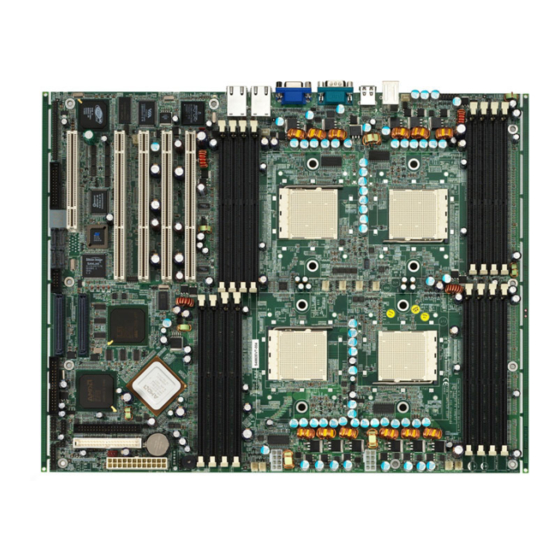
Page 8: Board Image
This picture is representative of the latest board revision available at the time of publishing. The board you receive may or may not look exactly like the above picture. The following page includes details on the vital components of this motherboard. http://www.TYAN.com... -
Page 9: Block Diagram
2.01 – Block Diagram S4882 Thunder K8QS Pro Block Diagram http://www.TYAN.com... -
Page 10: Board Parts, Jumpers And Connectors
2.02 – Board Parts, Jumpers and Connectors This diagram is representative of the latest board revision available at the time of publishing. The board you receive may not look exactly like the above diagram. http://www.TYAN.com... - Page 11 Gigabit LAN1 LED Header See Section 2.13 for pinout CPU Fan Connectors See Section 2.14 Chassis Fan Connectors See Section 2.15 SCSI Zero Channel RAID See Section 2.16 (ZCR) PCI Slot (PCI-X Slot4) Parallel Header(LPT CONN) See Section 2.17 http://www.TYAN.com...
-
Page 12: Front Panel Connector (J6)
To indicate the location of pin-1 To indicate the location of pin-1 2.03 – Front Panel Connector (J6) Function Function PWR LED+ LED+ PWR LED- LED- Reset Button - Button+ Reset PWR Button- Button + VDD_5_R VDD_5_RU IRRX BUZZER IRTX _SPKR SPKR http://www.TYAN.com... -
Page 13: Clear Cmos Jumper (J8)
CMOS Put jumper cap back to Pin_1 and Pin_2 (default setting) Reconnect power & power on system 2.05 – SMBus Connector (J11) Pin_1 Pin_1: Pin_2: Pin_3: Pin_4 SMBUSD_0 SMBUSC_0 : NC Use this connector to connect external SMBUS devices http://www.TYAN.com... -
Page 14: Usb 1.1 Header (J12,J68)
2.06 – USB 1.1 Header (J12,J68) Signal Signal Description Description USB DATA- USB DATA- USB DATA+ USB DATA+ 2.07 – Case Open Detect Connector (J19) Pin-2 PIN2 Pin-1 PIN1 INTRUDUER_L For use with chassis that support this feature http://www.TYAN.com... -
Page 15: Serial Port Internal Header (J23)
Note: If 2 PCI-X cards are mounted, we advise to choose configuration to 100MHz, and if PCI cards are mounted, we advise to choose configuration to PCI Mode. 133MHz Open Open (default) 100MHz Open Closed PCI Mode Closed * *denotes open or closed http://www.TYAN.com... -
Page 16: Pci-X Speed Select Jumper (J41, J43)
PCI Mode. 100MHz Open Open 66MHz Open Closed (default) PCI Mode Closed * *denotes open or closed 2.11 – Keyboard Lock Jumper (J42) OPEN (Default) To enable PS/2 keyboard CLOSED To disable PS/2 keyboard http://www.TYAN.com... -
Page 17: Gigabit Lan2 Led Header (J79)
2. 12– Gigabit LAN2 LED Header (J79) Pin_1:LAN LED+ PIN-1 PIN-2 Pin_2:LAN LED- 2. 13– Gigabit LAN1 LED Header (J80) Pin_1:LAN LED+ PIN_1 PIN_2 Pin_2:LAN LED- Use this 2-pin header to connect external LAN LED. http://www.TYAN.com... -
Page 18: Cpu Fan Connectors (J47, J5, J48, J44)
2.15– Chassis FAN Connectors (J71, J70, J73, J72, J4, J3, J9, J74, J75) Rated Function Description (Maximu FAN1 Read 2.0 A FAN2 Read 2.5 A FAN3 Read 2.5 A FAN4 Read 1.6 A FAN5 Read 2.5 A FAN6 Read 1.2 A FAN7 Read 1.6 A FAN8 1.2 A FAN9 1.2 A http://www.TYAN.com... -
Page 19: Scsi Zcr Slot
This slot is capable of accepting the LSI Zero Channel RAID card* Note: It supports LSI 2032L Zero Channel RAID Card. 2.17– Parallel Header ( LPT CONN ) Signal Signal Configuration Configuration AUTFD DATA0 ERROR DATA1 INIT DATA2 SLIN DATA3 DATA4 DATA5 DATA6 DATA7 BUSY SLCT http://www.TYAN.com... -
Page 20: Oem Reserved Connectors And Jumpers
When using a single processor only CPU0 memory banks are addressable. TYAN is not liable for damage as a result of operating an unsupported configuration. The diagram is provided as a visual guide to help you install socket processors and may not be an exact representation of the processors you have. -
Page 21: Heatsink Retention Frame Installation
The following diagram will illustrate how to install the most common CPU back plates: 1. Mounting screws 2. Heatsink retention frame 3. CPU socket 4. Motherboard PCB 5. Adhesive insulator material 6. Backplate assembly NOTE: Please see next section for specific instructions on how to install mounting bracket. http://www.TYAN.com... -
Page 22: Thermal Interface Material
CPU lid (applying too much will actually reduce the cooling). Always check with the manufacturer of the heatsink & processor to NOTE ensure the Thermal Interface material is compatible with the processor & meets the manufacturer’s warranty requirements http://www.TYAN.com... -
Page 23: Heatsink Installation Procedures
2. After tightening screws secure metal clip to plastic retention bracket center tab. Repeat for on other side of heatsink. 3. After securing metal clip to plastic retention bracket center tab, push down on plastic clip to lock plastic clip to side tab. http://www.TYAN.com... -
Page 24: Finishing Installing The Heatsink
(which should already be attached to the heatsink) to the motherboard. The following diagram illustrates how to connect fans onto the motherboard. Once you have finished installing all the fans you can connect your drives (hard drives, CD-ROM drives, etc.) to your motherboard. http://www.TYAN.com... -
Page 25: Tips On Installing Motherboard In Chassis
If there are any studs missing, you will know right away since the motherboard will not be able to be securely installed. Thunder K8QS Pro S4882 Mounting Hole Placement http://www.TYAN.com... - Page 26 Some chassis’ include plastic studs instead of metal. Although the plastic studs are usable, TYAN recommends using metal studs with screws that will fasten the motherboard more securely in place. Below is a chart detailing what the most common motherboard studs look like and how they should be installed.
-
Page 27: Installing The Memory
/ PC1600 DDR SDRAM memory modules are supported • All installed memory will be automatically detected • The Thunder K8QS Pro supports up to 32GB.* * Not validated at the time of print; subject to change. Modifying the memory configuration for a S4882 is fairly simple by following a few basic steps. - Page 28 Bank 0, low 64, even DIMM1 Not Used Bank 0, high 64 Bank 0, high 64, even DIMM2 Bank 1 Bank 1, low 64 Bank 0, low 64, DIMM3 Not Used Bank 1, high 64 Bank 0, high 64, http://www.TYAN.com...
- Page 29 To remove the memory module, simply push the latches outwards until the memory module pops up. Then remove the module. YOU MUST ALWAYS unplug the power connector from the NOTE motherboard before performing system hardware changes. Otherwise you may damage the board and/or expansion device. http://www.TYAN.com...
-
Page 30: Attaching Drive Cables
2.26 – Attaching Drive Cables Attaching the IDE drive cable is simple. These cables are “keyed” to only allow them to be connected in the correct manner. TYAN motherboards have two on-board IDE channels, each supporting two drives. The black connector designates the Primary channel, while the white connector designates the Secondary channel. - Page 31 Connections for these drives are also very simple. There is no need to set Master/Slave jumpers on SATA drives. Tyan has supplied four SATA cables and two SATA power adapter. If you are in need of other cables or power adapters please contact your place of purchase.
-
Page 32: Installing Add-In Cards
YOU MUST ALWAYS unplug the power connector from the NOTE motherboard before performing system hardware changes. Otherwise you may damage the board and/or expansion device. http://www.TYAN.com... -
Page 33: Pci Riser Cards
2.28 – PCI Riser Cards Supported on Thunder K8QS Pro S4882 Model Number M2037 M2043 M2043X M2044 What speeds can 66MHz 66MHz 66MHz ALL SPEEDS support 33MHz 33MHz 33MHz Form Factor What kind of Gold 3.3V and 5V 3.3V and 5V 3.3V and 5V... -
Page 34: Connecting External Devices
The following diagram will detail the ATX port stack for the following board: 2.30– Installing the Power Supply There are three power connectors on your Thunder K8QS Pro. Tyan recommends that you have an EPS12V power supply that has one 24-pin and two 8-pin power connectors. -
Page 35: Finishing Up
In the rare circumstance that you have experienced difficulty, you can find help by asking your vendor for assistance. If they are not available for assistance, please find setup information and documentation online at our website or by calling your vendor’s support line. http://www.TYAN.com... - Page 36 http://www.TYAN.com...
-
Page 37: Chapter 3: Bios
To display a sub-menu (A pointer “ ” marks all sub menus) Use the arrow keys to move the cursor to the sub menu you want. Then press <Enter>. 3.10 – BIOS Menu Bar The menu bar at the top of the windows lists these selections: http://www.TYAN.com... -
Page 38: Bios Legend Bar
Legacy Diskette A: [1.44/1.25MB 3”] selects field Primary Master [None] Primary Slave [None] Secondary Master [None] Secondary Slave [None] HDD Post Write Buffer: [Enabled] Large Disk Access Mode: [DOS] Extended Memory Testing [Just zero it] Boot Summary Screen: [Disabled] http://www.TYAN.com... - Page 39 Enabled This setting enables or disables Disabled 32 bit IDE data transfers. Transfer Mode: Display the Transfer Mode of the plugged IDE device Ultra DMA Mode Display the Ultra DMA which the IDE device support 3.3.5 –Extended Memory Testing http://www.TYAN.com...
-
Page 40: Bios Advanced Menu
Exit Item Specific Help Hardware Monitor SMBIOS(DMI) Event Logging <Tab>, <Shift-Tab>, or Console Redirection <Enter> selects field Installed O/S: [Other] Reset Configuration Data: [No] Multiprocessor Specification: [1.4] Use PCI Interrupt Entries in MP Table: [Yes] ACPI SRAT Table: [Enable] http://www.TYAN.com... - Page 41 Select ‘Enable’ to allow logging of Disable DMI events. ECC Event Logging Enable Select ‘Enable’ to allow logging of ECC events. Disable Mark DMI events as read Press Enter to mark all DMI events in the event log as read. http://www.TYAN.com...
- Page 42 This setting erases all configuration data in a section of memory for ESCD (Extended System Configuration Data) which stores the configuration settings for non-PnP plug-in devices. Select Yes when required to restore the manufacturer's defaults 3.4.5 – Multiprocessor Specification http://www.TYAN.com...
- Page 43 3.4.11 – 4GB Memory Hole Adjust Feature Option Description 4GB Memory Hole Adjust Auto Auto – Adjust the memory hole size Manual automatically according to the memory space used by PCI devices Manual – Memory hole size is determined manually http://www.TYAN.com...
- Page 44 Set the rate of background scrubbing for 40ns/80ns/ L2 cache lines 160ns/320n s/640ns/1.2 8us/2.56us Dram ECC Scrub CTL Disable Set the rate of BACKGROUND scrubbing 1.31ms for Dram. /2.62ms/5.2 4ms/10.49 ms/20.97m s/42ms/84 Speculative TLB Reload Enable Enable / Disable Speculative TLB Reload Disable http://www.TYAN.com...
- Page 45 DOS or UNIX Onboard PCI IDE Disable Enable the integrated local bus Primary IDE adapter Secondary Both Serial Port A Enable Configure serial port Disable AUTO Serial Port A Base I/O Address 3F8/2F8/3E8/ Serial Port A Interrupt IRQ4 / IRQ3 http://www.TYAN.com...
- Page 46 Reserve specific IRQs for use by PCI/PNP IRQ Exclusion legacy ISA devices. Reserve specific upper memory PCI/PNP UMB Exclusions blocks for use by legacy ISA devices. ﹡ Enable Broadcom LAN Port 2 PXE may lead to option ROM overflow. http://www.TYAN.com...
-
Page 47: Bios Security Menu
<Tab>, <Shift-Tab>, or Resume Time: [00:00:00] <Enter> selects field Resume Date: [00/00/0000] Intruder Support [Disabled] After Power Failure: [Last State] ↑/↓Select Item F1 Help -/+ Change Values F9 Setup Defaults ESC Exit ←/→Select Menu Enter Select Sub-Menu F10 Save and Exit http://www.TYAN.com... -
Page 48: Bios Boot Menu
Item Specific Help CD-ROM Drive +Removable Devices +Hard Drive Network Boot MBA V6.1.2 SLOT 0248 MBA V6.1.2 SLOT 0249 ↑/↓Select Item F1 Help -/+ Change Values F9 Setup Defaults ESC Exit ←/→Select Menu Enter Select Sub-Menu F10 Save and Exit http://www.TYAN.com... - Page 49 Use this option when system CMOS values have been corrupted or modified incorrectly. 3.8.4 – Discard Changes Use this option to restore all new setup values that you have made but not saved into CMOS. 3.8.5 – Save Changes Use this option to store all new setup values into CMOS. http://www.TYAN.com...
-
Page 50: Chapter 4: Diagnostics
(2) Graphics initialization failed Before contacting your vendor or Tyan Technical Support, be sure that you note as much as you can about the beep code length and order that you experience. Also, be ready with information regarding add-in cards, drives and O/S to speed the support process and come to a quicker solution. -
Page 51: Appendix I: Glossary
CPU (similar to DMA channels). Cache: a temporary storage area for data that will be needed often by an application. Using a cache lowers data access times since the information is stored in SRAM instead http://www.TYAN.com... - Page 52 EEPROM (Electrically Erasable Programmable ROM): also called Flash BIOS, it is a ROM chip which can, unlike normal ROM, be updated. This allows you to keep up with changes in the BIOS programs without having to buy a new chip. TYAN’s BIOS updates can be found at http://www.tyan.com ESCD (Extended System Configuration Data): a format for storing information about Plug-n-Play devices in the system BIOS.
- Page 53 IDE drives. These modes use the CPU for data transfer (in contrast, DMA channels do not). PCI refers to the type of bus used by these modes to communicate with the CPU. PCI-to-PCI bridge: allows you to connect multiple PCI devices onto one PCI slot. http://www.TYAN.com...
- Page 54 AcceleRAID 150, 200 or 250, to implement RAID on a system board-embedded SCSI bus or a set of SCSI busses. SISL: SCSI Interrupt Steering Logic ( LSI ) (only on LSI SCSI boards) Sleep/Suspend mode: in this mode, all devices except the CPU shut down. http://www.TYAN.com...
- Page 55 CPUs without damaging the sensitive CPU pins. The CPU is lightly placed in an open ZIF socket, and a lever is pulled down. This shifts the processor over and down, guiding it into the board and locking it into place. http://www.TYAN.com...
-
Page 56: Appendix Ii: Bios Post Code
Display possible high address for UMB high byte of memory bus recovery Test CPU bus-clock frequency Display error messages Initialize Phoenix Dispatch Manager Check for configuration errors Warm start shut down Check for keyboard errors Shadow system BIOS ROM Set up hardware interrupt vectors http://www.TYAN.com... - Page 57 Scan for F2 key stroke Initialize interrupt vectors Enter SETUP Initialize Run Time Clock Clear Boot flag Initialize video Check for errors Initialize System Management Mode POST done - prepare to boot Output one beep before boot operating system http://www.TYAN.com...
- Page 58 Code Beeps / Description Code Beeps / Description One short beep before boot Boot to Mini DOS Terminate QuietBoot (optional) Clear Huge Segment Check password (optional) Boot to Full DOS Prepare Boot http://www.TYAN.com...
-
Page 59: Technical Support
Return Merchandise Authorization (RMA) number. The RMA number should be prominently displayed on the outside of the shipping carton and the package should be mailed prepaid. TYAN will pay to have the board shipped back to you. - Page 60 Danger of explosion if battery is incorrectly replaced. Replace only with the same or equivalent type recommended by manufacturer. Dispose of used battery according to manufacturer instructions and in accordance with your local regulations. Document #: D1607-100 http://www.TYAN.com...