Table of Contents
Advertisement
Quick Links
Advertisement
Table of Contents

Related Manuals for eMachines EL1358


Summary of Contents for eMachines EL1358
- Page 1 EL1358 Service Guide PRINTED IN TAIWAN...
-
Page 2: Revision History
Revision History Refer to the table below for changes made on this version of the EL1358 Desktop Computer Service Guide. Date Chapter Updates EL1358 Service Guide... - Page 3 Acer is a registered trademark of Acer Incorporated. Other brand and product names are trademarks and/or registered trademarks of their respective holders. EL1358 Service Guide...
- Page 4 Alerts you to any physical risk or system damage that might result from doing or not doing specific actions. CAUTION Gives precautionary measures to avoid possible hardware or software problems. IMPORTANT Reminds you to do specific actions relevant to the accomplishment of procedures. EL1358 Service Guide...
-
Page 5: Fru Information
FRU list of this printed service guide. You MUST use the list provided by your regional Acer office to order FRU parts for repair and service of customer machines. EL1358 Service Guide... - Page 6 EL1358 Service Guide...
-
Page 7: Table Of Contents
EL1358 FRU List ........ - Page 8 Table of Contents BIOS ............. . .82 Technical Specifications ...............
-
Page 9: Features And Specifications
Chapter 1 Features and Specifications This chapter lists the features and specifications of the EL1358 computer. NOTE The items listed in this section are for reference only. The exact configuration of your PC depends on the model purchased. Refer to the FRU list chapter on page 74 for a detailed list of models supported by each hardware component. -
Page 10: Audio
– PS/2 keyboard and mouse ports – External display (VGA) port – USB ports (four) – Ethernet jack (RJ45) – Microphone, line-out, and line-in jacks – Kensington lock – Key lock LED display and buttons • Power LED • Power button EL1358 Service Guide... -
Page 11: Physical Specifications
5.382 kg. Mainboard form factor microATX (µATX) Mainboard dimensions (W × H) 244 × 200 mm Environmental Requirements Aspect Description Operating temperature 5 to 35 °C (41 to 95 °F) Operating humidity 15% to 80% RH non-condensing EL1358 Service Guide... -
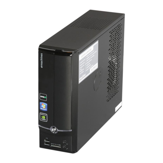
Page 12: System Tour
System Tour The pictures and tables in this section illustrate the physical outlook of the computer. Front View Component Optical drive eject button Optical drive cover Power button/indicator Microphone-in jack Headphone jack Multi-in-1 card reader USB 2.0 ports EL1358 Service Guide... -
Page 13: Rear View
Rear View Component Line-in jack LAN connector Key lock Kensington lock Power connector Fan aperture PS/2 keyboard connector PS/2 mouse connector Monitor port USB 2.0 ports Microphone jack Line-out jack Expansion slots EL1358 Service Guide... - Page 14 EL1358 Service Guide...
-
Page 15: System Utilities
(BT1) may be defective. In this case, the system cannot retain configuration values in CMOS. Replace the RTC battery with a new one. NOTE For ease of reading, CMOS Setup Utility will be simply referred to as “Setup” or “Setup Utility” in this Service Guide. EL1358 Service Guide... -
Page 16: Accessing The Setup Utility
Some options (marked with a ) lead to submenus that enable you to change the values for the option. Use the Up/Down/Left/Right arrow keys to scroll through the items in the submenu EL1358 Service Guide... -
Page 17: Navigating Through The Setup Utility
• The screenshots used in this section are for illustration only. The values displayed may not be the same as those in your computer. • In the descriptive tables following each of the menu screen illustrations, settings in boldface are the default and suggested settings. EL1358 Service Guide... -
Page 18: Product Information
Official model name of the computer. System Serial Number System serial number. System BIOS Version Current system BIOS version BIOS Release Date Date when the CMOS setup utility was released. Asset Tag Number System asset tag number EL1358 Service Guide... -
Page 19: Standard Cmos Features
• All Errors - Any error detected will pause the system. • No Errors - BIOS will ignore any errors detected during POST • All, but Keyboard - If a keyboard error is detected, BIOS will pause the system. EL1358 Service Guide... -
Page 20: Advanced Bios Features
Enabled Protection or hard disk partition table, there will be no warning message. Disabled USB Beep Message Select whether to allow the BIOS to emit error beeps or display Enabled error messages during USB device enumeration. Disabled EL1358 Service Guide... -
Page 21: Advanced Chipset Features
PCIE, Onboard, then PCI. UMA Frame Buffer Size When a GPU expansion board is installed, you can select how the Auto system video memory (frame buffer) is allotted. 32 MB 64 MB 128 MB 256 MB EL1358 Service Guide... -
Page 22: Integrated Peripherals
Onboard Audio Controller Enables or disables the onboard audio controller. Enabled Disabled Onboard LAN Controller Enables or disables the onboard LAN controller. Enabled Disabled Onboard LAN Option ROM Enables or disables the onboard LAN option ROM function. Enabled Disabled EL1358 Service Guide... -
Page 23: Power Management Setup
LAN controller received a network Disabled message. Wake Up by PS/2 KB/ Enables or disables the system to wake up from a power-saving Enabled Mouse mode when a PS/2 keyboard or mouse is used. Disabled EL1358 Service Guide... -
Page 24: Pc Health Status
PC Health Status Field Description Value CPU Temperature These items lets you monitor the parameters for critical voltages, temperatures and System Temperature fan speeds. CPU Fan Speed System Fan Speed CPU Core +1.2V +3.30V +5.00V +12.0V 5VSB VBAT EL1358 Service Guide... - Page 25 Note: Remember to disable the Spread Spectrum feature if you are overclocking. A slight jitter can introduce a temporary boost in clock speed causing the overclocked processor to lock up. EL1358 Service Guide...
-
Page 26: Bios Security Features
Only shaded blocks representing each typed character are visible. Retype the password to verify the first entry, then press Enter. You will be prompted to save the new password. Press Enter. Press F10 to save the password and close the Setup Utility. EL1358 Service Guide... -
Page 27: Load Default Settings
Select OK, then press Enter. Press F10 to save the changes you made and close the Setup Utility. Save & Exit Setup Execute this menu to save the changes made and closes the Setup Utility. Keyboard shortcut: F10 EL1358 Service Guide... -
Page 28: Exit Without Saving
Exit Without Saving Execute this menu to closes the Setup Utility without making any changes. EL1358 Service Guide... -
Page 29: System Disassembly
Turn off the power to the computer and all peripherals. Unplug the power cord from the computer. Unplug the network cable and all connected peripheral devices from the computer. Place the computer on a flat, steady surface. EL1358 Service Guide... -
Page 30: Disassembly Procedures
Remove the two screws located on the rear edge of the side panel. Slide the panel back about 2.5 cm (1.0 in) to release it from the chassis notches, then detach the panel from the chassis. Put the side panel aside for reinstallation later. EL1358 Service Guide... -
Page 31: Removing The Front Bezel
Removing the Front Bezel Release the front bezel retention tabs from the chassis interior. Pull the front bezel away from the chassis. Detach the front bezel. EL1358 Service Guide... -
Page 32: Removing The Heat Sink Fan Assembly
Lift the heat sink fan assembly away from the mainboard. Lay down the heat sink fan assembly, in an upright position, on top of the optical drive, as shown below, then disconnect the fan cable from the mainboard. EL1358 Service Guide... -
Page 33: Removing The Processor
Pull the load lever to the fully open, upright position (2). Pull out the processor from the socket. IMPORTANT:If you are going to install a new processor, note the arrow on the corner to make sure the processor is properly oriented over the socket. EL1358 Service Guide... -
Page 34: Removing The Hdd-Odd Bracket
Removing the HDD-ODD Bracket Remove the two screws that secure the HDD-ODD bracket to the chassis. Lift the bracket up. EL1358 Service Guide... -
Page 35: Removing The Optical Drive And The Hard Disk Drive
Removing the Optical Drive and the Hard Disk Drive Disconnect the SATA and power cables from the rear of the optical drive. Disconnect the other end of the SATA cable from the mainboard. EL1358 Service Guide... - Page 36 Disconnect the SATA and power cables from the rear of the hard disk drive. Disconnect the other end of the SATA cable from the mainboard. EL1358 Service Guide...
- Page 37 Remove the screws that secure the optical drive to the HDD-ODD bracket. Pull the optical drive out of the drive bay. EL1358 Service Guide...
- Page 38 Remove the four screws that secure the hard disk drive to the HDD bracket. Slide the hard disk drive out of the bracket. EL1358 Service Guide...
-
Page 39: Removing The Expansion Boards
Gently pull up the expansion board (1), move it slightly to the left and remove (2) from the slot. Remove the screw from the expansion board bracket opposite the PCIEX2 slot. Gently pull up the expansion board (1), move it slightly to the left and remove (2) from the slot. EL1358 Service Guide... -
Page 40: Removing The Memory Modules
Disconnect the 4-pin and the 24-pin ATX power supply cables from its mainboard connector. Squeeze on the retaining latch (a) attached to the cable end of the connector. Grasp the cable end of the connector and pull it straight up (b). EL1358 Service Guide... - Page 41 Remove the screw that secures the power supply to the chassis. Remove the two screws that secure the power supply to the rear panel. EL1358 Service Guide...
- Page 42 Push the power supply module toward the front. Tilt the power supply module slightly to the right and lift it out of the chassis. EL1358 Service Guide...
-
Page 43: Removing The Front I/O And Card Reader Assembly
Removing the Front I/O and Card Reader Assembly Disconnect the power button/LED, front I/O and card reader cables from their mainboard connectors. Open the plastic clip (1) and release the cables from the metal clip (2) in the direction indicated. EL1358 Service Guide... - Page 44 Detach the cables from the card. Remove the cables. Remove the screw that secures the bracket to the chassis. EL1358 Service Guide...
- Page 45 Pull the bracket out from the chassis. Remove the two screws that secure the front I/O and card reader assembly to the bracket. EL1358 Service Guide...
- Page 46 Remove the front I/O and card reader assembly from the bracket. EL1358 Service Guide...
-
Page 47: Removing The Mainboard
Remove the four screws that secure the mainboard to the chassis. Note:Circuit boards >10 cm2 has been highlighted with the yellow rectangle as above image shows. Please detach the Circuit boards and follow local regulations for disposal. EL1358 Service Guide... - Page 48 Lift the board from the chassis. Remove the RTC battery. Note:RTC battery has been highlighted with the yellow circle as above image shows. Please detach the RTC battery and follow local regulations for disposal. EL1358 Service Guide...
-
Page 49: Troubleshooting
Make sure that there is no point of contact in the system that can cause a power short. If the cause of the failure is still can not be determined, perform the “System Internal Inspection” procedure described on the next page. EL1358 Service Guide... -
Page 50: Checkpoints
If memory sizing module not executed, start memory refresh and do memory sizing in bootblock code. Do additional chipset initialization. Re-enable CACHE. Verify that flat mode is enabled. Test base 512 KB memory. Adjust policies and cache first 8 MB. Set stack. EL1358 Service Guide... -
Page 51: Boot Block Recovery Code Checkpoints
The recovery file size does not equal the found flash part size. Erase the flash part. Program the flash part. The flash has been updated successfully. Make flash write disabled. Disable ATAPI hardware. Restore CPUID value back into register. Give control to F000 ROM at F000:FFF0h. EL1358 Service Guide... -
Page 52: Post Code Checkpoints
USB controllers are initialized at this point. Initializes DMAC-1 & DMAC-2. Initialize RTC date/time. Test for total memory installed in the system. Also, Check for DEL or ESC keys to limit memory test. Display total memory in the system. EL1358 Service Guide... - Page 53 Wait for user input at config display if needed. Uninstall POST INT1Ch vector and INT09h vector. Deinitializes the ADM module. Prepare BBS for Int 19 boot. End of POST initialization of chipset registers. Save system context for ACPI. Passes control to OS Loader (typically INT19h). EL1358 Service Guide...
-
Page 54: Post Error Indicators
Follow the instructions on the screen. It is recommended that you correct the error before proceeding, even if the computer appears to boot successfully. IMPORTANT If your system fails after you make changes in the Setup menus, reboot the computer, enter Setup again and load Setup defaults to correct the error. EL1358 Service Guide... - Page 55 BIOS could not find a bootable device in the system and/or removable proper boot device or media drive does not contain media. Insert boot media in selected boot device NO ROM BASIC This message occurs on some systems when no bootable device can be detected. EL1358 Service Guide...
-
Page 56: Storage Device
3rd Master Drive - The IDE/ATAPI device configured as Master in the 3rd IDE controller failed an ATAPI Incompatible ATAPI compatibility test. This message is typically displayed when the BIOS is trying to detect and configure IDE/ATAPI devices in POST. EL1358 Service Guide... - Page 57 A S.M.A.R.T. capable hard disk sends this message when it detects an imminent and Status BAD failure. This message can be reported by an ATAPI device using the S.M.A.R.T. error reporting standard. S.M.A.R.T. failure messages may indicate the need to replace the hard disk. EL1358 Service Guide...
-
Page 58: System Configuration
BIOS POST could not initialize the Master Interrupt Controller. This may indicate a error problem with system hardware. Interrupt Controller-2 BIOS POST could not initialize the Slave Interrupt Controller. This may indicate a problem with system hardware. error EL1358 Service Guide... - Page 59 This message is displayed when ADM module is not present in the AMIBIOS8 Error code = 004Ah ROM. Unknown BIOS error. This message is displayed when language module is not present in the AMIBIOS8 Error code = 004Bh ROM. Floppy Controller Error in initializing legacy Floppy Controller. Failure EL1358 Service Guide...
- Page 60 Blinking cursor only; system does not work. • IDE drive connection/cables • IDE disk drives • See “Undetermined Problems”. • Mainboard NOTE Ensure the memory modules are installed properly and the contact leads are clean before diagnosing any system problems. EL1358 Service Guide...
- Page 61 • Speaker power/connection/cable. • CD/DVD-ROM drive. NOTE Make sure the optical disc drive is configured correctly in CMOS Setup, the cable/jumper are set correctly and the drive’s optical lens is clean before diagnosing any optical drive problems. EL1358 Service Guide...
- Page 62 • Video adapter card • Missing, broken, or incorrect characters • Mainboard • Blank monitor (dark) • Blank monitor (bright) • Distorted image • Unreadable monitor Display changing colors. • Monitor signal connection/cable • Video adapter card • Mainboard EL1358 Service Guide...
- Page 63 Windows98 Start menu does not turn off the • Reload software from Recovery CD. system. (Only pressing power button can turn off the system). No system power, or power supply fan is • Power supply not running. • Mainboard EL1358 Service Guide...
-
Page 64: Beep Codes
If the problem does not recur, reconnect the removed devices one at a time until you find the failed FRU. If the problem persists, replace the mainboard, and then LCD assembly (one at a time). Do not replace a non-defective FRU. EL1358 Service Guide... -
Page 65: Bios Recovery
Press Delete to run the CMOS Setup Utility. Press F9 to load the system default settings. Select Ok, then press Enter. Press F9 to save the default settings and close the Setup utility. Select Ok, then press Enter. EL1358 Service Guide... -
Page 66: Bios Update
Press Delete to run the CMOS Setup Utility. Press F9 to load the system default settings. Select Ok, then press Enter. Press F9 to save the default settings and close the Setup utility. 10. Select Ok, then press Enter. EL1358 Service Guide... -
Page 67: Updating The Bios In Windows Mode
Press the power button to turn on the computer. Click Start | Command Prompt | Run as administrator. Perform the steps below if your computer is running 32-bit Windows. Key in 'cd wintool\32'. (Go to BIOS path like "D:\WinTool\32") Key in 'flash1M.bat' or 'flash1M'. EL1358 Service Guide... - Page 68 Press Enter to flash the system BIOS. Perform the steps below if your computer is running 64-bit Windows. Key in 'cd wintool\64'. (Go to BIOS path like "D:\WinTool\64") Key in 'flash1M.bat' or 'flash1M'. EL1358 Service Guide...
- Page 69 Press Delete to run the CMOS Setup Utility. Press F9 to load the system default settings. Select Ok, then press Enter. Press F9 to save the default settings and close the Setup utility. 10. Select Ok, then press Enter. EL1358 Service Guide...
-
Page 70: Clearing Cmos
14. During POST, press Delete to access the Setup Utility. 15. Press F9 to load the system default values. 16. Press F10 to save the changes you made and close the Setup Utility. EL1358 Service Guide... -
Page 71: System Architecture
Chapter 5 System Architecture This chapter shows the system block diagram and board layout. Block Diagram The core subsystems of the computer are depicted in the following block diagram. EL1358 Service Guide... -
Page 72: Mainboard Layout
LEDH1 12-pin power cable header PWR1 ATX 4-pin connector USBF 2-3 Front panel USB header KBMSCONN1 Keyboard and mouse connectors USBF 1 Front panel card reader header JBIOS1 Clear CMOS jumper AUDIOF1 Front panel audio jack header EL1358 Service Guide... -
Page 73: Jumper Setting
1 and 2 to close or short the jumper. Place the jumper cap on pins 2 and 3 to open or clear the jumper. Jumper Type Description Setting (default) JBIOS1 3-pin Clear CMOS 1-2: Close (default) 2-3: Open Before clearing the CMOS, make sure to turn off the system. EL1358 Service Guide... -
Page 74: Internal Header Pin Definition
3: USB2_XN 4: USB4_XN 5: USB2_XP 6: USB4_XP 7:GND 8: GND 9: KEY 10: GND FRONT AUDIO HEADER 1: PORT-F_L 2: AUGND 3: PORT-F_R 4: FRONT_AUD_DET 5: PORT-E_R 6: MIC2_JD 7: AUGND 8: KEY 9: PORT-E_L 10: LINE2_JD EL1358 Service Guide... -
Page 75: Connector Pin Definition
3: SATA1_TX_N 4: GND 5: SATA1_RX_N 6: SATA1_RX_P 7: GND ATX_POWER CONN 1:VCC3 13:VCC3 2:VCC3 14:-12V 3: GND 15:GND 4:VCC 16:ATX_PSON_L 5:GND 17:GND 6:VCC 18:GND 7:GND 19:GND 8:ATX_PWRGD 20:NC 9:5VSB 21VCC 10:+12V 22:VCC 11:+12V 23:VCC 12:VCC3 24:GND EL1358 Service Guide... -
Page 76: Connecting Optional Devices
These connectors are used to support the new Serial ATA devices for the highest datatransfer rates (3.0 Gb/s), simpler disk drive cabling and easier PC assembly. It elimi-nates limitations of the current Parallel ATA interface. But maintains register com-patibility and software compatibility with Parallel ATA. Signal Name Signal Name Ground Ground Ground EL1358 Service Guide... - Page 77 Front Panel USB Power USBPWR Front Panel USB Power USB_FP_P0- USB Port 0 Negative Signal USB_FP_P1- USB Port 1 Negative Signal USB_FP_P0+ USB Port 0 Positive Signal USB_FP_P1+ USB Port 1 Positive Signal Ground Ground No pin USB_FP_OC0 Overcurrent signal EL1358 Service Guide...
-
Page 78: Connecting Case Components
Connect the standard power supply connector to PWR2. Connect the case switches and indicator LEDs to the LEDH1. Connect the auxiliary case power supply connector to PWR1. CPUFAN1: CPU Cooling Fan Power Connector Signal Name Function System ground +12V Power +12V Sense Sensor EL1358 Service Guide... -
Page 79: Front Panel Header
*MSG LED (+) HDD_LEDN Hard disk LED (-) GLED1 *MSG LED (-) Reset Switch (-) PWRSW Power Switch (+) HWRST_L Reset Switch (+) Power Switch (-) F_PANEL_DET Reserved No pin Reserved Reset Switch (+) Reserved F_LAN_LED Reset Switch (+) EL1358 Service Guide... - Page 80 EL1358 Service Guide...
-
Page 81: Field Replaceable Unit (Fru) List
Chapter 6 Field Replaceable Unit (FRU) List This chapter gives you the FRU (Field Replaceable Unit) listing of the EL1358 computer global configurations. Refer to this list when ordering for repair parts or for RMA (Return Merchandise Authorization). IMPORTANT When ordering FRU parts, check the most up-to-date information available on your regional web or channel. -
Page 82: El1358 Fru List
EL1358 FRU List ACER_EL1358_W_EMANALO(NO:91.3FJ01.001G) Category Part Name Description OEM Part No. BOARDS FRONT IO BOARD USB 2.0 2 F-IO BD USB 2.0 2 USB 55.NCM01.001 USB PORT 2 AUDIO PORT W/ PORT 2 AUDIO PORT O CARD READER FRONT IO & CARD READER CARD READER 6 IN 1 55.NCM01.002... - Page 83 POWER CORD 250V 3PIN POWER CORD FOR 27.01518.I51 1830MM BLACK THAILAND THAILAND 1830MM POWER CORD 250V 3PIN POWER CORD 27.03118.031 1800MM UK 1800MM 250V UK CASE/COVER/BRACKET ASSEMBLY LOWER CASE W/ ASSY LCASE-ASM 60.NCM01.002 ASSEMBLY LED SWITCH CABLE BOXER EM EL1358 Service Guide...
- Page 84 IC CPU ATHLON II X2 KC.AE202.240 AM3+ 2.8G 2X1M 4000 940 240E 2.8G 45W C-2 DUAL CORE CPU AMD ATHLON II X3 400E IC CPU ATHLON II X3 KC.AE202.400 2.2GHZ 1.5M L2 CACHE 45W 400E 2.2GH RANA ATHIIX3400E EL1358 Service Guide...
- Page 85 65W HEKA PHNMII700E CPU AMD PHENOMII X 3 705E IC CPU PHENOMII X 3 KC.PE202.705 2.5GHZ 7.5M TOTAL CACHE 705E 2.5GH 65W HEKA PHNMII705E CPU AMD SEMPRON 140 2.7G IC CPU SEMPRON 140 KC.SMP02.140 45W PGA 2.7G 45W PGA EL1358 Service Guide...
- Page 86 SATA III 16MB LF F/W:JC45 HDD WD 3.5" 7200RPM 500GB HDD 500GB 3.5" WD KH.50008.022 WD5000AAKX-221CA0(XL500- WD5000AAKX-221CA0 1D 6G) SATA III 16MB LF F/ 7.2K W:15.01H15 HDD 640GB 3.5" 7200RPM HDD 640GB HGST KH.64007.002 SATA II 32MB HGST HDS721064CLA332 HDS721064CLA332 JUPITER EL1358 Service Guide...
- Page 87 DIMM 1G KN.1GB0G.024 1333MHZ 1G HMT112U6BFR8C-H9 HMT112U6BFR8C-H9 MEMORY UNIFOSA DDR3 DIMM 1G KN.1GB0H.015 1333MHZ 1G UNB-DIMM GU502203EP0201 GU502203EP0201 LF 128*8 UNB. 0.065UM MEMORY APACER DDR3 DIMM 2G KN.2GB01.025 1333MHZ 2G UNBUFFERED 75.A73C1.G02 DDR3 DIMM W/O ECC 1333MHZ EL1358 Service Guide...
- Page 88 230V DELTA DPS-220UB-1 A 230V DPS-220 POWER SUPPLY 220W PFC SPS 220W EUP PFC PY.22009.010 230V DELTA DPS-220UB-4A 230V DPS-220UB- 4A(NEW) POWER SUPPLY 220W PFC SPS 220W PFC EUP PY.2200B.007 230V LITEON PE-5221-08AP- 230V LITEON P ROHS EUP EL1358 Service Guide...
- Page 89 SCREW FLAT #6-32*3/16 NI SCREW FLAT #6-32*3/ 86.5A5B6.012 16 NI SPEAKER SPEAKER ASI USB 2.0 Q4-08 SPEAKER ASI USB 2.0 SP.10600.019 Q4-08 USB SPEAKER NEOSONICA USB SPK USB NEO 2003B SP.10600.032 NEO 2003 WITH BLACK WITH BLACK COLOR EL1358 Service Guide...
-
Page 90: Processor
Appendix A Technical Specifications This appendix list the technical specifications of the EL1358 hardware components. Processor Common features: • Socket: Socket AM3/AM2+, 938-pin contacts • Package type: 45 nm Item Specification AMD Series Phenom™ II X4 Athlon™ II X4 Athlon™ II X3 Athlon™... -
Page 91: Memory
• WD – WD5000AAKX-221CA0 1000 GB • HGST Jupiter – HDS721010CLA332 • Seagate Pharoah – ST31000524AS • WD – WD10EALX-229BA0 • WD – WD10EADX-22TDHB0 • WD – WD10EARS-22Y5B1 1500 GB • Seagate Brinks – ST31500341AS • WD – WD15EARS-22MVWB EL1358 Service Guide... -
Page 92: Optical Disc Drive
LAN protocol 10/100/1000 Mbit LAN connector type RJ-45 Audio Item Specification Controller • Realtek ALC662 5.1 Channel High Definition Audio Codec Audio jacks • Front panel: Headphone and microphone jacks • Rear panel: Microphone, line-out, and line-in jacks EL1358 Service Guide... -
Page 93: Power Supply Unit
Connectors • 1 x 20/24-pin ATX connector • 1 x 4-pin ATX connector • 2 x SATA connectors Power Management Devices Power Button USB Keyboard/Mouse Disabled Disabled Disabled Disabled Disabled Disabled Disabled Disabled Disabled Disabled Disabled Disabled EL1358 Service Guide... - Page 94 EL1358 Service Guide...
-
Page 95: Index
Index Standard CMOS Features menu 11 connectivity ACPI, see Advanced Configuration Power options 1 Interface 2 specifications 84 Advanced BIOS Features menu 12 connector Advanced Configuration Power Interface LAN 5 specifications 2 power 5 PS/2 keyboard 5 antivirus software 2 PS/2 mouse 5 audio headphone jack 4... - Page 96 configuration utility 7 configuration 11 exploded view 73 remove 27 FRU list 73 specifications 84 specifications 82 troubleshooting 53 troubleshooting 41 OS support 1 HDD, see hard disk drive 1 HDD-ODD bracket remove 26 PC Health Status 16 headphone jack 4 PCB 2 humidity 3 POST, see Power-On Self-Test 44...
- Page 97 audio 84 card reader 84 Ethernet 84 hard disk drive 83 memory 83 optical disc drive 84 power management 85 power supply unit 85 processor 82 system BIOS 82 system chipsets 82 Standard CMOS Features menu 11 supervisor password 18 system architecture 63 system chipsets 82 system date 11...