
Related Manuals for Honeywell HJZTP


Summary of Contents for Honeywell HJZTP
-
Page 1: User Manual
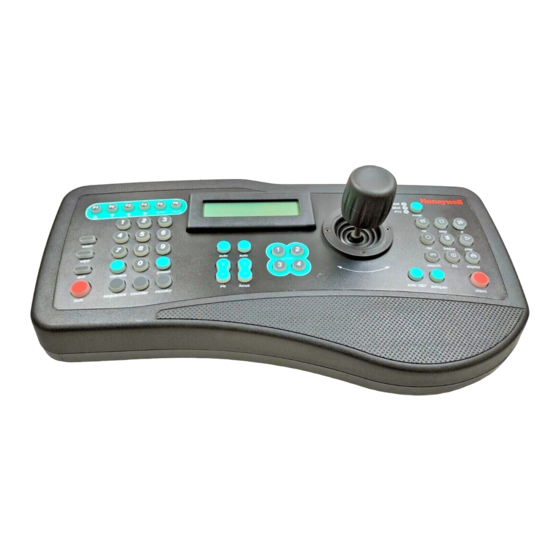
HJZTP/HJZTPX Joystick Controller for PTZ Cameras, DVRs, and Multiplexers User Manual 900.0570 – September 2005 – Rev. 1.01... - Page 2 ISSUE DATE REVISIONS HJZMU001150 March 2005 Initial Release. July 2005 Revised Model # (ECI 2003) 900.0570 1.00 August 2005 Revised Model # Revised cable qty. in package contents and added operation 1.01 September 2005 with KD6i/HD6i in Maxpro Mode (EC03566) Rev.
-
Page 3: Fcc Compliance Statement
Users of the product are responsible for checking and complying with all federal, state and local laws and statutes concerning the monitoring and recording of video and audio signals. Honeywell Video Systems shall not be held responsible for the use of this product in violation of current laws and statutes. -
Page 4: Important Safeguards
IMPORTANT SAFEGUARDS READ INSTRUCTIONS – All safety and operating instructions should be read before the unit is operated. RETAIN INSTRUCTIONS – The safety and operating instructions should be retained for future reference. HEED WARNINGS – All warnings on the unit and in the operating instructions should be adhered FOLLOW INSTRUCTIONS –... - Page 5 IMPORTANT SAFEGUARDS DAMAGE REQUIRING SERVICE – Unplug the unit from the outlet and refer servicing to qualified service personnel under the following conditions: a. When the power-supply cord or plug is damaged. b. If liquid has been spilled, or objects have fallen into the unit. c.
- Page 6 Prior to installation and use of this product, please observe the following cautions and warnings. CAUTION C A U T I O N RISK OF ELECTRIC SHOCK DO NOT OPEN CAUTION: TO REDUCE THE RISK OF ELECTRIC SHOCK, DO NOT REMOVE COVER (OR BACK). NO USER-SERVICEABLE PARTS INSIDE.
-
Page 7: Table Of Contents
TABLE OF CONTENTS SECTION 1: INTRODUCTION ........................ 1 PRODUCT DESCRIPTION ....................... 1 COMPATIBLE PRODUCTS ......................1 PACKAGE CONTENTS ........................2 SECTION 2: INSTALLATION........................3 CONNECTIONS ..........................3 SUPPLIED CABLES ......................... 4 2.2.1 Eight-Way RJ45 Connector to Eight-Way RJ45 Connector ..........4 2.2.2 Eight-Way RJ45 Connector to White/Orange Wire and Orange Wire ...... - Page 8 PICTURE CONTROL ........................22 AUXILIARY MONITOR SELECTION ....................23 CAMERA SELECTION ........................23 MULTIPLEXER SELECTION......................24 SECTION 6: PTZ CONTROL FUNCTIONS WHEN USING HONEYWELL VCL (RAPIDDOME/ORBITER DOME) PROTOCOL......................25 PTZ CAMERA SELECTION CONTROL..................25 PTZ MODE ............................. 25 PAN AND TILT..........................25 TURN 180°............................
-
Page 9: Table Of Contents, Continued
IR Lamps........................33 6.10.6 Auto 180......................... 33 6.10.7 Mimic Tour ........................33 SECTION 7: PTZ CONTROL FUNCTIONS WHEN USING HONEYWELL DIAMOND (KD6/HD6) PROTOCOL........................35 PTZ CAMERA SELECTION (HONEYWELL DIAMOND PROTOCOL) ..........35 PTZ MODE ............................. 35 PAN AND TILT..........................36 ZOOM............................. 36 IRIS 36 FOCUS............................ - Page 10 APPENDIX C: VCL (ORBITER/RAPIDDOME) DATA INPUT ............... 51 APPENDIX D: PASSWORDS........................ 53 LIST OF FIGURES Figure 1: HJZTP Rear Panel ........................3 Figure 2. KBD/AUX/CONTROL CONNECTORS ..................9 Figure 3. POWER CONNECTOR ....................... 10 Figure 4. DOME DAISY CHAIN CONFIGURATION..................5 Figure 5.
-
Page 11: Section 1: Introduction
128 PTZ cameras, 99 DVRs, and 32 multiplexers (using RS485 distribution boxes such as the HDCD8TP). Up to four HJZTP keyboards can be connected together to providing a system controlled by one (1) master keyboard, and three (3) slave keyboards. -
Page 12: Package Contents
Quantity Description HJZTP or HJZTPX Joystick Controller HJZMU001150 User Manual 120 VAC to 12VDC 300mA power supply (HJZTP) or 230 VAC to 12VDC 300mA power supply (HJZTPX) Cable, 8-Way RJ45 Connector on both ends (connect between keyboards and DVRs/Multiplexers) Cable, RJ45 connector one end and fly leads with green wire... -
Page 13: Section 2: Installation
(RS485) slave keyboard – To connect either to the master keyboard, or a lower number slave keyboard. CONTROL RS485 telemetry output – for connection to PTZs (Honeywell domes) or RS485 (RS485) distribution box. POWER Connection to 12VDC 300mA power supply (supplied). -
Page 14: Supplied Cables
2.2 SUPPLIED CABLES 2.2.1 Eight-Way RJ45 Connector to Eight-Way RJ45 Connector This cable is used to connect a slave keyboard to a master keyboard, a slave keyboard to a slave keyboard, and a master keyboard to a multiplexer. 2.2.2 Eight-Way RJ45 Connector to White/Orange Wire and Orange Wire This cable is used to connect the master keyboard to the domes RS485 connection. -
Page 15: Dome Connections
2.3 DOME CONNECTIONS 2.3.1 Daisy chain Figure 4. DOME DAISY CHAIN CONFIGURATION Rev. 1.01 900.0570 8-Sept-05... -
Page 16: Star Wiring Configuration
2.3 DOME CONNECTIONS, CONTINUED 2.3.2 Star Wiring Configuration Note: Details on termination and dome installation are covered in the dome manual. Figure 5. DOME STAR WIRING CONFIGURATION Rev. 1.01 900.0570 8-Sept-05... -
Page 17: Dvr And Multiplexer Connection
Unit ID - 1 for DVR 1, 2 for DVR 2 etc. 2.4.2 Multiplexer Setup The multiplexer address and communication settings must be correctly set using the menus on the multiplexer before it can be controlled using the HJZTP keyboard. Network Type - RS485 Baud Rate - 9600... -
Page 18: Keyboard Cascading
2.5 KEYBOARD CASCADING It is possible to cascade up to three slave keyboards off a master keyboard that is connected to the multiplexer / DVR and dome RS485 line. All keyboards in the cascade can communicate with any DVR, multiplexer, or dome connected to the master. 2.5.1 Master/Slave Connection A system of cascaded keyboards is connected as shown below. -
Page 19: Connector Pin Assignments
2.6 CONNECTOR PIN ASSIGNMENTS Viewed from wiring input side of plug Figure 2. KBD/AUX/CONTROL CONNECTORS Signal Usual colour To slave D+ White / Orange To slave D- Orange From slave or VCL data in D- Blue White / Blue From slave or VCL data in D+ Green Signal Usual colour... -
Page 20: Figure 3. Power Connector
2.6 CONNECTOR PIN ASSIGNMENTS, CONTINUED Viewed from wiring input side of plug Figure 3. POWER CONNECTOR POWER Signal Usual colour Green +12 VOLTS Rev. 1.01 900.0570 8-Sept-05... -
Page 21: Section 3: Setup
SECTION 3: SETUP 3.1 KEYBOARD LOCK If the keyboard is locked, the ‘lock’ key will be illuminated, and the LCD display will display: L O C K E D The keyboard can be unlocked with different user control levels. Pressing and holding the ‘lock’... -
Page 22: Lcd Display
3.2 LCD DISPLAY The LCD display shows information about the current operating state of the keyboard. If the keyboard is operating in DVR control mode, then the display will be as shown below: C A M E R A n n n D V R P R E S E T n n n... -
Page 23: System Setup
3.3 SYSTEM SETUP Before using the HJZTP keyboard it must be set-up to meet the systems requirements. There are three aspects of the keyboards set-up which need to be set. These are keyboard type, DVR / multiplexer / camera connection, dome protocol. -
Page 24: Dvr/Multiplexer/Camera Connection
3.3.2 DVR/Multiplexer/Camera Connection Note: The DVR/multiplexer/camera connection can only be set from the master keyboard. The DVR/MUX menu can be viewed on a slave keyboard, but ‘AUX = SET’ will not be displayed, and no editing will be allowed. To ensure slave keyboards have the correct DVR/multiplexer/camera connection configuration, they must be set as slave keyboards, and connected to the master keyboard before editing the configuration on the master keyboard. - Page 25 3.3.2 DVR/Multiplexer/Camera Connection, Continued Example: If a system has 40 cameras with: DVR 1, a 4-way DVR connected to cameras 1 through 4 inclusive DVR 2, a 4-way DVR connected to cameras 5 through 8 inclusive DVR 3, a 16-way DVR connected to cameras 9 through 24 inclusive DVR 4, a 9-way DVR connected to cameras 25 through 33 inclusive DVR 5, a 4-way DVR connected to cameras 35 through 38 inclusive DVR 6, a 1-way DVR connected to camera 39...
-
Page 26: Dome (Ptz) Protocol
3.3.3 Dome (PTZ) Protocol The keyboard can be set up to control RapidDome/Orbiter type domes using Honeywell VCL protocol or KD6/HD6 type domes using Honeywell Diamond protocol. Note: The protocol can only be set from the master keyboard. The protocol menu can be viewed on a slave keyboard, but ‘AUX = SET’... -
Page 27: Section 4: Dvr Control Functions
SECTION 4: DVR CONTROL FUNCTIONS 4.1 DVR MODE Press the ‘mode’ key to toggle between multiplexer and DVR mode. 4.2 NUMBER ENTRY (FOR ENTERING PASSWORDS) To send numbers to the DVR, press and hold the ‘Fn’ key, then press the number keys. Alternately, press and hold the ‘F6’... -
Page 28: Picture Control
4.4 PICTURE CONTROL The following table indicates the keys used for picture control: Function display Display sequence Sequence freeze Freeze Press the ‘display’ key to select the next display setting (in the cycle of ‘4x4’, ‘3x3’, ‘2x2’ and ‘PIP’). Use the F3 (◄) and F4 (►) keys to cycle through the other cameras when displaying 2x2 and 3x3 displays. -
Page 29: Recording And Playback
4.7 RECORDING AND PLAYBACK The following table indicates the keys used for recording and playback, only the counter function is available to users logged in as user level 2 (U2 displayed on the LCD): Function User Level Required search Search play Play/Pause Rewind... -
Page 30: Alarm Function
4.8 ALARM FUNCTION If an alarm is active, press the ‘alarm’ key to reset the DVR’s outputs (including internal buzzer). If the DVR is in the live monitoring mode (and no alarm is active), press the ‘alarm’ key to display the event log. (Once in the event log, it is navigated in the same way as the menus as detailed in ‘4.3 DVR Menus’). -
Page 31: Section 5: Multiplexer Control Functions
SECTION 5: MULTIPLEXER CONTROL FUNCTIONS 5.1 MULTIPLEXER MODE Press the ‘mode’ key to toggle between multiplexer and DVR mode. 5.2 MENUS Navigation around menus is achieved by using the function keys as indicated in the following table Function F1 (▲) F2 (▼) Down F3 (◄) -
Page 32: Bottom Menu
5.2.2 Bottom Menu To enter the multiplexer bottom menu press the ’F2’ (‘▼’ ), key twice to display: Full User Def1 User Def2 User Def3 User Def4 Cancel Use the ‘F1’ (‘▲’ ), ’F2’ (‘▼’ ), ‘F3’ (‘◄’ ) or ‘F4’ (‘►’ ) keys to select the required option, then press ‘F5’... -
Page 33: Auxiliary Monitor Selection
PICTURE CONTROL, CONTINUED Press the ‘play’ key to select the VCR input for display. (Pressing the key again will return the multiplexer to ‘live’ picture(s). Press the ‘search’ key to select the ‘zoom’ mode (see below). Once in ‘zoom’ mode, press the ‘search’... -
Page 34: Multiplexer Selection
5.6 MULTIPLEXER SELECTION Pressing a number followed by the ‘Fn’ key selects a multiplexer to control. This also selects the last camera controlled on that multiplexer (or the first camera input on that multiplexer if it has not been selected previously). Rev. -
Page 35: Section 6: Ptz Control Functions When Using Honeywell Vcl (Rapiddome/Orbiter Dome) Protocol
SECTION 6: PTZ CONTROL FUNCTIONS WHEN USING HONEYWELL VCL (RAPIDDOME/ORBITER DOME) PROTOCOL 6.1 PTZ CAMERA SELECTION CONTROL The PTZ cameras can be controlled while the keyboard is in any mode (DVR, Multiplexer, or PTZ). The keyboard sends out standard telemetry to a PTZ or other receiver connected via RS485. -
Page 36: Zoom
HONEYWELL VCL PROTOCOL, CONTINUED 6.5 ZOOM Rotate the top of the joystick clockwise to zoom in. Rotate the top of the joystick counter-clockwise to zoom out. 6.6 FOCUS AND IRIS Press the auto key above the focus control keys to toggle the camera in and out of ‘auto- focus’... -
Page 37: Manual Change Over (Change Over Rapiddome/Orbiter Domes Only)
HONEYWELL VCL PROTOCOL, CONTINUED 6.8 MANUAL CHANGE OVER (CHANGE OVER RAPIDDOME/ORBITER DOMES ONLY) The operator can force the camera to change from MONO to COLOUR or COLOUR to MONO by pressing the ‘aux’ key. The camera automatically changes back dependant on the level of illumination. -
Page 38: To Start A Tour Of Presets
HONEYWELL VCL PROTOCOL, CONTINUED 6.9.3 To Start a Tour of Presets A RapidDome/Orbiter can store four different preset tours. After programming the tours, as detailed in the next sections, they may be recalled in the following way. 1. Press the number key that corresponds to the tour number, either ‘1’, ‘2’, ‘3’, or ‘4’. -
Page 39: To Vary The Standard Speed Of A Tour, Continued
HONEYWELL VCL PROTOCOL, CONTINUED 6.9.5 To Vary the Standard Speed of a Tour, Continued 7. Press ‘2’, then press the ‘180°’ key. (This defines 2°/sec to this preset position.) 8. Release the ‘autopan’ key. 6.9.6 To Vary the Standard Speed of a Tour, Continued The tour is now set up. -
Page 40: To Stop A Tour Of Presets
HONEYWELL VCL PROTOCOL, CONTINUED 6.9.7 To Vary the Standard Speeds and Dwell Times of a Tour, Continued The tour is now set up. To operate ‘Tour 3’: Press ‘3’, then press the ‘autopan’ key. Note: The range of the dwell times that can be set varies from 1 to 254 seconds. -
Page 41: Home
HONEYWELL VCL PROTOCOL, CONTINUED 6.10.1 Home Select ‘HOME’ in the camera setup menu, then press ‘aux’ to display the home menu as shown below: A U X S E T L O C K E N D P R E S E T... -
Page 42: Remote Reset
HONEYWELL VCL PROTOCOL, CONTINUED 6.10.3 Remote Reset Select ‘RESET’ in the camera setup menu, then press ‘aux’ to display the reset menu as shown below: A U X = S E N D L O C K E N D... -
Page 43: Ir Lamps
HONEYWELL VCL PROTOCOL, CONTINUED 6.10.5 IR Lamps Select ‘IR/LAMP’ in the camera setup menu, then press ‘aux’ to display the IR lamps menu as shown below: A U X S E T L O C K E N D L A M P S O F F Press ‘aux’... - Page 44 Notes: Rev. 1.01 900.0570 8-Sept-05...
-
Page 45: Section 7: Ptz Control Functions When Using Honeywell Diamond (Kd6/Hd6) Protocol
SECTION 7: PTZ CONTROL FUNCTIONS WHEN USING HONEYWELL DIAMOND (KD6/HD6) PROTOCOL 7.1 PTZ CAMERA SELECTION (HONEYWELL DIAMOND PROTOCOL) The PTZs can be controlled while the keyboard is in any mode (DVR, Multiplexer, or PTZ). The keyboard sends out standard telemetry to a dome or other receiver connected via RS485. -
Page 46: Pan And Tilt
HONEYWELL DIAMOND PROTOCOL, CONTINUED 7.3 PAN AND TILT Precise control of pan and tilt can be achieved using the joystick. The speed of pan and tilt is relative to the amount of movement applied to the joystick. 7.4 ZOOM Rotate the top of the joystick clockwise to zoom in. -
Page 47: Preshot Seek
HONEYWELL DIAMOND PROTOCOL, CONTINUED 7.8 PRESHOT SEEK To seek preshot 1: 1. Press key ‘1’. 2. Press the ‘preset’ key. Preshots 1 to 4 can also be selected by single key presses using the keys labelled ‘preset’ ‘1’ to ‘4’. -
Page 48: Nightshot
HONEYWELL DIAMOND PROTOCOL, CONTINUED 7.12 NIGHTSHOT Press ‘aux’ or enter preshot 99 to toggle the camera between nightshot mode on and nightshot mode off. Note. Nightshot is only available on domes with colour / mono cameras 7.13 RETURN TO MANUAL Press and hold ‘Fn’, then press ‘F6’... - Page 49 HONEYWELL DIAMOND PROTOCOL, CONTINUED 7.15 ON SCREEN DISPLAY (OSD) MENUS, CONTINUED Selecting ‘GOTO’ will display the domes ‘preshot go to’ menu on screen. Selecting ‘PROGRAM’ will display the domes ‘preshot program’ menu on screen. Selecting ‘LIST’ will display the domes ‘preshot list’ menu on screen.
- Page 50 HONEYWELL DIAMOND PROTOCOL, CONTINUED 7.15 ON SCREEN DISPLAY (OSD) MENUS, CONTINUED For ‘setup’, ‘preshot program’, ‘vectorscan program’ and ‘sector program’, the programming menu will be displayed as below: A U X = S E N D L O C K = E N D <...
-
Page 51: Section 8: Ptz Control Functions When Using Honeywell Maxpro Mode (Kd6/Hd6) Protocol
SECTION 8: PTZ CONTROL FUNCTIONS WHEN USING HONEYWELL MAXPRO MODE (KD6/HD6) PROTOCOL 8.1 INTRODUCTION This section provides information on controlling and programming the HD6I/KD6I set for Maxpro Mode protocol. 8.2 RESET KD6i/HD6i The KD6i/HD6i must be reset through the setup menu. Send the HD6i to PreShot 90 to access the setup menus, then access the diagnostics menu, then select the Reset Scan and Camera option. -
Page 52: Preshots
8.6 PRESHOTS When using Maxpro mode, there are several PreShots (views or presets) reserved for controlling and programming the scan. Refer to Table 1 for a listing of the preprogrammed PreShots and their functions. Program PreShots as described Section 7.7 and send the KD6i/HD6i to PreShots as described in Section 7.8. -
Page 53: Vectorscans (Video Tour)
8.7 VECTORSCANS (VIDEO TOUR) CAUTION: Continuous VectorScan operation for extended periods of time (> 8 hours) is not recommended. Continuous operation results in increased zoom lens failure and maintenance expense. When using Maxpro mode VectorScans can be programmed using the setup menu accessed by the PreShot 90 command. -
Page 54: Programming Ptz Tours
8.10 PROGRAMMING PTZ TOURS PreShots 83, 84, and 85 have been reserved for programming PTZ tours 1, 2, and 3. 1. Enter a PreShot 83 command on the controller to program PTZ tour 1. (Enter a PreShot 84 command for PTZ tour 2 or PreShot 85 command for PTZ tour 3.) 2. -
Page 55: Section 9: Technical Specifications
SECTION 9: TECHNICAL SPECIFICATIONS Features HJZTP / HJZTPX Max dome control Max DVR control 8 x 16 way, 14 x 9 way, 32 x 4 way, 99 x 1 way (or any mixture up to 128 inputs) Max multiplexer Control... - Page 56 Notes: Rev. 1.01 900.0570 8-Sept-05...
-
Page 57: Appendix A: Menu Navigation
APPENDIX A: MENU NAVIGATION LOCK XXXX DEFINE KEYBOARD MAIN SCREEN MIMIC MIMIC RECORDING SETUP LOCK LOCK LOCK LOCK F6 LOCK (DIAMOND) KEYBRD PRTCL DVR/MUX LOCK LOCK LOCK F6 DOME (VCL) LOCK OSD MENU CAMERA / DVR/ MASTER/SLAVE DOME PROTOCOL SELECTION MUX ASSIGNMENT LOCK SLVn/... - Page 58 Notes: Rev. 1.01 900.0570 8-Sept-05...
-
Page 59: Appendix B: Diagnostics
APPENDIX B: DIAGNOSTICS B.1 JOYSTICK AUTO CALIBRATION Pressing and holding the ‘lock’ key and pressing ‘F1’ (‘▲’ ) will calibrate the joystick centre position. It is important that the joystick is at its centre position when this is performed. B.2 KEY TEST Pressing and holding the ‘lock’... - Page 60 Notes: Rev. 1.01 900.0570 8-Sept-05...
-
Page 61: Appendix C: Vcl (Orbiter/Rapiddome) Data Input
APPENDIX C: VCL (ORBITER/RAPIDDOME) DATA INPUT The following Honeywell VCL (Orbiter/RapidDome) commands can be input into the keyboard using an RS485 connection to the KBD port. UP STOP DOWN DOWN STOP LEFT LEFT STOP RIGHT RIGHT STOP ZOOM IN ZOOM IN STOP... - Page 62 Notes: Rev. 1.01 900.0570 8-Sept-05...
-
Page 63: Appendix D: Passwords
APPENDIX D: PASSWORDS The are two user passwords and a keyboard setup code: User level 1 9078 User level 2 3434 Keyboard Setup Menu 4769 Rev. 1.01 900.0570 8-Sept-05... - Page 64 ALL RIGHTS RESERVED. NO PART OF THIS PUBLICATION MAY BE REPRODUCED BY ANY MEANS WITHOUT WRITTEN PERMISSION FROM HONEYWELL VIDEO SYSTEMS. THE INFORMATION IN THIS PUBLICATION IS BELIEVED TO BE ACCURATE IN ALL RESPECTS. HOWEVER, HONEYWELL VIDEO SYSTEMS CANNOT ASSUME RESPONSIBILITY FOR ANY CONSEQUENCES RESULTING FROM THE USE THEREOF. THE INFORMATION CONTAINED HEREIN IS SUBJECT TO CHANGE WITHOUT NOTICE.