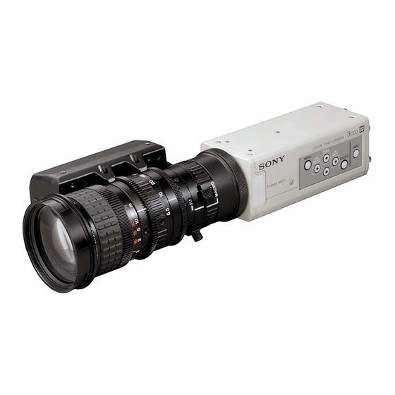
Sony DXC-390 Service Manual
3ccd color video camera
Hide thumbs
Also See for DXC-390:
- Instructions for use manual (260 pages) ,
- Service manual (110 pages) ,
- Manual (52 pages)
Table of Contents
Advertisement
Quick Links
Advertisement
Table of Contents

Related Manuals for Sony DXC-390


Summary of Contents for Sony DXC-390
- Page 1 3CCD COLOR VIDEO CAMERA DXC-390 DXC-390P SERVICE MANUAL 1st Edition...
- Page 2 ! WARNING This manual is intended for qualified service personnel only. To reduce the risk of electric shock, fire or injury, do not perform any servicing other than that contained in the operating instructions unless you are qualified to do so. Refer all servicing to qualified service personnel.
-
Page 3: Table Of Contents
Table of Contents Manual Structure Purpose of this manual ..................3 (E) Related manuals ....................3 (E) 1. Operating Instructions 2. Service Overview 2-1. Board location ..................2-1 (E) 2-2. Removal of cabinet ................2-1 (E) 2-3. Removal of CCD block ................. 2-2 (E) 2-4. - Page 4 5-3. Electrical Parts List ..................5-4 5-4. Packing Materials & Supplied Accessories ..........5-20 6. Semiconductor Pin Assignments index ......................6-1 IC ......................... 6-3 7. Block Diagrams DP-313 ......................7-1 EN-142 ......................7-2 MB-875 ....................... 7-3 SG-265 ......................7-4 VA-193 ......................7-5 8.
-
Page 5: Manual Structure
Manual Structure Purpose of this manual This manual is the Service Manual of the 3CCD color video camera DXC-390/390P. This manual contains the operating instructions, service overview, functions, electrical alignment, spare parts, semiconductor pin assignments, block diagrams, schematic diagrams and board layouts. Related manuals In addition to this Service Manual, the following manuals are provided for this unit. -
Page 7: Operating Instructions
Section 1 This section is extracted Operating Instructions from operation manual. 3-203-786-11(1) 3CCD Color Video Camera Instructions for Use (DXC-390P only) DXC-390 DXC-390P 2000 Sony Corporation 1-1 (E) DXC-390/390P... - Page 8 The model and serial numbers are located at the bottom. to operate this equipment. Record these numbers in the spaces provided below. Refer to these numbers whenever you call upon your Sony The shielded interface cable recommended in this manual dealer regarding this product.
- Page 9 Table of Contents Chapter 1 Chapter 3 Overview Installation and Connections Features ..............6 Installation .............. 42 Location and Functions of Parts and Controls ..8 Applicable Lens ........... 42 Mounting the Lens ..........43 Front Panel/Top Panel/Bottom Panel ..... 8 Mounting a Microscope Adaptor ......
-
Page 10: Overview
................................................... 1) Exwave HAD : Exwave Hole-Accumulated Diode 2) CCD: Charge-Coupled Device “Exwave HAD ” is a trademark of Sony Corporation. 3) “CCD IRIS ” is a trademark of Sony Corporation. (GB) Chapter 1 Overview equivalent of up to 10 aperture stops. When using the video... -
Page 11: Location And Functions Of Parts And Controls
Location and Functions of Parts and Controls 1 Lens Mount (C-mount) Front Panel/Top Panel/Bottom Panel Attach a C-mount lens or microscope adaptor. Note Be sure to use a lens whose projected part from the lens mount surface is less than 4.3 mm. Mounting the lens with a projected part greater than 4.3 mm may damage the internal mechanism of the camera. -
Page 12: Rear Panel
4 BARS (color bars output) button Outputs the color bar signal. Press again to revert to video signal output. For monitor adjustment, contact your authorized Sony dealer. 5 ENTER button Selects a setting menu in the MAIN menu. Also use this button for an AE window setting, etc. -
Page 13: Operation
Chapter Operation Adjusting and Setting with Menus Camera operational settings can be changed through simple About on-screen menus adjustment of the settings on the on-screen menus. Settings This section explains how to read the on-screen menu before can be adjusted to get the best possible results for the given starting menu operation. -
Page 14: Operation Through Menus
Adjusting and Setting with Menus Menu operation procedure Operation through Menus To change the settings on the menu, proceed as follows. Menu operation buttons Operate the menu with the buttons on the right side panel. button MENU BLACK MENU button button FILE SELECT... -
Page 15: Exposure Menu
Adjusting and Setting with Menus GAIN Function of Menus Adjusts the video gain. Selection Function EXPOSURE menu STEP Sets the video gain to the desired level. Use this Adjusts the items relating to exposure, such as gain and setting for shooting in an extremely dark place where even fully opening the lens iris still does not shutter mode. - Page 16 Adjusting and Setting with Menus Selection Function Selection Function Clear scan mode VARIABLE CCD-IRIS For example, this function is useful for microscope You can set the shutter speed in units of 1H applications. When shooting with a microscope not (Continued) (Continued) (horizontal scanning time: 63.56 µs for DXC-390, equipped with the auto-iris lens, the luminance level...
-
Page 17: Contrast Menu
Adjusting and Setting with Menus CONTRAST menu Selection Function 3 Move the cross cursor appearing at the right AE AREA Adjusts the contrast of the image. bottom corner with the button to set (Continued) the lower and right side size, then press the ENTER button. -
Page 18: White Balance Menu
Adjusting and Setting with Menus Adjusting Effect WHITE BALANCE menu direction Adjusts the white balance. The whole screen becomes whiter. The whole screen becomes blacker. – <WHITE BALANCE> >MODE R. (red) PEDESTAL, B. (blue) PEDESTAL R. PAINT B. PAINT Use these items to finely adjust the pedestal level of each color. - Page 19 Adjusting and Setting with Menus DETAIL ENHANCER menu Enables or disables adjustment of the sharpness of the image Adjusts the sharpness of the image outline and the color outline. tone (hue). Selection Function Enables adjustment of the sharpness of the image <ENHANCER>...
- Page 20 Adjusting and Setting with Menus CCD MODE GENERAL menu Selects the CCD read-out mode. Sets the general items. Selection Function Accumulates charges in field units. Use to shoot a FIELD moving object. <GENERAL> >CCD MODE FIELD Accumulates charges in frame units. Provides the SHADING COMP.
- Page 21 Adjusting and Setting with Menus D-SUB SYNC Setting item Contents of setting Ref. page Switches the sync signal output from the RGB/SYNC (VBS lock) Adjusts the horizontal phase and connector (D-sub 9-pin) at the rear panel. H. PHASE* SC (subcarrier) phase during SC.
-
Page 22: Initial Setting Of The Menus
Adjusting and Setting with Menus FILE SELECT SCENE FILE menu Selects the file A or B. Sets the preset menu settings. The camera has two memory files (A or B) for storing the LOAD menu settings. You can store a different type of setting into Sets the setting to be stored into the file which you select each file, and switch to the file most suitable for the with FILE SELECT, and stores the setting. -
Page 23: Shooting
Shooting The following is an example of flange focal length Adjusting the Flange Focal Length adjustment using the RM-C950 remote control unit. Adjust it using the FLANGE BACK (flange focal length) This section explains how to adjust the flange focal length adjustment ring on the camera. -
Page 24: Basic Shooting Procedure
Shooting When you use a zoom lens not equipped with Set the iris fully open if the lens is equipped with the the flange focal length adjustment function iris ring. If you use the auto iris lens, illuminate the object Adjust the flange focal length using the FLANGE BACK appropriately so that the iris is open. -
Page 25: Adjusting The Iris, Focus And Zoom
Shooting Adjusting the iris automatically Adjusting the Iris, Focus and Zoom Set the IRIS AUTO/MANUAL switch on the RM-C950 to AUTO. The following is an example of the iris, focus and zoom Note adjustments using the RM-C950 remote control unit. You cannot adjust the iris manually with the VCL- For details, refer to the Operating Instructions supplied with 610WEA. -
Page 26: Adjusting The Black Balance
Shooting Operation procedure Adjusting the Black Balance If any menu is displayed on the screen, press the MENU button to remove it. Be sure to adjust the black balance when you use the camera for the first time, or after you have not used it for a long If a color bar signal is displayed on the screen, press the period of time, or if there is a sudden change in the BARS button to remove it. -
Page 27: Adjusting The Picture Tone In A Multi-Camera System
Shooting Press the WHITE button. Place a white object (white pattern, white cloth, etc.) in During adjustment the bars appear. The message the same light as that falling on the object to be shot, “WHITE: OK” appears on the screen when the then zoom in on the white object to fill the screen as adjustment is done. -
Page 28: Installation And Connections
Chapter Installation and Connections Installation Note Applicable Lens Be sure to use a lens whose projected part from the lens mount surface is less than 4.3 mm. Mounting the lens with a C-mount lenses with the following lens mount surface can projected part greater than 4.3 mm may damage the internal be attached to the camera. -
Page 29: Mounting A Microscope Adaptor
Installation Remove the mount caps of the camera and lens. Mounting the VCL-614WEA Zoom Lens Align the threaded portion of the lens mount with that of the camera mount, and turn the mount lock ring clockwise as far as it goes to fix the lens to the camera. Lens control cable Connect the lens control cable to the LENS connector on the camera. -
Page 30: Basic System Connection
Installation Reference dimensions for attaching a tripod Bottom 40 (1 5 Hole (depth: 5 ( 14 ( 45.5 (1 5 Hole (depth: 5 ( 14 ( Tripod screw (depth: 7 ( Unit: mm (inches) 23.5 Tripod screw (depth: 7 ( Side Tripod adaptor Tripod adaptor... -
Page 31: Connecting To Video Equipment With Composite Video Input Connectors
Basic System Connection Connecting to Video Equipment with Composite Video Input Connectors Connecting using the CCDC cable Composite video input (VIDEO IN) 75-ohm coaxial cable Video monitor, DXC-390/390P VCR, etc. VIDEO OUT VIDEO OUT Set the MODE DC IN/VBS selector to the “1” position. -
Page 32: Connecting To Video Equipment With Rgb Or S-Video Inputs
Basic System Connection Connecting to Video Equipment with RGB or S-Video Inputs Set the MODE selector CMA-D2/D2MD/D2CE/ to the “1” position. D2MDCE camera adaptor CCDC-5/10/25/50A/100A cable or Power cord CCMC-12P02/05/10/25 cable* CAMERA (4-pin or 12-pin) RGB monitor, Camera cable: CCXC-9DB (D-sub 9-pin DC IN/VBS image processor, R input... -
Page 33: Connecting To A Remote Control Unit
Connecting to a Remote Control Unit You can connect the RM-C950 remote control unit. 75-ohm coaxial cable Video monitor, VCR, etc. Composite video input VIDEO OUT RM-C950 remote control unit DXC-390/390P VIDEO OUT DC IN/VBS Set the MODE CMA-D2/D2MD/ TRIG IN LENS selector to the “1”... -
Page 34: Connecting To A Computer
System for controlling the camera with a computer using an RS-232C command For more details on RS-232C protocols and cables for connection to a 1) Use the shielded connecting cable for connecting to a computer. computer, contact your authorized Sony dealer. (GB) Chapter 3 Installation and Connections... -
Page 35: Connections For Shooting Using A Flash
Connections for Shooting Using a Flash Flash Power cord CMA-D2/D2MD/D2CE/ D2MDCE camera adaptor Synchronization cable Set the MODE Slave unit selector to the “1” position. DXC-390/ Video input 390P DC IN/ connector VIDEO OUT DC IN/VBS TRIG IN LENS MENU LOCK TRIG IN RGB/SYNC REMOTE... - Page 36 LEVEL LOW • Increase the illumination. adjustment, the camera needs to be checked. • Widen the iris opening. Consult your authorized Sony dealer. • Increase the video gain. Take the measures above, then press the WHITE button. WHITE: NG The video level of the image is too high.
- Page 37 Specifications Image system/optical system Functions/performance Image device Horizontal resolution 1/3 type CCD, interline transfer type 800 TV lines Effective picture elements Sensitivity 2000 lux (F8, 3,200K) DXC-390: 768 (horizontal) 494 (vertical) Signal-to-noise ratio DXC-390P: 752 (horizontal) 582 (vertical) DXC-390: 62 dB Lens mount C-mount DXC-390P: 61 dB Gain control AGC: Automatic Gain Control...
- Page 38 Specifications Medical specifications Demensions Protection against electric shock Front Class I Protection against harmful ingress of water 56 (2 Ordinary Degree of safety in the presence of flammable anesthetics or oxygen Not suitable for use in the presence of flammable anesthetics or oxygen Mode of operation Continuous Design and specifications are subject to change without...
- Page 39 Optional Accessories Lenses Power supply cable VCL-614WEA zoom lens (14 , f = 5.5 – 77 mm) CCDC series (length: 5 m [16 ft], 10 m [32 ft], or 25 m VCL-610WEA zoom lens (10 , f = 6.5 – 65 mm) [82 ft]) CCDCA series (length: 50 m [164 ft], or 100 m [328 ft]) CCMC series (length: 2 m [7 ft], 5 m [16 ft], 10 m [32 ft], or...
-
Page 41: Service Overview
Section 2 Service Overviw 2-1. Board location 2-2. Removal of cabinet 1. Remove the seven screws (P2 x 3) and then remove EN-142/142P SG-265/265P board the upper case. board 2. Remove the two screws (P2 x 3) and then remove the DP-313/313P board stay. -
Page 42: Removal Of Ccd Block
2-3. Removal of CCD block 2-4. How to use an extension board 1. Remove the upper case and stay, referring to the Extension boards are not in use for adjustment. These are in use for check of VA-193/193P, DP-313/313P, Section 2-2. “ Removal of cabinet ”. EN-142/142P, SG-265/265P boards. - Page 43 ..In cases of the EN-142/142P board EN-142/142P board Extension board EX-747 Extension board EX-748 ..In cases of the SG-265/265P board SG-265/265P board Extension board EX-749 Extension board EX-750 2-3 (E) DXC-390/390P...
-
Page 44: Input/Output Signals Of Connectors
2-5. Input/output signals of connectors REMOTE VIDEO OUT DC IN/VBS TRIG IN LENS (External view) MENU LOCK REMOTE connector (8-pin) RGB/SYNC REMOTE Pin No. Signal HSK output HSK input DXC-390/390P REAR PANEL TXD__ RXD__ LENS TXD_+ UNREG_+ RXD_+ RGB/SYNC (External view) (External view) RGB/SYNC connector (D-sub 9-pin) LENS connector (6-pin) -
Page 45: Circuit Operation Description
Section 3 Circuit Operation Description 3-1. VA-193 Board (3) Shading Compensation Circuit V-periodic delta wave is generated, it uses the voltage for VCA gain control, so that shading compensation The VA-193 board consists of the circuit blocks described function is realized. below. -
Page 46: Board
3-3. EN-142 Board (1) A/D converter circuit for video signal The analog signal (RGB) that is processed every kind The EN-142 board generates the composite signal (VBS at the VA-193 board, is converted to 10-bit digital and Y/C) by the encoder IC from Y, CR (R-Y) and CB (B- signal at CXD2310AR (from IC401 to IC403). -
Page 47: Board
3-4. SG-265 Board ..External sync signal (VBS and HD/VD) Sync mode is discriminated by a input sync source signal from external. SYNC and BURST are separated from its The microprocessor communicates a data with each board, signal and input to IC230, compare phase with the and controls a camera. -
Page 48: Board
3-5. MB-875 Board The MB-875 board is installed the oscillator circuit for master clock, the timing generator for the CCD driving pulse, the IC generated detection boundary and the DC-DC converter..28 MHz oscillating circuit This circuit consists of the P-COMP (HD phase compar- ative output) signal and PLL in VCO. -
Page 49: Electrical Alignment
. For video level adjustment, etc. Termination (75Z) Vectorscope Color monitor Commercially Available Products . Vectorscope . Waveform monitor . Frequency counter . Signal generator . Digital voltmeter . Color monitor . Lens (C-mount type and manual iris type) Termination (75Z) 4-1 (E) DXC390/390P... -
Page 50: Description Of Side Panel Sheet Switches
4-2. Adjustment 4-2-1. VCO Adjustment 4-1-3. Description of Side Panel Sheet (original oscillator adjustment) Switches Equipment : Monitor screen Adj. no. is selected by the arrow t (up) or the arrow Preparation : Input the VBS OUT on a camera to T(down). -
Page 51: Ccd Out Adjustment
16. Make settings the Adj98 data to 004. 17. Make settings the Adj99 data to 002. 18. Make settings the Adj100 data to 024. 19. Turn the S102 switch on the SG-265 board to the OPE side (up side). DXC-390P 4-3 (E) DXC390/390P... -
Page 53: Spare Parts
Therefore, specified parts should be used in the case of replacement. 2. Standardization of Parts Some repair parts supplied by Sony differ from those used for the unit. These are because of parts common- ality and improvement. Parts list has the present standardized repair parts. -
Page 54: Exploded View
5-2. Exploded View DXC-390/390P... - Page 55 NO. Part No. SP Description A-8325-284-A o PANEL ASSY,REAR A-8325-287-A o MOUNTED CIRCUIT BOARD,PA-236 A-8325-288-A o MOUNTED CIRCUIT BOARD,VA-193 A-8325-289-A o MOUNTED CIRCUIT BOARD,DP-313[for UC,J] A-8325-309-A o MOUNTED CIRCUIT BOARD,DP-313P[for CE] A-8325-290-A o MOUNTED CIRCUIT BOARD,EN-142[for UC,J] A-8325-310-A o MOUNTED CIRCUIT BOARD,EN-142P[for CE] A-8325-292-A o MOUNTED CIRCUIT BOARD,MB-875[for UC,J] A-8325-312-A o MOUNTED CIRCUIT BOARD,MB-875P[for CE] A-8325-293-A o MOUNTED CIRCUIT BOARD,CN-1938...
-
Page 56: Electrical Parts List
5-3. Electrical Parts List ------------- CN-1938 BOARD (CN-1938 BOARD) ------------- Ref. No. Ref. No. or Q'ty Part No. SP Description or Q'ty Part No. SP Description A-8325-293-A o MOUNTED CIRCUIT BOARD, CN-1938 L014 1-410-981-31 s CHIP INDUCTOR 0.1UH (2012) L015 1-410-981-31 s CHIP INDUCTOR 0.1UH (2012) C001 1-164-858-11 s CAPACITOR,CERAMIC 22PF/16V 1005... - Page 57 ------------ DP-313 BOARD (DP-313 BOARD) ------------ Ref. No. Ref. No. or Q'ty Part No. SP Description or Q'ty Part No. SP Description A-8325-289-A o MOUNTED CIRCUIT BOARD, DP-313 C474 1-107-820-11 s CAPACITOR,CHIP CERAMIC 0.1MF F [for UC,J] C475 1-107-820-11 s CAPACITOR,CHIP CERAMIC 0.1MF F A-8325-309-A o MOUNTED CIRCUIT BOARD, DP-313P C476 1-104-851-11 s CAPACITOR,TANTALUM 10MF/10V...
- Page 58 (DP-313 BOARD) (DP-313 BOARD) Ref. No. Ref. No. or Q'ty Part No. SP Description or Q'ty Part No. SP Description R444 1-218-965-11 s RESISTOR,CHIP 10K 1/16W [for UC,J] R555 1-218-990-11 s RESISTOR,CHIP 0 1/16W (1005) R446 1-218-965-11 s RESISTOR,CHIP 10K 1/16W R556 1-218-953-11 s RESISTOR,CHIP 1K 1/16W R458...
- Page 59 ------------ EN-142 BOARD (EN-142 BOARD) ------------ Ref. No. Ref. No. or Q'ty Part No. SP Description or Q'ty Part No. SP Description A-8325-290-A o MOUNTED CIRCUIT BOARD, EN-142 C757 1-107-820-11 s CAPACITOR,CHIP CERAMIC 0.1MF F [for UC,J] C758 1-107-820-11 s CAPACITOR,CHIP CERAMIC 0.1MF F A-8325-310-A o MOUNTED CIRCUIT BOARD, EN-142P C759 1-164-874-11 s CAPACITOR,CHIP CERAMIC 100PF...
- Page 60 (EN-142 BOARD) (EN-142 BOARD) Ref. No. Ref. No. or Q'ty Part No. SP Description or Q'ty Part No. SP Description 8-759-523-02 s IC TC74HC4053AFT(EL) Q739 8-729-117-32 s TRANSISTOR 2SC4177 IC701 8-759-064-36 s IC MB88346BPFV IC702 8-759-058-62 s IC TC7S08FU-TE85R R701 1-218-990-11 s RESISTOR,CHIP 0 1/16W (1005) IC703 8-759-196-69 s IC BA7655AF-E2...
- Page 61 (EN-142 BOARD) (EN-142 BOARD) Ref. No. Ref. No. or Q'ty Part No. SP Description or Q'ty Part No. SP Description R757 1-208-688-11 s RESISTOR,CHIP 1.6K 1/16W 1005 R815 1-208-675-11 s RESISTOR,CHIP 470 1/16W (1005) R758 1-208-663-11 s RESISTOR,CHIP 150 1/16W (1005) R816 1-208-679-11 s RESISTOR,CHIP 680 1/16W (1005) R759...
- Page 62 ------------ MB-875 BOARD (MB-875 BOARD) ------------ Ref. No. Ref. No. or Q'ty Part No. SP Description or Q'ty Part No. SP Description A-8325-292-A o MOUNTED CIRCUIT BOARD, MB-875 C660 1-113-682-11 s CAPACITOR,TANTALUM 33MF/10V [for UC,J] C661 1-115-705-11 s CAPACITOR,ELECT 150MF / 6.3V A-8325-312-A o MOUNTED CIRCUIT BOARD, MB-875P C662 1-113-682-11 s CAPACITOR,TANTALUM 33MF/10V...
- Page 63 (MB-875 BOARD) (MB-875 BOARD) Ref. No. Ref. No. or Q'ty Part No. SP Description or Q'ty Part No. SP Description IC614 8-759-257-96 s IC TC7S14FU(TE85R) R630 1-218-965-11 s RESISTOR,CHIP 10K 1/16W IC615 8-759-195-81 s IC TC7S86FU R632 1-218-953-11 s RESISTOR,CHIP 1K 1/16W IC616 8-759-058-62 s IC TC7S08FU-TE85R R633...
- Page 64 ------------ (MB-875 BOARD) PA-236 BOARD ------------ Ref. No. Ref. No. or Q'ty Part No. SP Description or Q'ty Part No. SP Description TP601 1-535-757-11 s CHIP, CHECKER (CONNECTOR) A-8325-287-A o MOUNTED CIRCUIT BOARD, PA-236 X601 1-767-618-11 s OSCILLATOR, CRYSTAL [for UC,J] C101 1-107-826-11 s CAPACITOR,CHIP CERAMIC 0.1MF X601...
- Page 65 ------------ SG-265 BOARD (SG-265 BOARD) ------------ Ref. No. Ref. No. or Q'ty Part No. SP Description or Q'ty Part No. SP Description A-8325-909-A o MOUNTED CIRCUIT BOARD, SG-265 C234 1-164-943-11 s CAPACITOR,CHIP CERAMIC 0.01MF [for UC,J] C235 1-113-642-11 s CAPACITOR,TANTALUM 47MF/10V A-8325-910-A o MOUNTED CIRCUIT BOARD, SG-265P C236 1-107-820-11 s CAPACITOR,CHIP CERAMIC 0.1MF F...
- Page 66 (SG-265 BOARD) (SG-265 BOARD) Ref. No. Ref. No. or Q'ty Part No. SP Description or Q'ty Part No. SP Description C290 1-104-913-11 s CAPACITOR,CHIP TANTALUM 10MF/16V IC238 8-759-101-12 s IC UPC311G2 C291 1-113-981-11 s CAPACITOR,TANTALUM 22MF/20V IC239 8-759-195-81 s IC TC7S86FU C292 1-104-851-11 s CAPACITOR,TANTALUM 10MF/10V IC240...
- Page 67 (SG-265 BOARD) (SG-265 BOARD) Ref. No. Ref. No. or Q'ty Part No. SP Description or Q'ty Part No. SP Description R119 1-218-965-11 s RESISTOR,CHIP 10K 1/16W R183 1-218-953-11 s RESISTOR,CHIP 1K 1/16W R120 1-218-965-11 s RESISTOR,CHIP 10K 1/16W R184 1-208-707-11 s RESISTOR,CHIP 10K 1/16W (1005) R121 1-218-965-11 s RESISTOR,CHIP 10K 1/16W R185...
- Page 68 (SG-265 BOARD) (SG-265 BOARD) Ref. No. Ref. No. or Q'ty Part No. SP Description or Q'ty Part No. SP Description R282 1-208-703-11 s RESISTOR,CHIP 6.8K 1/16W(1005) R341 1-218-969-11 s RESISTOR,CHIP 22K 1/16W (1608) R283 1-218-957-11 s RESISTOR,CHIP 2.2K 1/16W(1608) R342 1-208-899-11 s RESISTOR,CHIP 3.3K 1/16W(1005) R284 1-218-953-11 s RESISTOR,CHIP 1K 1/16W...
- Page 69 ------------ VA-193 BOARD (VA-193 BOARD) ------------ Ref. No. Ref. No. or Q'ty Part No. SP Description or Q'ty Part No. SP Description A-8325-288-A o MOUNTED CIRCUIT BOARD, VA-193 C962 1-113-985-11 s CAPACITOR,TANTALUM 10MF/20V C963 1-113-985-11 s CAPACITOR,TANTALUM 10MF/20V C901 1-107-820-11 s CAPACITOR,CHIP CERAMIC 0.1MF F C964 1-113-985-11 s CAPACITOR,TANTALUM 10MF/20V C902...
- Page 70 (VA-193 BOARD) (VA-193 BOARD) Ref. No. Ref. No. or Q'ty Part No. SP Description or Q'ty Part No. SP Description C1026 1-104-852-11 s CAPACITOR,TANTALUM 22MF/10V Q915 8-729-402-84 s TRANSISTOR XN4601 C1027 1-104-851-11 s CAPACITOR,TANTALUM 10MF/10V Q916 8-729-402-84 s TRANSISTOR XN4601 C1028 1-104-851-11 s CAPACITOR,TANTALUM 10MF/10V Q917...
- Page 71 (VA-193 BOARD) (VA-193 BOARD) Ref. No. Ref. No. or Q'ty Part No. SP Description or Q'ty Part No. SP Description R947 1-218-957-11 s RESISTOR,CHIP 2.2K 1/16W(1608) R1006 1-208-713-11 s RESISTOR,CHIP 18K 1/16W (1005) R948 1-218-972-11 s RESISTOR,CHIP 39K 1/16W (1005) R1007 1-220-196-11 s RESISTOR,CHIP 13K 1/16W (1005) R949...
-
Page 72: Packing Materials & Supplied Accessories
5-4. Packing Materials & Supplied (VA-193 BOARD) Accessories Ref. No. Ref. No. or Q'ty Part No. SP Description or Q'ty Part No. SP Description TP906 1-535-757-11 s CHIP, CHECKER (CONNECTOR) 3-203-786-01 s MANUAL, INSTRUCTION [for J] TP907 1-535-757-11 s CHIP, CHECKER (CONNECTOR) 3-203-786-11 s MANUAL, INSTRUCTION [for UC,CE] TP908 1-535-757-11 s CHIP, CHECKER (CONNECTOR) -
Page 73: Index
In addition, for semiconductors with ID Nos., refer to the separate CD-ROM titled “Semiconductor Pin Assignments” (Sony Part No. 9-968-546-xx) that allows searching for parts by semiconductor type or ID No. The semiconductors in the manual or on the CD-ROM are listed by equivalent types. - Page 74 Index Page or ID No. Page or ID No. AT28BV64-30TC ........... AT28C64B-15TC TC7SET08FU(TE85R) ............TC7S08F TC7SH04FU ..............TC7S04F BA10358F-E2 ..............RC4558 TC7SH04FU-TE85R ............TC7S04F BA7655AF-E2 ..............BA7655AF TC7SH08FU-TE85R ............TC7S08F TC7SH32FU-TE85R ............TC7S32F CXA1592R ..............CXA1392R TC7W08FU ..............TC7W08F CXA1592R-TH ............... CXA1392R TC7W08FU(TE12R) ............
- Page 75 [|IC|] CXA1757R-T6 (SONY) INPUTS HEAD AMP FOR MULTI CCD DIGITAL CAMERA AGCCONT : AGC GAIN CONTROL —TOP VIEW— AGCMAX : MAX AGC GAIN CONTROL BDIN : B CHANNEL CCD SIGNAL BGAIN : B GAIN CONTROL BPIN : B CHANNEL CCD SIGNAL...
- Page 76 CXD1256AR (SONY) INPUTS TIMING GENERATOR FOR CCD CAMERA : NTSC (1820 fH)/PAL (1816 fH) CLOCK —TOP VIEW— : NORMALLY FIX TO “LOW” LEVEL COLOR /BW SELECT FIELD /FRAME SELECT NTSC (EIA) /PAL (CCIR) SELECT ED0 - ED2 : SHUTTER SPEED SETTING...
- Page 77 ICX258AL (SONY) LT1251CS (LINEAR TECH) ICX259AL (SONY) VIDEO FADER AND DC GAIN CONTROL AMPLIFIER —TOP VIEW— 1/3-INCH CCD IMAGE BLOCK —TOP VIEW— CONTROL NULL INPUTS H1, H2 : HORIZONTAL REGISTER TRANSFER CLOCK : RESET GATE CLOCK : OVERFLOW DRAIN : PROTECTION TRANSISTOR BIAS...
-
Page 79: Block Diagrams
DP-313 DP-313 Section 7 Block Diagrams CN401 CN401 NIC-BUSY OBLK NIC-CS CS-DSP SDI-3 SDCK SDO-3 SDA3 SCLK-3 SDA2 SDA1 SDA0 IC401 CN401 VIDEO G(10bit) CONV CN401 AVD_5 IC402 CN401 CXD9117R CXD9087R VIDEO R(10bit) IC404 IC409 VIDEO CN401 CONV B(10bit) CONV. IC410 IC403 CN701... - Page 80 EN-142 EN-142 CN701 CN701 IC704 LALT INTSC IC844 S701 (2/2) OBLK IC849 CN701 CLP4 (1/2) TTLB IC708 CXA1592R CN701 FL701 Q701,704 DL701 CN701 Driver BUFF FL703 Q703,706 CN701 CN701 BUFF Driver VBS/Y ENCODER IC703 FL702 Q702,705 CN701 CN701 BUFF _ /C Driver CN701 B-Y GAIN...
- Page 81 MB-875 MB-875 IC629(1/2) W2_DISP CN604 CN602 WDISPLAY CP_DISP SDATA-5 SCLK-5 IC628(1/2) KIS-CS W2_BLK CN604 IC606 KIS-STB W2_OE WDISPLAYB CP_BLK EVR06-CS IC602 CP_OE CN603 IC619(1/3,2/3) WIN_OE W0_H CN604 WEPH DTAR W0_V CN606 CONV CDTAR FILTER UNREG(LENS) WECHANGE W1_H CXD9115AR CN606 WEPOL W1_V 24,25,26 UNREG(+)
- Page 82 SG-265 SG-265 IC243(1/3) CN103 P-COMT CN103 VCO_CONT N:1k P:NM IC243(2/3) N: NTSC (DXC-390) IC231 N:NM IC230 HCOMOUT HCOMOUT P: PAL (DXC-390P) P:1k SYNC IN NM: NO MOUNT INT/EXT IC246 INT_HD 4FSCOUT (3/3) CN103 LALTR LALTR 4 FSC CLOUT CXD1216M CXD1217Q N:NM SC PHASE P:1k...
- Page 83 VA-193 VA-193 IC 909(1/2) CN901 IC905(4/4) CLPOPB CN901 ZOOM ZOOM IC 920(1/2) CN901 PBLK CLPBL IRIS OPEN CN901 FOCUS FOCUS CLPDM R CDS OUT Q914(1/3),IC907(2/3) X SHP IC908 IC905(3/4) X SHD G CDS OUT YMTX CLAMP IC913 CN901 B CDS OUT IRIS Y GAIN CONT IC905(1/4)
-
Page 85: Schematic Diagrams
Section 8 Schematic Diagrams DXC-390/390P... - Page 86 Frame Frame CN102 CN902 PA(R) R PA -7.5V -7.5V PA-236 VA-193 +15V +15V PA(G) G PA PA(B) B PA CN101 CN601 V1(B) V1(B) V2(B) V2(B) V3(B) V3(B) V4(B) V4(B) H2(B) H2(B) H1(B) H1(B) RG(B) RG(B) VSUB(B) VSUB(B) V1(G) V1(G) V2(G) V2(G) MB-875 V3(G)
-
Page 87: Frame
Frame Frame DP-313 CN-1938 CN002 UNREG_G DC IN UNREG_+ /VBS VBS/Y_G VBS/Y_X FLAT CABLE 30P -/HD_G CN606 CN007 -/HD_X FOCUS_CONT FOCUS CONT SYNC/VD_X ZOOM_CONT ZOOM CONT -/C_G IRIS_CLOSE IRIS CLOSE -/C_X IRIS_CONT/VIDEO IRIS CONT/VIDEO UNREG_G HSK_O HSK_O UNREG_+ HSK_I HSK_I SYNC/VD_G TX_DATA TXDATA... -
Page 88: Cn-1938
CN-1938 CN-1938 CN007 (30/30) UNREG(G) CN007 (29/30) UNREG(G) CN007 (28/30) UNREG(G) D001 CN007 (26/30) UNREG(+) D2FL20U-TA F001 CN007 (25/30) UNREG(+) 1.6A CN007 (24/30) UNREG(+) L007 0.1uH CN007 (22/30) HD IN/HD OUT L008 0.1uH CN007 (21/30) VD IN/VD OUT C008 C009 C012 22pF 22pF... -
Page 89: Pa-236
PA-236 PA-236 Q101 # IC101 2SC4177-T1L5L6 ICX258AL-1 (N) ICX259AL-1 (P) C101 R102 0.1uF VOUT C102 C104 0.1uF 47uF C105 0.01uF CSUB C106 C107 R103 C108 (FLEXIBLE) 0.1uF 10uF CN101 5.6k 0.01uF GND1 GND2 (FLEXIBLE) CN102 V1(B) PA(B) V2(B) C103 V3(B) PA(G) V4(B) R101... - Page 90 DP-313 DP-313 CN401 (2/70) +5V(D) CN401 (4/70) +5V(D) CN401 (62/70) +5V(D) IC422 (1/2) CN401 (50/70) OBLK IC422 (2/2) R445 R457 R459 C483 CN401 (1/70) +3.3V CN401 (3/70) +3.3V R446 R458 R460 R464 R567 CN401 (5/70) +3.3V R581 # R443 # R444 R568 CN401 (51/70)
- Page 91 DP-313 DP-313 +5V(A) (6/70) CN401 (57/70) CN401 +5V(A) R573 (17/70) CN401 WRGBCH0 WRGBCH0 CN401 WRGBCH1 WRGBCH1 (19/70) (24/70) CN401 BECOL BECOL R574 (22/70) CN401 R507 R508 WB_AE WB_AE (13/70) CN401 R572 R493 R511 R512 R513 R591 R592 R571 R522 R524 CL409 R575 C457...
-
Page 92: En-142
EN-142 EN-142 CN701 (50/50) CN701 (49/50) L701 22uH CN701 (48/50) CN701 (47/50) Q711 IC844 (2/2) IC849 (2/2) Q701 Q704 Q707 Q708 Q709 2SC4177-T1L5L6 2SA1611-T1M6 2SA1611-T1M6 2SC4177-T1L5L6 2SC4103T106-Q 2SC4177-T1L5L6 TC7SET08FU(TE85R) TC7SET08FU(TE85R) CN701 (1/50) +5V(A) CN701 (2/50) L702 +5V(A) 22uH CN701 (3/50) +5V(A) CN701 (4/50) - Page 93 EN-142 EN-142 L705 22uH L704 Q731 Q736 22uH 2SC4177-T1L5L6 2SC4177-T1L5L6 IC708 LT1361CS8-E2 CN701 (38/50) VBS/Y R787 R788 R789 R791 R815 R828 3.3k 3.3k 3.3k 3.3k R839 (1/3) RN-C RN-C TC74HC4053AFT(EL) (1608) +INA OUTA RN-C CN701 (37/50) C777 R819 33uF R829 -INA 6.3V RN-C...
-
Page 94: Sg-265 (1/2)
SG-265 (1/2) SG-265 (1/2) ope/48J IRIS-CLOSE IC115 R135 R105 TA75S558F(TE85R) R131 R134 R183 R141 R143 CN103 (46/70) CLOSE C115 R184 0.1uF RN-C 3 IN- R185 ADBIAS1 C149 6.8k IC101 0.1uF R136 RN-C S101 S102 C146 C147 C148 X24645S8I-2.7T2 R138 TP106 0.1uF 0.1uF C114... - Page 95 SG-265 (1/2) SG-265 (1/2) PROTECT (43/70) CN103 L102 CN103 NIC_BUSY (21/70) 22uH CN103 NIC_CS (22/70) (23/70) CN103 SDO-3 C142 CN103 22uF SCLK-3 (24/70) CN103 SDI-3 (25/70) CN103 SDA0 (26/70) CN103 SDA1 (27/70) (28/70) CN103 SDA2 CN103 SDA3 (29/70) CN103 SDCK (30/70) (31/70) CN103...
-
Page 96: Sg-265 (2/2)
SG-265 (2/2) SG-265 (2/2) IC243 (1/3) TC74HC4053AFT(EL) CN103 (60/70) P-COMP IC231 CXD1217Q-T4 IC230 CXD1216M-TH C235 C236 C231 C232 47uF 0.1uF 47uF 0.1uF # R242 R237 # R240 R347 10 HCOMIN 8 4FSCIN # R235 HCOMOUT 4FSCOUT TEST 15 HDIN CLIN CLOUT 18 ISCIN MODE1... - Page 97 SG-265 (2/2) SG-265 (2/2) IC244 (3/3) IC240 IC244 (2/3) IC245 (2/2) TC74HC4538AFT(EL) TC74HC4538AFT(EL) TC7S08FU(TE85R) TL062CPWR C254 R269 560pF 3.3k (1608) RN-C R270 R274 C264 R267 2.4k 0.1uF RN-C T2 10 RN-C C250 R271 0.1uF 100k R284 C260 4FSC (44/70) CN103 0.022uF R273 R275...
-
Page 98: Va-193 (1/2)
VA-193 (1/2) VA-193 (1/2) TP911 TP912 C905 C907 C909 R901 0 CN901 (16/50) C906 C908 C910 IC921 (1/2) X SHD IC920 (2/2) R902 0 R1054 CN901 (15/50) X SHP TC7S08FU(TE85R) R903 CN901 (23/50) CLPDM R1052 R1010 C1026 IC910 3.3k Q922 22uF LT1251CS-E2 2SC4177-T1L5L6... -
Page 99: Va-193 (2/2)
VA-193 (2/2) VA-193 (2/2) TP901 IRIS (33/50) CN901 Q902 IC905 IC905 (1/4) IC908 IC913 IC905 IC905 (4/4) (2/4) (3/4) 2SC4177-T1L5L6 TL064CPW-E05 TC4W53FU(TE12R) TC4W53FU(TE12R) TL064CPW-E05 TL064CPW-E05 TL064CPW-E05 CN901 (11/50) -7.5V Q914 IC907 (1/3) IC907 (2/3) R1006 Q901 Q903 Q905 Q904 Q909 CN901 (13/50) -7.5V... -
Page 100: Mb-875 (1/3)
MB-875 (1/3) MB-875 (1/3) R661 L606 (1608) UNREG(LENS) R662 C680 (1608) 0.0022uF C665 R663 (1608) 82uF (1608) R664 L607 (1608) 4.7uH UNREG(+) C673 C676 C678 C679 DD601 0.01uF 15uF 15uF 0.01uF (1608) (1608) L601 UNREG(G) +15V UNREG1 22uH UNREG2 1/3, 3/3 +15V L608 4.7uH... -
Page 101: Mb-875 (2/3)
MB-875 (2/3) MB-875 (2/3) IC621 (1/2) IC621 (2/2) TC7WH74FU(TE12R) TC7WH74FU(TE12R) R607 R608 XSHP CLPOB CLPOB XSHD XSHP XSHP XSHD XSHD CLPDM CLPDM PBLK PBLK R642 FLD/FRAM Q603 R668 L615 IC635 (2/2) 2SA1611-T1M6 22uH TC7SH04FU-TE85R HDDET IC636 (2/2) Q602 IC603 R669 IC625 (3/3) CLPBL... -
Page 102: Mb-875 (3/3)
MB-875 (3/3) MB-875 (3/3) SG-265 EN-142 DP-313 VA-193 CN602 CN604 CN603 CN605 +5V(A) GND(D) GND(A) CN601 GND(A) +5V(A) GND(A) +5V(A) PA-236 GND(D) GND(A) GND(A) +5V(A) GND(A) CLP4 GND(A) TRIGGER GND(A) GND(A) HDDET OBLK GND(A) VCO_CONT GND(A) RESET5 +5V(D) LALT SYNC GND(A) P-COMP CLPDSP... - Page 103 CN-1938, PA-236 CN-1938, PA-236 Section 9 Board Layouts CN-1938 CN-1938 -A side- -B side- PA-236 PA-236 SUFFIX: -11 SUFFIX: -11 -A side- -B side- SUFFIX: -11 SUFFIX: -11 CN-1938 CN-1938 -A side- -B side- SUFFIX: -11 SUFFIX: -11 PA-236 PA-236 -A side- -B side- SUFFIX: -11...
- Page 104 DP-313 DP-313 DP-313 DP-313 -A SIDE- -B SIDE- SUFFIX: -11 SUFFIX: -11 DP-313 DP-313 -A SIDE- -B SIDE- SUFFIX: -11 SUFFIX: -11 DXC-390/390P...
- Page 105 EN-142 EN-142 EN-142 EN-142 -A SIDE- -B SIDE- SUFFIX: -11 SUFFIX: -11 EN-142 EN-142 -A SIDE- -B SIDE- SUFFIX: -11 SUFFIX: -11 DXC-390/390P...
- Page 106 MB-875 MB-875 MB-875 MB-875 -A SIDE- -B SIDE- SUFFIX: -11 SUFFIX: -11 MB-875 MB-875 -A SIDE- -B SIDE- SUFFIX: -11 SUFFIX: -11 DXC-390/390P...
- Page 107 SG-265 SG-265 SG-265 SG-265 -A SIDE- -B SIDE- SUFFIX: -11 SUFFIX: -11 SG-265 SG-265 -A SIDE- -B SIDE- SUFFIX: -11 SUFFIX: -11 DXC-390/390P...
- Page 108 VA-193 VA-193 VA-193 VA-193 -A SIDE- -B SIDE- SUFFIX: -11 SUFFIX: -11 VA-193 VA-193 -A SIDE- -B SIDE- SUFFIX: -11 SUFFIX: -11 DXC-390/390P...
- Page 110 DXC-390 (J, UC) Printed in Japan Sony Corporation DXC-390P (CE) J, E 2000. 4 26 Communication System Solutions Network Company 9-955-208-01 ©2000...