Desa GN30T Safety Information And Installation Manual
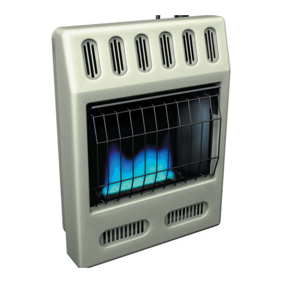
Unvented (vent-free) blue flame gas heater
Hide thumbs
Also See for GN30T:
- Safety information and installation manual (32 pages) ,
- Safety information and installation manual (28 pages)
Table of Contents
Advertisement
UNVENTED (VENT-FREE) BLUE FLAME GAS HEATER
SAFETY INFORMATION AND INSTALLATION MANUAL
GN30, GP30, GN30T, GP30T, GWN20, GWP20,
GWN20T, GWP20T, GWN30T, GWP30T, WMN20, WMP20
WARNING: If the information in this manual is not followed
exactly, a fire or explosion may result causing property
damage, personal injury, or loss of life.
— Do not store or use gasoline or other flammable vapors and
liquids in the vicinity of this or any other appliance.
— WHAT TO DO IF YOU SMELL GAS
• Do not try to light any appliance.
• Do not touch any electrical switch; do not use any phone in
your building.
• Immediately call your gas supplier from a neighbor's phone.
Follow the gas supplier's instructions.
• If you cannot reach your gas supplier, call the fire department.
— Installation and service must be performed by a qualified
installer, service agency, or the gas supplier.
For more information, visit www.desatech.com
Save this manual for future reference.
Advertisement
Table of Contents

Related Manuals for Desa GN30T


Summary of Contents for Desa GN30T
- Page 1 UNVENTED (VENT-FREE) BLUE FLAME GAS HEATER SAFETY INFORMATION AND INSTALLATION MANUAL GN30, GP30, GN30T, GP30T, GWN20, GWP20, GWN20T, GWP20T, GWN30T, GWP30T, WMN20, WMP20 WARNING: If the information in this manual is not followed exactly, a fire or explosion may result causing property damage, personal injury, or loss of life.
-
Page 2: Table Of Contents
WARNING: Improper installation, adjustment, altera- tion, service, or maintenance can cause injury or prop- erty damage. Refer to this manual for correct installation and operational procedures. For assistance or addi- tional information consult a qualified installer, service agency, or the gas supplier. WARNING: This is an unvented gas-fired heater. -
Page 3: Safety Information
SAFETY INFORMATION IMPORTANT: Read this owner’s manual carefully and completely before trying to assemble, oper- ate, or service this heater. Im- proper use of this heater can cause serious injury or death from burns, fire, explosion, elec- trical shock, and carbon mon- oxide poisoning. -
Page 4: Local Codes
SAFETY INFORMATION Continued 6. Keep all air openings in front and bottom of heater clear and free of debris. This will in- sure enough air for proper combustion. 7. If heater shuts off, do not relight until you pro- vide fresh, outside air. If heater keeps shut- ting off, have it serviced. -
Page 5: Air For Combustion And Ventilation
AIR FOR COMBUSTION AND VENTILATION WARNING: This heater shall not be installed in a confined space or unusually tight con- struction unless provisions are provided for adequate combus- tion and ventilation air. Read the following instructions to in- sure proper fresh air for this and other fuel-burning appli- ances in your home. -
Page 6: Air For Combustion
AIR FOR COMBUSTION AND VENTILATION Continued DETERMINING FRESH-AIR FLOW FOR HEATER LOCATION Determining if You Have a Confined or Unconfined Space Use this work sheet to determine if you have a con- fined or unconfined space. Space: Includes the room in which you will install heater plus any adjoining rooms with doorless pas- sageways or ventilation grills between the rooms. -
Page 7: Installation
AIR FOR COMBUSTION AND VENTILATION Continued VENTILATION AIR Ventilation Air From Inside Building This fresh air would come from an adjoining un- confined space. When ventilating to an adjoining unconfined space, you must provide two perma- nent openings: one within 12" of the ceiling and one within 12"... - Page 8 INSTALLATION Continued INSTALLATION ITEMS Before installing heater, make sure you have the items listed below. • for propane/LP gas, external regulator (supplied by installer) • piping (check local codes) • sealant (resistant to propane/LP gas) • equipment shutoff valve * •...
- Page 9 INSTALLATION Continued THERMOSTAT SENSING BULB (Thermostat Models Only) The thermostat sensing bulb has been placed be- low the heater. 1. Place clamp on thermostat sensing bulb as shown in Figure 5. Clamp is provided in hard- ware package. 2. Snap clamp into upper mounting hole as shown in Figure 5.
- Page 10 INSTALLATION Continued 2. Mark screw locations on wall (see Figure 8). Note: Only mark last hole on each end of mounting bracket. Insert mounting screws through these holes only. 3. Remove tape and mounting bracket from wall. 12" 14" Min. Only Insert Mounting Screws Through Last Hole On Each End...
- Page 11 INSTALLATION Continued Installing Bottom Mounting Screws 1. Locate two bottom mounting holes. These holes are near bottom on back panel of heater (see Figure 12). 2. Mark screw locations on wall. 3. Remove heater from mounting bracket. 4. If installing bottom mounting screws into hol- low or solid wall, install wall anchors.
- Page 12 INSTALLATION Continued CONNECTING TO GAS SUPPLY WARNING: This appliance requires a 3/8" NPT (National Pipe Thread) inlet connection to the pressure regulator. WARNING: A qualified ser- vice person must connect heater to gas supply. Follow all local codes. WARNING: For natural gas, never connect heater to private (non-utility) gas wells.
- Page 13 INSTALLATION Continued IMPORTANT: Hold the pressure regulator with wrench when connecting it to gas piping and/or fittings. Do not over tighten pipe connection to regulator. The regulator body could be damaged. Pressure Regulator 3/8" NPT Pipe Nipple Tee Joint Reducer Bushing to 1/8"...
- Page 14 INSTALLATION Continued 2. Pressurize supply piping system by either opening propane/LP supply tank valve for propane/LP gas or opening main gas valve lo- cated on or near gas meter for natural gas, or using compressed air. 3. Check all joints from gas meter for natural gas (see Figure 17) or propane/LP supply tank for propane/LP gas, to equipment shutoff valve (see Figure 18).
-
Page 15: Operating Heater
OPERATING HEATER MANUAL CONTROL MODELS FOR YOUR SAFETY READ BEFORE LIGHTING WARNING: If you do not fol- low these instructions exactly, a fire or explosion may result causing property damage, per- sonal injury or loss of life. A. This appliance has a pilot which must be lighted by hand. - Page 16 OPERATING HEATER Continued TO TURN OFF GAS TO APPLIANCE Shutting Off Heater 1. Press in and turn control knob clockwise to the PILOT position. 2. Turn control knob clockwise OFF position. 3. Turn off all electric power to the appliance if service is to be performed.
-
Page 17: To Turn Off Gas To Appliance
OPERATING HEATER Continued 6. With control knob pressed in, push down and release ignitor button. This will light pilot. The pilot is attached to the front of burner. The pilot is attached to the front of the burner. If needed, keep pressing igni- tor button until pilot lights. -
Page 18: Inpecting Heater
INPECTING HEATER Check pilot flame pattern and burner flame pat- tern often. PILOT FLAME PATTERN Figure 23 shows a correct pilot flame pattern. Fig- ure 24 shows an incorrect pilot flame pattern. The incorrect pilot flame is not touching the thermo- couple. -
Page 19: Cleaning And Maintenance
CLEANING AND MAINTENANCE WARNING: Turn off heater and let cool before cleaning. CAUTION: You must keep control areas, burner, and cir- culating air passageways of heater clean. Inspect these ar- eas of heater before each use. Have heater inspected yearly by a qualified service person. -
Page 20: Troubleshooting
WARNING: Turn off and unplug heater and let cool before servic- ing. Only a qualified service person should service and repair heater. CAUTION: Never use a wire, needle, or similar object to clean ODS/pilot. This can damage ODS/pilot unit. Note: All troubleshooting items are listed in order of operation. OBSERVED PROBLEM When ignitor button is pressed, there is no spark at ODS/pilot... - Page 21 OBSERVED PROBLEM ODS/pilot lights but flame goes out when control knob is released Burner does not light after ODS/ pilot is lit Delayed ignition of burner Burner backfiring during com- bustion 107884-01H TROUBLESHOOTING Continued POSSIBLE CAUSE 1. Control knob not fully pressed in 2.
- Page 22 OBSERVED PROBLEM Yellow flame during burner com- bustion Slight smoke or odor during ini- tial operation Heater produces a whistling noise when burner is lit White powder residue forming within burner box or on adjacent walls or furniture TROUBLESHOOTING Continued POSSIBLE CAUSE 1.
- Page 23 WARNING: If you smell gas • Shut off gas supply. • Do not try to light any appliance. • Do not touch any electrical switch; do not use any phone in your building. • Immediately call your gas supplier from a neighbor’s phone. Follow the gas supplier’s instructions.
-
Page 24: Specifications
Inlet Gas Pressure (in. of water) Maximum Minimum Dimensions, Inches (H x W x D) Heater (Includes knobs & grill) Carton Weight (pounds) Heater Shipping SPECIFICATIONS GN30, GN30T GWN30T 15,000/30,000 Natural Only Piezo 3" W.C. 10.5" 4" /4 x 25 /4 x 7... -
Page 25: Service Hints
Heating Products’ Technical Service Department at 1-866-672-6040. When calling please have your model and serial numbers of your heater ready. You can also visit DESA Heating Products’ tech- nical service web site at www.desatech.com. SERVICE PUBLICATIONS You can purchase a service manual from the address listed on the back page of this manual. -
Page 26: Illustrated Parts Breakdown And Parts List
ILLUSTRATED PARTS BREAKDOWN MODELS GN30, GP30 GWN20, GWP20 WMN20, WMP20 www.desatech.com 107884-01H... -
Page 27: Parts List
This list contains replaceable parts used in your heater. When ordering parts, follow the instructions listed under Replacement Parts on page 25 of this manual. PART NUMBER FOR GN30 GP30 097159-04 097159-04 107676-01 107676-01 103476-02 103476-02 110038-05 110038-06 ____ ____ ____ ____ 104658-01... - Page 28 ILLUSTRATED PARTS BREAKDOWN MODELS GN30T, GP30T GWN20T, GWP20T GWN30T, GWP30T www.desatech.com 107884-01H...
- Page 29 This list contains replaceable parts used in your heater. When ordering parts, follow the instructions listed under Replacement Parts on page 25 of this manual. PART NUMBER FOR GN30T GWN20T GP30T GWP20T 097159-04 097159-04 107676-01 107673-01 103476-02 103476-01 098522-12 098522-28...
-
Page 30: Accessories
If they can not supply these accessories, ei- ther contact your nearest Parts Central (see page 31) or call DESA Heating Products at 1-866-672-6040 for referral information. You can also write to the address listed on the back page of this manual. -
Page 31: Parts Centrals
These Parts Centrals are privately owned businesses. They have agreed to support our customer’s needs by providing original replacement parts and accessories. Baltimore Electric 1348 Dixwell Avenue Hamden, CT 06514-0322 1-800-397-7553 203-248-7553 Parts Department Portable Heater Parts 342 N. County Rd. 400 East Valparaiso, IN 46383-9704 All States 219-462-7441... -
Page 32: Warranty Information
We make no other warranty, expressed or implied. VENT-FREE RESIDENTIAL GAS HEATERS DESA Heating Products warrants this product to be free from defects in materials and components for two (2) years from the date of first purchase, provided that the product has been properly installed, operated and maintained in accordance with all applicable instructions.