Desa 30 Owner's Manual
Portable forced air heaters
Hide thumbs
Also See for 30:
- Owner's operation and installation manual (40 pages) ,
- Owner's operation and installation manual (40 pages)
Table of Contents
Advertisement
e
e e
a
®
R DDY H
T R
G 031
PORTABLE
FORCED
AIR HEATERS
OWNER'S MANUAL
100 SIDE
PV 002
150 SIDE
PV 004
Heater Sizes: 30,000 70,000 90,000 150,000 BTU/Hr
IMPORTANT
Read and understand this manual before assembling, starting or servicing
heater. Improper use of heater can cause serious injury. Keep this manual
for future reference.
Advertisement
Table of Contents

Related Manuals for Desa 30


Summary of Contents for Desa 30
- Page 1 100 SIDE PV 002 150 SIDE PV 004 Heater Sizes: 30,000 70,000 90,000 150,000 BTU/Hr IMPORTANT Read and understand this manual before assembling, starting or servicing heater. Improper use of heater can cause serious injury. Keep this manual for future reference.
-
Page 2: Table Of Contents
Preventative Maintenance Schedule ... 8 Troubleshooting ... 9 Service Procedures ... 10 Upper Shell Removal ... 10 Fuel Filter (30/70,000 BTU/Hr Models) ... 10 Fuel Filter (90,000 BTU/Hr Model) ... 11 Fuel Filter (150,000 BTU/Hr Model) ... 11 Spark Plug (30,000 BTU/Hr Model)... 12 Spark Plug (70/90/150,000 BTU/Hr Models) ... -
Page 3: Safety Information
SAFETY INFORMATION 099606 WARNINGS IMPORTANT: Read this owner’s manual carefully and completely before trying to assemble, operate, or service this heater. Improper use of this heater can cause serious injury or death from burns, fire, explosion, electrical shock, and carbon monoxide poisoning. Carbon monoxide poisoning may lead to death! Carbon Monoxide Poisoning: Early signs of carbon monoxide poisoning resemble the flu, with headaches, dizziness, or nausea. -
Page 4: Product Identification
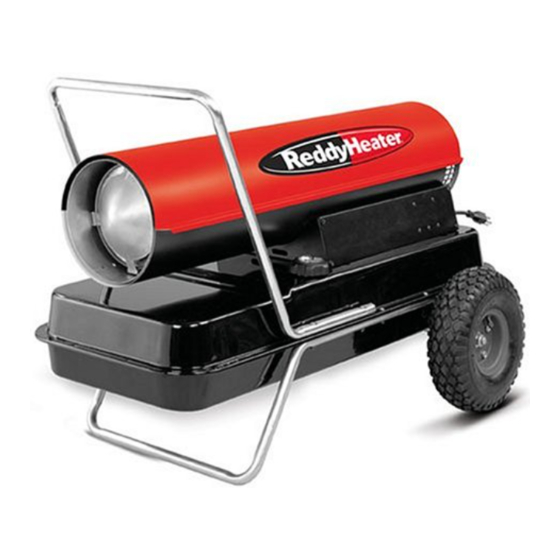
Upper Shell Lower Shell Fuel Tank Side Cover Flame-Out Control Reset Button Power Cord 35/50/70,000 BTU/HR DOMESTIC Figure 1 - 30/70,000 BTU/Hr Models Hot Air Outlet Lower Shell Fuel Cap Side Cover Figure 2 - 90,000 BTU/Hr Model Hot Air... -
Page 5: Unpacking
UNPACKING ASSEMBLY (For 90,000 and 150,000 BTU/Hr Models Only) 099606 1. Remove all packing items applied to heater for shipment. 2. Remove all items from carton. 3. Check items for any shipping damage. If heater is damaged, promptly inform dealer where you bought heater. These models are furnished with wheels and handles. -
Page 6: Theory Of Operation
THEORY OF OPERATION Clean Heated Air Out Fuel Tank FUELS The Fuel System: The air pump forces air through the air line. The air is then pushed through the burner head nozzle. This air causes fuel to lift from the tank. A fine mist of fuel is sprayed into the combustion chamber. -
Page 7: Ventilation
Up to 100 feet (30.5 meters) long, use 16 AWG (1.0 mm 101 to 200 feet (30.6 to 61 meters) long, use 14 AWG (1.5 mm Heater will start when power cord is plugged into outlet. If not, push in flame- out control reset button (see Figures 6 thru 8). -
Page 8: Storage
OPERATION Continued STORAGE PREVENTATIVE MAINTENANCE SCHEDULE Flame-Out Control Reset Button (Fan Guard Removed) Figure 8 - Flame-Out Control Reset Button, 150,000 BTU/Hr To Stop Heater 1. Unplug power cord from outlet. To Restart Heater 1. Wait 2 minutes after stopping heater. 2. -
Page 9: Troubleshooting
Continued TROUBLE- SHOOTING 099606 Item How Often Spark plug Clean and regap every 600 hours operation or replace as needed. Fan blades Clean every season or as needed. See Fan, page 19. Motor Not required/permanently lubricated Never service heater while it is plugged in, operating, or hot. Severe burns and electrical shock can occur. -
Page 10: Service Procedures
Shell 150 SHELL REMOVAL EA/EB Euro Figure 11 - Upper Shell Removal, 150,000 BTU/Hr Model Fuel Filter Side Cover Figure 12 - Fuel Filter Removal, 30/70,000 BTU/Hr Models WARNING Upper Shell Figure 10 - Upper Shell Removal, 90,000 BTU/Hr Model... -
Page 11: Fuel Filter (90,000 Btu/Hr Model)
Fuel Filter (90,000 BTU/Hr Model) 1. Remove side cover screws using 5/16" nut-driver. 2. Remove side cover. 3. Pull upper fuel line off fuel filter neck. 4. Carefully pry bushing, lower fuel line, and fuel filter out of fuel tank. 5. -
Page 12: Spark Plug (30,000 Btu/Hr Model)
Air Line Hose Figure 15 - Spark Plug Removal, 30,000 BTU/Hr Model Figure 16 - Spark Plug Gap, 30,000 BTU/Hr Model Burner Strap Figure 17 - Spark Plug Rotation, 30,000 BTU/Hr Model Only Burner Strap Spark Spark Plug Plug Wire... -
Page 13: Spark Plug (70/90/150,000 Btu/Hr Models)
Spark Plug (70/90/150,000 BTU/Hr Models) 1. Remove upper shell (see page 10). 2. Remove fan (see page 19). 3. Remove spark plug wire from spark plug. 4. Remove spark plug from burner head using 13/16" open-end wrench. 5. Clean and regap spark plug electrodes to .055"... -
Page 14: Air Output, Air Intake, And Lint Filters
4.4 PSI 150,000 BTU/Hr 4.9 PSI Air Intake Filter Filter End Cover Fan Guard Fan Guard Air Intake Filter (90,000 BTU/Hr Model Shown) Filter End Cover (30/70,000 BTU/Hr Models Shown) Relief Valve Pressure Gauge Figure 23 - Adjusting Pump Pressure 099606... -
Page 15: Nozzle (30,000 Btu/Hr Model)
12. Replace fan (see page 19). 13. Replace fan guard and upper shell. 099606 Combustion Chamber Air Line Hose Figure 24 - Removing Air and Fuel Line Hoses, 30,000 BTU/Hr Model Burner Strap Figure 25 - Removing Nozzle Assembly, 30,000 BTU/Hr Model Nozzle Face Nozzle... -
Page 16: Nozzle (70/90,000 Btu/Hr Models)
Nozzle (70/90,000 BTU/Hr Models) 1. Remove upper shell (see page 10). 2. Remove fan (see page 19). 3. Remove fuel and air line hoses from burner head. 4. Remove spark plug wire from spark plug. 5. Remove spark plug from burner head using 13/16"... -
Page 17: Nozzle (150,000 Btu/Hr Model)
Chamber Screw Air Line Hose Figure 29 - Removing Burner Head, 150,000 BTU/Hr Model Nozzle Face Nozzle Burner Head Figure 30 - Removing Nozzle, 150,000 BTU/Hr Model Spark Plug Wire Burner Head Flare Nut Fuel Tube Nozzle Seal Spark Plug... -
Page 18: Pump Rotor
16. Perform steps 10 thru 12 above. Insert Rotor Air Output Filter 50 ROTOR PFA/P 056 Figure 31 - Rotor Location, 30/70,000 BTU/Hr Models Insert Rotor Output 150 ROTOR PFA/P 059 Filter Figure 32 - Rotor Location, 90/150,000 BTU/Hr Models... -
Page 19: Fan
Setscrew Figure 35 - Fan, Motor Shaft, and Setscrew Location Motor Shaft Setscrew Figure 36 - Fan Cross Section Output Rating (BTU/Hr) 30,000 Fuel Use Only Kerosene or No. 1 Fuel Oil Fuel Tank Capacity (U.S. Gal./Liters) 3.0/11.35 Fuel Consumption (Gal. -
Page 20: Illustrated Parts Breakdown And Parts List
ILLUSTRATED PARTS BREAKDOWN 30,000 BTU/Hr 18-1 18-2 18-3 18-4 18-18 18-17 18-16 18-15 18-14 Motor and Pump Assembly 18-5 18-6 18-7 18-8 18-9 18-10 18-11 18-12 18-13 11-5 11-4 11-3 14 10 11-1 11-2 099606... - Page 21 PARTS LIST 30,000 BTU/Hr PART PART NUMBER DESCRIPTION M51104-01 Handle 098511-36 Upper Shell M15823-27 Screw, #10-16 x 1/2" 098512-05 Combustion Chamber M51108-01 Heat Shield M11084-29 Screw, #10-16 x 3/4" M16660 Photocell Bracket M10908-2 Screw, #6-32 x 3/8" HA3019 Photocell Assembly...
-
Page 22: 70,000 Btu/Hr Model
ILLUSTRATED PARTS BREAKDOWN 70,000 BTU/Hr 10-1 10-2 10-3 10-4 10-5 10-6 Burner Head Assembly 18-1 18-2 18-3 18-4 18-5 18-18 18-17 18-16 18-15 18-14 Motor and Pump Assembly MOTOR & PUMP 70 EAI/EBI PFA/P 007 10-7 18-6 18-7 18-8 18-9 18-10 18-11 18-12... - Page 23 PARTS LIST 70,000 BTU/Hr PART PART NUMBER DESCRIPTION M51104-01 Handle 098511-36 Upper Shell M15823-27 Screw, #10-16 x 1/2" 098512-12 Combustion Chamber M11084-29 Screw, #10-16 x 3/4" M16660 Photocell Bracket M10908-2 Screw, #6-32 x 3/8" HA3019 Photocell Assembly 079673-03 Power Cord Burner Head Assembly 10-1 M50880-01...
-
Page 24: 90,000 Btu/Hr Model
ILLUSTRATED PARTS BREAKDOWN 90,000 BTU/Hr BURNER HEAD 100 EAI/EBI Burner Head Assembly 13-1 13-3 13-2 13-4 13-18 13-17 13-16 13-15 13-14 Motor and Pump Assembly MOTOR & PUMP 100 EAI/EBI PFA/P 010 PFA/P 022 13-5 13-6 13-7 13-8 13-9 13-13 13-12 13-10 13-11... - Page 25 PARTS LIST 90,000 BTU/Hr PART PART NUMBER DESCRIPTION 098511-63 Upper Shell M15823-27 Screw, #10-16 x 1/2" 098512-07 Combustion Chamber M16660 Photocell Bracket HA3019 Photocell Assembly M27417 Drain Plug M10908-2 Screw, #6-32 x 3/8" Burner Head Assembly M23103 Nozzle M10659-1 Nozzle Seal Washer M10809-1 Nozzle Seal Spring M8882...
-
Page 26: 150,000 Btu/Hr Model
ILLUSTRATED PARTS BREAKDOWN 150,000 BTU/Hr BURNER HEAD 150 EAI/EBI PFA/P 028 Burner Head Assembly 22-1 22-2 22-3 22-4 22-18 22-17 22-16 22-15 22-14 MOTOR & PUMP 150 EAI/EBI PFA/P 013 Motor and Pump Assembly 22-5 22-6 22-7 22-8 22-9 22-10 22-11 22-13 22-12... - Page 27 PARTS LIST 150,000 BTU/Hr PART PART NUMBER DESCRIPTION 098511-29 Upper Shell 098068-01 Heat Deflector 098512-02 Combustion Chamber M16660 Photocell Bracket HA3019 Photocell Assembly 099125-02 Terminal Board M10908-2 Screw, #6-32 x 3/8" Burner Head Assembly M18022 Nozzle M10659-1 Nozzle Seal Washer M10809-1 Nozzle Seal Spring M8882...
-
Page 28: Wheels And Handles (90/150,000 Btu/Hr Models)
90,000 AND 150,000 BTU/Hr MODELS KEY PART NO. NUMBER ASSEMBLY, EURO WHEELS AND HANDLES FOR PART DESCRIPTION HA2203 Handles HA2205 Handles M12345-33 Screw, #10-24 x 1 3/4" M12342-3 Wheel Support Frame M12831-3 Wheel Support Frame NTC-3C Hex Nut, #10-24 097896-01 Wheel M28526 Cap Nut... -
Page 29: Wiring Diagrams
WIRING DIAGRAMS 099606 White Spark Plug Orange Ignitor Motor Green/ Yellow Figure 37 - Wiring Diagram, 30,000 BTU/Hr White Spark Plug Orange Ignitor Motor Green/ Yellow S or 2 M or 3 Black Motor Start Relay L or 1 Figure 38 - Wiring Diagram, 70/90,000 BTU/Hr... -
Page 30: Accessories
HEAVY DUTY WHEELS AND HANDLE KIT - HA1202 For heavy duty applications. Makes your heater even more portable and convenient. For 30/70,000 BTU/Hr models. STANDARD WHEELS AND HANDLE KIT - HA1206 Makes heater even more portable and convenient. Easy to assemble. - Page 31 NOTES 099606...
-
Page 32: Warranty And Repair Service
DESA International, or any alteration or repair by others in such manner as in DESA International's judgement affects the Product materially and adversely, shall void this Warranty.