Denon DRA-697CI Operating Instructions Manual
Am-fm stereo receiver
Hide thumbs
Also See for DRA-697CI:
- Service manual (54 pages) ,
- Manual (16 pages) ,
- Code list (10 pages)
Table of Contents
Advertisement
Advertisement
Table of Contents

Related Manuals for Denon DRA-697CI


Summary of Contents for Denon DRA-697CI
- Page 1 AM-FM STEREO RECEIVER DRA-697CI OPERATING INSTRUCTIONS...
-
Page 2: Safety Instructions
ENGLISH ¢SAFETY PRECAUTIONS CAUTION RISK OF ELECTRIC SHOCK DO NOT OPEN CAUTION: TO REDUCE THE RISK OF ELECTRIC SHOCK, DO NOT REMOVE COVER (OR BACK). NO USER-SERVICEABLE PARTS INSIDE. REFER SERVICING TO QUALIFIED SERVICE PERSONNEL. The lightning flash with arrowhead symbol, within an equilateral triangle, is intended to alert the user to the presence of uninsulated “dangerous voltage”... - Page 3 This product, when installed as indicated in the instructions contained in this manual, meets FCC requirements. Modification not expressly approved by DENON may void your authority, granted by the FCC, to use the product. 3. NOTE This product has been tested and found to comply with the limits for a Class B digital device, pursuant to Part 15 of the FCC Rules.
-
Page 4: Table Of Contents
ENGLISH Thank you for choosing the DENON DRA-697CI AM-FM Stereo Receiver. This remarkable component has been engineered to provide outstanding high fidelity reproduction of your favorite music sources. As this product is provided with an immense array of features, we recommend that before you begin hookup and operation that you review the contents of this manual before proceeding. -
Page 5: Before Using
Note Wall About the remote control unit In addition to controlling the DRA-697CI, the attached system remote control unit (RC-1052) can also be used to control the following products: q DENON component products w Component products other than DENON: •... -
Page 6: Part Names And Functions
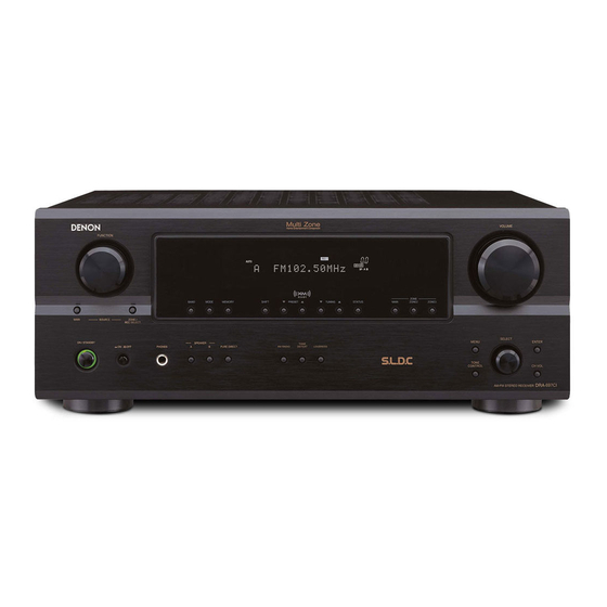
ENGLISH Getting Started Part names and functions For details on the functions of these parts, refer to the pages given in parentheses ( ). Front panel @5 @4 o !1 !2 Power operation button (ON/STANDBY) ··········································(12) Power indicator ·········································(12) Power switch ·······································(12, 21) Headphones jack (PHONES) ·····················(12) MODE button ·······································(14, 18) SPEAKER buttons ······································(12) -
Page 7: Rear Panel
Getting Started Rear panel !6 e !4 ! 3 AUDIO OUT terminals·································(7) AUDIO PRE OUT / MAIN IN terminals ····(10) SUBWOOFER PRE OUT terminal ···············(6) VIDEO IN terminals ·····································(7) AUDIO IN terminals·····························(6, 7, 9) VIDEO OUT terminals ·····························(6, 7) ZONE PRE OUT terminals···························(9) RS-232C terminal ·······································(10) TRIGGER OUT jacks ··································(10) SIGNAL GND terminal ································(7) -
Page 8: Connections
ENGLISH Getting Started [ Rear ] ZONE3 ON/OFF buttons ····························(20) ZONE2 ON/OFF buttons ····························(20) Number buttons (0 ~ 9, +10) ··········(14, 16, 22) BAND button ··················(14) Memory block buttons (A ~ G)···············(14) Function buttons············(12) MAIN ZONE ON/OFF buttons ····························(20) ¢ ZONE remote control unit (RC-1056) [ Front ] ZONE select switch········(20) Function buttons············(20) -
Page 9: Speaker Connections
Either tightly twist or terminate the the ventilation around the unit, switch off the core wires. power and contact a DENON service center. 3. Tighten by turning clockwise. Connecting banana plugs Turn clockwise to tighten, then insert the banana plug. -
Page 10: Connecting A Tv/Dbs Tuner
ENGLISH Connections Connecting a TV/DBS tuner Connecting a CD player Connecting a turntable • The phono input can accept signals from moving magnet (MM) and high output moving coil (MC) phono cartridges. If your turntable is equipped with a low output MC cartridge, you will need to use a separate MC head amplifier or step-up MC transformer. -
Page 11: Connecting The Antenna Terminals
Connecting the XM terminal • DRA-697CI is the XM Ready ® receiver. You can receive XM ® Satellite Radio by connecting to the XM Mini-Tuner and Home Dock (includes home antenna, sold separately) and subscribing to the XM service. -
Page 12: Connecting The Ipod
When using an iPod, you must connect the Control Dock for iPod (ASD-1R, sold separately) and the DOCK CONTROL jack on the DRA-697CI with a mini-jack and assign the iPod to any AUDIO terminal(s). The diagram below shows an example of connections for when the iPod is assigned to the CD-R/TAPE terminals. -
Page 13: Connecting The Trigger Out Jacks
Connections Connecting the TRIGGER OUT jacks Turn the DC 12 V voltage on and off for the individual functions. Connecting the RS-232C terminal This terminal is used for an external controller. Perform the following operation before using an external controller connected to the RS-232C terminal: 1. -
Page 14: Setup Menu
P o d : D V D ENGLISH Setting the Trigger Out Use the DC 12 V output of the DRA-697CI’s two trigger out jacks in association with the various input sources. MENU Press with the function set to something other “FM/AM”, “XM”... -
Page 15: Setting The High Pass Filter
Setup Menu Setting the High Pass Filter Set this to “ON” if your speakers do not have a very strong capacity for producing low bass. MENU Press with the function set to something other “FM/AM”, “XM” or the function selected at “iPod Assignment”. -
Page 16: Checking The Currently Playing Program Source, Etc
ENGLISH Operation FUNCTION MODE <PRESET> MENU BAND SHIFT TUNING <SELECT> STATUS <ON/STANDBY> PURE DIRECT <LOUDNESS> MEMORY <TONE DEFEAT> <TONE CONTROL> SHIFT [CHANNEL] [FM/AM] FUNCTION ENTER MENU [DIMMER] STATUS [VIDEO SELECT] PURE DIRECT [NUMBER] (0 ~ 9, +10) BAND [MEMORY BLOCK] MODE MEMORY FUNCTION... -
Page 17: Listening To The Radio
Operation Listening to the radio Check that the remote control unit is set to “A”. Auto preset memory This unit is equipped with a function for automatically searching for FM broadcast stations and storing them in the preset memory. MENU With the function set to “FM/AM”, press •... -
Page 18: Xm Satellite Radio
ENGLISH Operation FUNCTION STATUS XM RADIO TUNING XM RADIO FUNCTION ENTER [D H F G] STATUS [NUMBER] (0 ~ 9, +10) [SEARCH] FUNCTION TUNING About the button names in this explanation < > : Buttons on the main unit : Buttons on the remote control unit Button name only : Buttons on the main unit and remote control unit XM Satellite Radio... -
Page 19: Checking The Xm Signal Strength And Radio
Operation Checking the XM signal strength and Radio ID FUNCTION XM RADIO to select “XM” or press STATUS Press until “SIGNAL” is displayed. • The display changes as shown below according to the receiving condition. Display Condition GOOD Signal strength is good MARGINAL Signal strength is marginal WEAK... -
Page 20: Playing The Ipod
Violating copyrights is prohibited by law. • The optional standard Control Dock for iPod is DENON ASD-1R sold separately. • To assign to a different function after a function has already been assigned, switch to a function other than the one that is assigned then repeat the procedure. -
Page 21: Listening To Music In The Browse Mode
Information on the latest version of the software can be obtained on the Apple Computer website. • With the DRA-697CI it is possible to display folder names and file names on the screen like titles. The DRA-697CI can display up to 64 characters, consisting of numbers, capital letters and small letters. -
Page 22: Multi Zone Music Entertainment System
¢ When using the power amplifier as the MAIN ZONE output • The DRA-697CI is equipped with pre-out terminals for which the volume is adjustable and video output terminals (composite) as the ZONE2 (ZONE3) output terminals, and variable output level as the ZONE2 (ZONE3) output terminals. -
Page 23: Outputting A Program Source To Amplifier, Etc., In The Zone2 (Or Zone3) Room (Zone2 Or Zone3 Select Mode)
Operation FUNCTION <ZONE/REC SELECT> [CHANNEL] FUNCTION [VOLUME] [MODE SELECTOR 1] [MODE SELECTOR 2] [ZONE2 ON] [ZONE3 OFF] [ZONE2 OFF] [ZONE3 ON] FUNCTION [MAIN ON/OFF] About the button names in this explanation < > : Buttons on the main unit : Buttons on the remote control unit Button name only : Buttons on the main unit and remote control unit Outputting a program source to amplifier, etc.,... -
Page 24: Recording (Audio And/Or Video)
About the memory functions ¢ Last function memory The various settings set when the DRA-697CI’s power is switched to standby are stored in the memory. When the power is turned back on, the settings made when the power was switched to standby are recalled. -
Page 25: Operating The Remote Control Unit
Setting the preset memory function • DENON and other makes of components can be operated by setting the preset memory. • This remote control unit can be used to operate components of... - Page 26 ENGLISH Operating the remote control unit ¢ Functions of buttons for the different devices [Front] Device operated CD player or iPod (Monitor) MODE SELECTOR 1 MODE SELECTOR 2 CD/iPod Power off – Power on Power on Preset – TV channels – CHANNEL –...
- Page 27 TUNING + Tuning + TV volume + Tuning – TV volume – TUNING – Default setting DENON HITACHI (Preset code) (111) (134) Special remarks Special remarks: It is only possible to set the preset memory for one device per mode. When a new code is preset, the previous code is automatically deleted.
-
Page 28: Troubleshooting
• Insert batteries properly. in reverse. • The set’s internal temperature has • Put the DRA-697CI in a well- risen and the protection circuit has ventilated place. been activated. • Turn off the power, then wait for the set to fully cool off before turning the power back on. -
Page 29: Specifications
Specifications ¢ Audio section • Power amplifier Rated output: 100 W + 100 W (8 Ω/ohms, 20 Hz ~ 20 kHz with 0.08 % T.H.D.) Output terminals: A or B 4 ~ 16 Ω/ohms A + B 8 ~ 16 Ω/ohms •... - Page 30 ENGLISH ¢ List of preset codes Denon 014, *[111] Aiwa Hitachi 006, 011 Konka 012, 013 Magnavox Mitsubishi Panasonic Philips 005, 015, 016, 017 Pioneer 003, 008 Sanyo Sony 002, 019, 020 Toshiba 001, 021, 022 Zenith Denon 028, 029, 112...
- Page 31 Radix Technics Randex Teknika 007, 013, 019, 023, 058, 063, 064, 065, 073, 080, 082, 087 Toshiba Realistic 009, 021, 031, 033, 049, 053, 081, 087, 088, 091, Totevision 094, 097, 098 Unirech Ricoh Vecrtor Research Salora 033, 041 Victor Samsung 007, 011, 051, 059, 070, Video Concepts...
- Page 32 ENGLISH Philips Magnavox 005, 010, 017, 030, 033, 038, 050, 056, 071, 078, 079, 085, 089, 108, 109, Pioneer 110, 127, 131, 132, 145 Portland Marantz 015, 017, 071, 080 Price Club Matsui Proscan Memorex 014, 027, 045, 083, 118, Proton Pulsar Metz...
- Page 33 Teac Philips Technics Primestar Wards Proscan 048, 055, 056 Yamaha 048, 055, 056, 068 Zenith Realistic Sierra I Sierra II Denon Sierra III Philips Sony 049, 067 STS1 STS2 Denon STS3 Kenwood SRS4 Onkyo Technisat 077, 078, 079, 081, 082...
- Page 34 TOKYO, JAPAN www.denon.com Denon Brand Company, D&M Holdings Inc. Printed in China 00D 511 4538 007...