Brother HL-1440 Service Manual
Service manual
Hide thumbs
Also See for HL-1440:
- Brochure & specs (2 pages) ,
- Service manual (250 pages) ,
- User manual (116 pages)
Table of Contents
Advertisement
Quick Links
Advertisement
Table of Contents

Related Manuals for Brother HL-1440


Summary of Contents for Brother HL-1440
- Page 11 CLASS 1 LASER PRODUCT APPAREIL LASER DE CLASSE 1 LASER KLASSE 1 PRODUKT...
- Page 12 CAUTION INVISIBLE LASER RADIATION WHEN OPEN AND INTERLOCK DEFEATED. AVOID DIRECT EXPOSURE TO BEAM. CLASS 3B LASER PRODUCT. ADVARSEL USYNLIG LASER STRÅLING NÅR KABINETLÅGET STÅR ÅBENT. UNGDÅ DIREKTE UDSÆTTELSE FOR STRÅLING. KLASSE 3B LASER. VARNING OSYNLIG LASERSTRÅLNING NÄR DENNA DEL ÄR ÖPPNAD OCH SPÄRRAR ÄR URKOPPLADE.
-
Page 14: Chapter 1 General
12 pages per minute (ppm) print speed (A4 or Letter paper). <HL-1440> True 1200 x 600 dots per inch (dpi) for graphics and 600 x 600 dots per inch (dpi) (GDI mode) and true 300 x 300 dots per inch (dpi) (PCL mode) with microfine toner . Up to 14 pages per minute (ppm) print speed (A4 )and up to 15 pages per minute (ppm) print speed (Letter paper). -
Page 15: Environment-Friendly
<Sleep Mode (Power Save Mode)> Sleep mode automatically reduces power consumption when the printer is not in use for a certain period of time. The printer consumes less than 5W (HL-1230), 6W (HL-1440/1450) or 12W (HL-1470N) when in sleep mode. - Page 16 CHAPTER 1 GENERAL Bar Code Print (for HL-1450/1470N only) The printer can print the following 11 types of bar codes; Code 39 US-PostNet EAN-8 • • • Code 128 ISBN EAN-13 • • • Interleaved 2 of 5 UPC-A EAN-128 •...
-
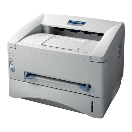
Page 17: Front View
Manual feed paper guides Manual feed slot Paper indicator Paper cassette Fig. 1-1 <Rear View> HL-1230/1440 Rear cover USB interface connector (for HL-1440 only) Parallel interface connector Power switch AC power inlet Fig. 1-2 HL-1450/1470N Network interface (for HL-1470N only) Network board... -
Page 18: Specifications
Normal printing mode Economy printing mode Print speed HL-1230: Up to 12 pages/minute HL-1440/1450/1470N: Up to 14 pages/minute* (when loading A4 from the paper cassette.) Up to 15 pages/minute (when loading letter-size paper from the paper cassette.) Warm-up Max. 25 seconds at 23°C (73.4°F) - Page 19 CHAPTER 1 GENERAL Life expectancy: 20,000 pages/drum unit *NOTE: Print speed varies depending on the paper size or media type. For details, refer to APPENDIX 3 ‘PRINT SPEEDS WITH VARIOUS SETTINGS’.
- Page 20 • iMac, Power Macintosh G3 with USB printer driver (for HL- 1440/1450/1470N only) • Bi-directional parallel Interface • Universal Serial Bus (USB) (for HL-1440/1450/1470N only) • 10/100 BaseTX Ethernet network interface (for HL-1470N only) Memory HL-1230 No memory expansion is possible HL-1440: 2.0 Mbytes of standard memory and a slot for...
-
Page 21: Electrical And Mechanical
(Under 25°C / 77°F) Printing (average): 340 W or less Standing by: 70 W or less Sleep*: 5 W or less (HL-1230) 6 W or less (HL-1440/1450) 12 W or less (HL-1470N) Noise Printing: 50 dB A or less Standing by: Silent... - Page 22 CHAPTER 1 GENERAL Network (for HL-1470N only ,Option for HL-1230/1440/1450 ) Type / Speed 10/100 Base TX Ethernet Auto speed detection Protocols • HL-1230/1440/1450 • TCP/IP,IPX/SPX,NetBEUI,DLC/LLC,DEC LAT,Banyan VINES • HL-1470N • TCP/IP,AppleTalk,PIPX/SPX,DLC/LLC • Web Based Management Management • BRAdmin Professional Windows based management utility •...
- Page 23 CHAPTER 1 GENERAL Paper 3.5.1 Feedable paper (1) Type & size Feeding source Paper type Paper size Paper cassette Normal paper A4, Letter, B5 (ISO), A5, A6, Executive, Legal* Transparencies Manual feed slot Normal paper A4, Letter, B5 (JIS/ISO), A5, A6, Executive, Legal 70-216 x 116-356 mm (2.75-8.5 x 4.57-14 inches) Envelopes...
- Page 24 CHAPTER 1 GENERAL • Avoid using coated paper such as vinyl coated paper. • Avoid using preprinted or highly textured paper. • It is recommended to use labels or transparencies which are designed for use in laser printers. • Avoid feeding labels with the carrier sheet exposed, or the printer will be damaged. •...
-
Page 25: Print Delivery
CHAPTER 1 GENERAL 3.5.2 Paper cassette capacity (1) Maximum load height Paper cassette: <Normal paper> Up to 27mm (1.06 inches) in height (250 sheets of 80 g/m A4/Letter paper) <Transparencies> 10 sheets (2) Paper feed conditions Manual feed Type Weight Cassette (1 sheet) 60 to 105 g/m... -
Page 26: Effective Printing Area
CHAPTER 1 GENERAL Printing Area 3.6.1 Effective printing area The effective printing area means the area within which the printing of all the data received without any omissions can be guaranteed. (1) Supported by the engine (2) Supported by the emulation 208mm 4.23mm 2,400 (80 characters) - Page 27 CHAPTER 1 GENERAL The table below shows the print guaranteed areas for each paper size. Size 210.0 mm 297.0 mm 203.2 mm 288.5 mm 3.4 mm 4.23 mm 8.27” 11.69” 8.0” 11.36” 0.13” 0.17” (2,480 dots) (3,507 dots) (2,400 dots) (3,407 dots) (40 dots) (50 dots)
- Page 29 Printer Paper cassettle Drum unit Documents (with Toner cartridge included) CD-ROM AC cord...
- Page 30 D:\START.EXE...
- Page 45 Drum Ready Paper Alarm Toner Data...
- Page 50 L-LED F-LED A-LED (green) (orange) (green)
-
Page 51: Theory Of Operation
THEORY OF OPERATION ELECTRONICS General Block Diagram HL-1230/1440 Fig. 3-1 shows a general block diagram of the HL-1230/1440 printer. Optional RAM (SIMM) (max. 32Mbytes) (HL-1440 only) Control system Expansion memory I/O RAM 2MB (HL-1440 only) Interface block (HL-1230: Parallel) Video control block... - Page 52 CHAPTER 3 THEORY OF OPERATION HL-1450 Fig. 3-2 shows a general block diagram of the HL-1450 printer. Optional RAM (SIMM) (max. 32Mbytes) Control system Expansion RAM 4MB memory I/O Interface block (Parallel/USB) Video control block Engine control block Operation block (Control panel) Paper tray unit Drive block...
- Page 53 CHAPTER 3 THEORY OF OPERATION HL-1470N Fig. 3-3 shows a general block diagram of the HL-1470N printer. Network board Optional RAM (SIMM) Ethernet (max. 32Mbytes) 10/100 Base TX Control system Expansion RAM 4MB PCI bus memory I/O Interface block (Parallel / USB) Video control block Engine control block Operation block...
-
Page 54: Main Pcb Block Diagram
Program + Font ROM 1.0 Mbytes Timer (2.0 Mbytes) FIFO Option RAM (SIMM) CDCC Parallel I/O To PC (max.32Mbytes) (HL-1440 only) To PC USB I/O (HL-1440 only) Soft Support EEPROM (128 8 bits) EEPROM I/O Engine Control I/O To Engine PCB Fig. 3-4... - Page 55 CHAPTER 3 THEORY OF OPERATION HL-1450 Fig. 3-5 shows the block diagram of the main PCB of the HL-1450 printer. A S I C CPU Core (MB86832) Oscillator (33.33MHz) Reset Circuit Address Decoder DRAM Control Program + Font ROM 8.0 Mbytes Timer (4.0 Mbytes) FIFO...
- Page 56 CHAPTER 3 THEORY OF OPERATION HL-1470N Fig. 3-6 shows the block diagram of the main PCB of the HL-1470N printer. A S I C CPU Core (MB86832) Reset Circuit Oscillator (33.33MHz) Address Decoder DRAM Control Program + Font ROM 8.0 Mbytes Timer Flash ROM (2.0 Mbytes)
- Page 57 (nibble mode, byte mode, ECP mode). (2) USB interface (for HL-1440 only) Stores the data received from the PC into DRAM as controlled by the DMA controller. The transmission speed is 12Mbps.
- Page 58 CHAPTER 3 THEORY OF OPERATION HL-1450/1470N A Fujitsu 32bit RISC CPU, MB86832 (SPARC lite) is built in the ASIC. While the CPU is driven with a clock frequency of 33 MHz in the user logic block, it itself runs at 66 MHz, which is generated by multiplying the source clock by two.
- Page 60 CHAPTER 3 THEORY OF OPERATION 1.3.2 HL-1230/1440 An 8 Mbits ROM (x 16 bit) is fitted. Fig. 3-9 HL-1450 Two 64 Mbits ROMs (x 32 bit) are fitted. Fig. 3-10 3-10...
- Page 61 CHAPTER 3 THEORY OF OPERATION HL-1470N Two 32 Mbits ROMs (x 16 bit) are fitted. Fig. 3-11 3-11...
- Page 62 CHAPTER 3 THEORY OF OPERATION 1.3.3 Flash ROM (for HL-1470N only) HL-1470N Two 8 Mbits flash ROMs (x 16 bit) are fitted. Fig. 3-12 1.3.4 DRAM HL-1230/1440 A 16M-bit DRAM (x 16 bits) is used as the RAM. Fig. 3-13 3-12...
- Page 63 CHAPTER 3 THEORY OF OPERATION HL-1450/1470N Two 16M-bit DRAMs (x 16 bits) are used as the RAM. Fig. 3-14 3-13...
-
Page 64: Optional Ram
CHAPTER 3 THEORY OF OPERATION 1.3.5 Optional RAM HL-1440 A 32bit (72 pin) SIMM can be fitted as optional RAM. The main PCB has one slot and the capacity of SIMM can be from 1 Mbyte to 32 Mbytes. Fig. 3-15... - Page 65 CHAPTER 3 THEORY OF OPERATION HL-1450/1470N A 32bit (72 pin) SIMM can be fitted as optional RAM. The main PCB has one slot and the capacity of SIMM can be from 1 Mbyte to 32 Mbytes. Fig. 3-16 3-15...
- Page 66 CHAPTER 3 THEORY OF OPERATION 1.3.6 PCI bus HL-1470N The interface of the PCI bus is PCI specification revision 2.2 compliant. Fig. 3-17 3-16...
-
Page 67: Reset Circuit
CHAPTER 3 THEORY OF OPERATION 1.3.7 EEPROM HL-1230/1440 The EEPROM is X24C01A type of two-wire method with a 128 x 8 bits configuration. Fig. 3-18 HL-1450 The EEPROM is X24C04 type of two-wire method with a 512 x 8 bits configuration. Fig. - Page 68 CHAPTER 3 THEORY OF OPERATION HL-1450/1470N The reset IC is a RN5VD42A. The reset voltage is 4.2V (typ.) and the LOW period of reset is 80ms (typ.) Fig. 3-22 1.3.9 Engine I/O HL-1230/1440 Fig. 3-22 shows the engine interface circuit. The interface with the engine PCB is by full- duplex synchronous serial method.
-
Page 69: Engine Pcb
CHAPTER 3 THEORY OF OPERATION Engine PCB The gate array which transforms the serial signal from the main PCB into the parallel signal is mounted on the engine PCB. The engine PCB controls the following parts by using the transferred signal data; Toner sensor Main motor •... -
Page 70: Low-Voltage Power Supply
CHAPTER 3 THEORY OF OPERATION Power Supply 1.6.1 Low-voltage power supply The power supply uses a switching regulation system to generate the regulated DC power (+5V and +24V), which are converted from the AC line. The regulated output and the production code of each power supply are listed below; Regulated Output Production Code +5V / 1.6 A... -
Page 71: High-Voltage Power Supply
CHAPTER 3 THEORY OF OPERATION 1.6.2 High-voltage power supply The high-voltage power supply generates and outputs the voltages and currents for the charging, development and transfer functions. For the circuit diagram of the high-voltage power supply PCB, see Appendix Current 24VI Regulator Transfer Roller... - Page 73 CHAPTER 3 THEORY OF OPERATION Laser Unit Network Laser Cover Sensor (B) Board (HL-1470N) Polygon Motor Drum Unit Primary Charger (Corona Wire) Engine Main PCB High- Primary Charger (Grid) Front Registration Voltage Sensor Power Development Roller Supply Rear Registration Sensor Supply Roller Upper Paper Low-Voltage...
-
Page 74: Paper Registration
CHAPTER 3 THEORY OF OPERATION Paper Transfer 2.2.1 Paper supply The paper pick-up roller picks up one sheet of paper from the paper cassette every time it is rotated and feeds it to the paper feed roller. Pinch roller Paper feed roller Paper pick-up roller Front registration Pinch roller... -
Page 75: Paper Eject
CHAPTER 3 THEORY OF OPERATION 2.2.3 Paper eject After the printing image on the photosensitive drum is transferred onto the paper, the paper is fed to the fixing unit to fix unfixed toner onto the paper. Afterwards, the paper is ejected from the fixing unit by the first eject roller in the fixing unit. The eject sensor lever detects whether the paper is ejected correctly or not. -
Page 76: Toner Sensor
CHAPTER 3 THEORY OF OPERATION Sensors 2.3.1 Cover sensors A and B Detect opening and closing of the front cover. Cover sensor (B) Cover sensor (A) Fig. 3-32 2.3.2 Toner sensor Detects if there is toner in the toner cartridge. The toner sensor at the left side emits light through the window on the left side of the toner cartridge, then the toner sensor at the right side receives it when the toner is low. -
Page 77: Toner Cartridge
CHAPTER 3 THEORY OF OPERATION Drum Unit 2.4.1 Photosensitive drum Generates the latent electrostatic image and develops the image on the drum surface. 2.4.2 Primary charger Forms a uniform charge on the drum surface. (1) Corona wire Generates the ion charge on the drum. (2) Grid Spreads the ion charge evenly over the drum surface. -
Page 78: Exposure Stage
CHAPTER 3 THEORY OF OPERATION Print Process 2.6.1 Charging The drum is charged to approximately 870V by an ion charge which is generated by the primary charger. The charge is generated by ionization of the corona wire, which has a DC bias from the high-voltage power supply applied to it. - Page 79 CHAPTER 3 THEORY OF OPERATION The area exposed to the laser beam is the image to be printed. The surface potential of the exposed area is reduced, forming the electrostatic image to be printed. 1 Cycle of drum Primary charging Laser beam exposure and developing (a) Unexposed area +870...
-
Page 80: Fixing Stage
CHAPTER 3 THEORY OF OPERATION 2.6.4 Transfer (1) Transfer process After the drum has been charged and exposed, and has received a developed image, the toner formed is transferred onto the paper by applying a negative charge to the back of the paper. - Page 82 MAIN PCB ASSY PAPER CASSETTE PCB ASSY (HL-1250/1270N only) NETWORK BOARD LOW-VOLTAGE (HL-1270N only) PS PCB ASSY SIMM (HL-1440/1450/1470N only) PANEL PCB ASSY ENGINE PCB ASSY / HIGH-VOLTAGE PS PCB ASSY FRONT COVER TONER SENSOR TOP COVER PCB ASSY (emission)
- Page 131 4-43...
-
Page 133: Chapter 5 Periodic Maintenance
CHAPTER 5 PERIODIC MAINTENANCE CHAPTER 5 PERIODIC MAINTENANCE To avoid creating secondary problems by mishandling, follow the warnings below during maintenance work. WARNING (1) Always turn off the power switch and unplug the power cord from the power outlet before accessing any parts inside the printer. (2) Some parts inside the printer are extremely hot immediately after the printer is used. -
Page 134: Toner Cartridge
CHAPTER 5 PERIODIC MAINTENANCE (4) Install the toner cartridge into the new drum unit until it locks into place, indicated by a click. When the toner cartridge is installed correctly, the lock lever is lifted automatically. (Fig. 5-2) (5) Install the new drum unit into the printer. Check that the printer is turned on, the front cover is open and the Drum and Alarm LEDs illuminate. - Page 135 CHAPTER 5 PERIODIC MAINTENANCE (4) Remove the protective cover. (Fig. 5-4) (5) Install the new toner cartridge into the drum unit until it locks into place, indicated by a click. When the toner cartridge is installed correctly, the lock lever is lifted automatically. Fig.
-
Page 136: Periodical Replacement Parts
CHAPTER 5 PERIODIC MAINTENANCE PERIODICAL REPLACEMENT PARTS Periodical replacement parts are the parts to be replaced periodically to maintain product quality. These parts would affect the product quality greatly if they lost their function even if they do not appear to be damaged or there is no change in their appearance.) The periodical replacement parts listed below should be replaced at the service center referring to the service life. -
Page 137: Periodical Cleaning
CHAPTER 5 PERIODIC MAINTENANCE PERIODICAL CLEANING Clean the following parts periodically to avoid any printer problems or print image defects. CAUTION: While drum unit and scanner window cleaning basically can be implemented by the end user, the electrical terminals inside the printer and on the drum unit should be cleaned by a service technician. -
Page 138: Cleaning The Scanner Window
CHAPTER 5 PERIODIC MAINTENANCE Cleaning the Scanner Window When replacing the drum unit or toner cartridge with a new one, be sure to clean the scanner window. Turn off the power switch and unplug the power cord. Remove the drum unit from the printer. Gently wipe the scanner window (colored magenta in the figures below) with a soft dry cloth. - Page 139 CHAPTER 5 PERIODIC MAINTENANCE MTBF / MTTR The meantime between failure (MTBF) and the meantime to repair (MTTR) for this printer are as follows; MTBF: Up to 4,000 hours MTTR: Average 30 minutes...
- Page 143 Error occurs. Confirm the LED indication. Turn OFF/ON the power switch. Error occurs again. Temporary error. See Section 6 Use the printer with- 'Malfunction'. out corrective action.
- Page 144 Drum Ready Paper Alarm Toner Data Time delay : OFF : Blinking...
-
Page 159: Malfinctions
+ lead pin - lead pin Voltage P5-2 P5-3 Approx. 24V Engine Approx. 5V P3-10 P3-9... - Page 164 I-5 Dirt on back of paper I-1 Light I-2 Dark I-2 Dark I-3 Completely blank I-4 All black I-6 Black vertical I-6 Black vertical I-7 Black horizontal I-8 Black vertical I-9 White vertical streaks streaks stripes streaks streaks Print out test print out test print out test Print out test print o Print out test print out test print out test Print out test print o Print out test print o Print out test print out test print out test Print out test print o Print out test print out test print out test Print out test print o Print out test print o...
- Page 174 Print out test print out test print out test Print out test print o Print out test print out test print out test Print out test print o Print out test print o Print out test print out test print out test Print out test print o Print out test print out test print out test Print out test print o Print out test print o Print out test print out test print out test Print out test print o Print out test print out test print out test Print out test print o Print out test print o...
- Page 186 Print Server Status Control...
- Page 188 /etc/ethers /etc/hosts /etc/printcap /usr/spool :lp = /dev/null: \ :lp = :\...
- Page 189 SET SERVICE BRN_xxxxxx_P1 EOT 2 SET SERVICE BRN_xxxxxx_P1 EOT 3 /etc/printcap mx#0 etc/printcap...
- Page 190 PRINT QUEUE INFORMATION CURRENTLY ATTACHED SERVERS SET NETWARE PASSWORD...
- Page 191 NETWARE SERVER servername ENABLED SET NETWARE FRAME...
- Page 192 SET APPLETALK ZONE...
- Page 195 Drum Toner sensor Ready Rear registration sensor Paper Alarm Front registration sensor Toner Data Upper paper cassette sensor (HL-1450/1470N) Button pressed...
- Page 205 Drum Life 100% 00000090909090909 99.4% MZ-L160003F000000...
- Page 206 Value in units of 1,000 (Refer to the list below.)
- Page 209 APPENDIX Note that each maintenance information is counted under the conditions below; Information Conditions Drum unit change When drum unit life is 100 pages or more, and the drum counter is reset. (Maximum counter: 63) Toner cartridge change When the toner cartridge is replaced after a Toner Empty error is stored in NVRAM, then warming-up completes without a Toner Empty or Toner Low error being detected.
-
Page 216: Toner Cartridge Weight Information
APPENDIX PR2002109 APPENDIX 8. TONER CARTRIDGE WEIGHT INFORMATION Toner Cartridge Weight (approx weight) TN6300 / TN430 TN6600 / TN460 Brand new Toner Cartridge Weight 775 g 820 g Toner Weight at Brand New Toner Cartridge 145 ± 5g 190 ± 5g Toner Cartridge Weight at Toner Near Empty 720 ~ 725 g 720 ~ 725 g... -
Page 217: Laser Unit
Appendix 8. Connection Diagram, HL-1230 AC INPUT INLET PARALLEL I/F LVPS MAIN PCB POWER PAPER EJECT SENSOR CN101 LASER POLYGON MOTOR MOTOR LASER UNIT MAIN MOTOR GRID HVPS ENGINE PCB SOLENOID REAR REGISTRATION SENSOR PANEL PCB FRONT REGISTRATION SENSOR TONER SENSOR TONER (light emission) - Page 218 Appendix 9. Connection Diagram, HL-1440 AC INPUT INLET PARALLEL I/F (HL-1440 only) LVPS MAIN PCB POWER SIMM PAPER EJECT SENSOR CN101 LASER POLYGON MOTOR MOTOR LASER UNIT MAIN MOTOR GRID HVPS ENGINE PCB SOLENOID REAR REGISTRATION SENSOR PANEL PCB FRONT REGISTRATION...
- Page 219 Appendix 10. Connection Diagram, HL-1450 AC INPUT INLET PARALLEL I/F LVPS MAIN PCB POWER SIMM PAPER EJECT SENSOR CN101 LOWER PAPER CASSETTE LASER POLYGON MOTOR MOTOR LASER UNIT MAIN MOTOR GRID HVPS ENGINE PCB SOLENOID REAR REGIST SENSOR PANEL PCB UPPER PAPER CASSETTE FRONT REGIST...
-
Page 220: Connection Diagram Hl-1470N
Appendix 11. Connection Diagram, HL-1470N RJ45 (Ethernet) AC INPUT NETWORK BOARD INLET PARALLEL I/F P21PCI LVPS MAIN PCB POWER SIMM PAPER EJECT SENSOR CN101 LOWER PAPER CASSETTE LASER POLYGON MOTOR MOTOR LASER UNIT MAIN MOTOR GRID HVPS ENGINE PCB SOLENOID REAR REGIST SENSOR PANEL PCB... - Page 226 R130 D202 C201 R209 R210 VR201 R116 R114 R113 VR101 C204 R111 D201 R214 R110 C207 R206 D105 R115 C111 R208 D104 R202 R203 R204 C101 C206 R215 C302 J105 C102 NTC1 BEA1...
-
Page 227: Low-Voltage Power Supply Pcb Circuit Diagram
R130 D202 C201 R210 R209 VR201 R116 R114 R113 VR101 C204 R111 D201 R214 R110 C207 R206 D105 R115 C111 R208 D104 R202 R203 R204 C101 C206 R215 C302 J105 C102 NTC1 BEA1... -
Page 228: High-Voltage Power Supply Pcb Circuit Diagram
Appendix 19. High-voltage Power Supply PCB Circuit Diagram, ZLe (MPH3212) CODE NAME...