
Related Manuals for Panasonic BTLH80W - 7.9" MONITOR


Summary of Contents for Panasonic BTLH80W - 7.9" MONITOR
-
Page 1: Operating Instructions
Operating Instructions LCD Video Monitor BT-LH80WP Model No. BT-LH80WE Model No. Before operating this product, please read the instructions carefully and save this manual for future use. ENGLISH S0507N0 -M Printed in Japan VQT1H75... -
Page 2: Read This First! (For Bt-Lh80Wp)
Read this first! (For BT-LH80WP) FCC Note: CAUTION This equipment has been tested and RISK OF ELECTRIC SHOCK found to comply with the limits for a class DO NOT OPEN A digital device, pursuant to Part 15 of the FCC Rules. These limits are designed CAUTION: TO REDUCE THE RISK OF ELECTRIC SHOCK, DO NOT REMOVE COVER (OR BACK). -
Page 3: Read This First! (For Bt-Lh80We)
Read this first! (For BT-LH80WE) DO NOT REMOVE PANEL COVERS BY CAUTION: UNSCREWING THEM. In order to maintain adequate ventilation, do To reduce the risk of electric shock, do not not install or place this unit in a bookcase, remove the covers. No user serviceable parts built-in cabinet or any other confined space. -
Page 4: Table Of Contents
Contents Read this first! (For BT-LH80WP) ....2 User Data ....... . . 15 Read this first! (For BT-LH80WE) . -
Page 5: Precautions For Use
Precautions for use This product has been specially designed for commercial use. As such, it should be used and operated only by persons with related expertise. The liquid crystal parts are fabricated using high-precision technology. The screen has effective pixels that cover more than 99.99% of its area, but pixels may be missing or remain permanently lighted (red, blue and/or green) in less than 0.01% of the area. -
Page 6: Outline
It is equipped with a 7.9-inch V (effective display area) liquid crystal display panel. It can be used as a VF (viewfinder) for broadcasting and business cameras made by Panasonic. Equipped with a new IP conversion circuit, the circuit processing greatly reduces time delays A new I/P conversion circuit has been introduced that converts and generates SD and HD interlace signals to high-precision progressive signals without generating time delays per field. -
Page 7: Controls And Their Functions
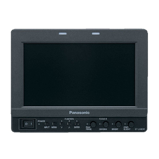
Controls and Their Functions Front panel FUNCTION FOCUS-R POWER PEAK/ CONT/ INPUT MENU ENTER PHASE CHROMA BRIGHT B.LIGHT POWER switch/lamp This switches the power supply ON/OFF. When the power is ON, the LED (green) lights up. INPUT SELECT button This selects the signal input line. Each time the button is pressed, the input changes in the following order: →... -
Page 8: Rear Panel
(analog component signal) input terminal. VF terminal (D-SUB, 15 pins) This terminal connects to the VF (viewfinder) terminal of broadcasting and business cameras made by Panasonic. The unit can be used as the viewfinder for such a camera. GPI input terminal (D-SUB, 9 pins) External control is possible by using a GPI signal. -
Page 9: Supplying The Power
Supplying the power An Anton/Bauer or V-mount type of battery pack or an external DC power supply can be used to power this monitor. Using the Anton/Bauer type battery pack Using a V-mount type battery pack Install the Anton/Bauer type of battery pack. CAUTION: These servicing instructions are for use by qualified Battery pack... -
Page 10: Using An External Dc Power Supply
Supplying the power (continued) Using an external DC power supply Connect the external DC power supply to the DC IN DC IN socket socket on this unit. 1: GND DC IN socket 4: +12 V <Notes> • Use a shield cable with a length of 2 m (6.56 feet) or less for the DC cable. -
Page 11: Vf Function
VF Function The unit can be connected to broadcasting and business cameras made by Panasonic and used as a VF (viewfinder). VF cable (Option) DC cable (Option) BT-LH80W DC cable ∗ VF cable (Option) (Option. Camera platform ∗ Part number:... -
Page 12: How To Use The On Screen Menu
How to Use the On Screen Menu Six types of information are displayed on the screen: the operating status display, picture adjusting knob status, sharpness display, function display, DC power supply voltage display, battery level display and menu display. Operating status display 1. -
Page 13: Sharpness Display
How to Use the On Screen Menu (continued) Sharpness display • SHARPNESS H/V is displayed when it is set. • The display disappears if remains idle for 2 minutes. SHARPNESS H 30 Function display • You can set FUNCTION display in the menu. •... -
Page 14: Menu Operations
How to Use the On Screen Menu (continued) Menu operations 1. Push [MENU] to display the MAIN menu. 3. Push [ ] to select the sub menu, then push [ENTER]. The setting values in the sub menu change to green. FUNCTION [MARKER] MARKER... -
Page 15: User Data
User Data You can change the menu setting values and picture adjusting knob settings, then save and load up to 5 combinations of screen adjustment values as user data. You can also return the setting values and adjustment values to the factory preset settings. -
Page 16: Main Menu
Main Menu Menu configuration MAIN MENU MARKER MARKER 16:9 VIDEO CONFIG COLOR TEMP. SHARPNESS MODE BACK CONT./BACK. SYSTEM CONFIG SHARPNESS H CENTER BACKLIGHT SHARPNESS V GPI PRESET1 PEAKING/PHASE I-P MODE GPI PRESET2 STATUS DISPLAY MONO BATTERY REMAIN USER 63 SD ASPECT SETUP LOAD SETUP SAVE PWR ON SETUP... -
Page 17: Marker
Main Menu (continued) MARKER The underlined values are factory preset setting values. Sub menu Settings Explanation OFF ∗ MARKER Used to make MARKER settings effective. 16:9 ∗ ∗ Used to select/display the type of marker when the aspect ratio setting is 16:9. -
Page 18: Types Of Marker
Main Menu (continued) Types of MARKER 16:9 marker 4:3 marker (Displayed when using HD, or when using SD (Displayed when using SD with a 4:3 aspect ratio) with a 16:9 aspect ratio) A dotted line is displayed as the marker. The marker is only displayed as a vertical bar. -
Page 19: Video Config
Main Menu (continued) VIDEO CONFIG The underlined values are factory preset setting values. Sub menu Settings Explanation USER 63 ∗ COLOR TEMP. Used to select the color temperature. <USER 0 - 63> Adjustable settings 0 - 63 (color temperature around 3000K - 9300K) <D93>... - Page 20 Main Menu (continued) About IP Mode By selecting “MODE1”, you can convert IP through Frame Interpolation. This unit has reduced the Frame Interpolation delay to 1 field or less, compared to our old models having caused 1 frame delay or more. Factory preset setting value is “MODE1”...
-
Page 21: System Config
Main Menu (continued) SYSTEM CONFIG The underlined values are factory preset setting values. Sub menu Settings Explanation CONT. /BACK. BACKLIGHT Used to select the function to be assigned to CONT/B.LIGHT (a knob CONTRAST on the front panel). <BACKLIGHT> Used to adjust BACKLIGHT. <CONTRAST>... -
Page 22: Vf Config
INPUT SELECT menu (→ page 29). (Input lines that are set with RETURN CH are enabled even if they are set to OFF in INPUT SELECT.) ∗ 2 A function to be used with future Panasonic camera-recorders. -
Page 23: Function
Main Menu (continued) FUNCTION The underlined values are factory preset setting values. Sub menu Settings Explanation FUNCTION1 - 3 BLUE ONLY Used to select the functions to be assigned to individual buttons SD ASPECT ∗ ∗ [FUNCTION1] to [FUNCTION3] (front-panel buttons). <BLUE ONLY>... - Page 24 Main Menu (continued) Restrictions on various FUNCTION settings Under the following conditions, various settings are disabled. Setting Disabling condition SD ASPECT Does not operate while GPI items are being set. Does not operate during PIXEL TO PIXEL operation. Does not operate during HD display. If operated during the conditions described above, “INVALID FUNCTION”...
- Page 25 Main Menu (continued) About WFM You can display the wave form monitor using the “WFM” function. The display changes each time you press one of the buttons, [FUNCTION1] to [FUNCTION3] (→ page 23), assigned with the [WFM] function (To use the “WFM” function, you must assign it to one of the [FUNCTION1] to [FUNCTION3] buttons).
- Page 26 Main Menu (continued) Display position sequence during an HD signal 1080i input PIXEL POS.+: 1)→2)→3)→4)→5)→6)→7)→8)→9)→1) · · · · · PIXEL POS.–: 1)→9)→8)→7)→6)→5)→4)→3)→2)→1) · · · · · 1) CENTER 2) LEFT TOP 3) MID TOP 4) RIGHT TOP 5) RIGHT MID 6) RIGHT BOTTOM 7) MID BOTTOM 8) LEFT BOTTOM...
- Page 27 Main Menu (continued) About FOCUS-IN-RED When the FOCUS-IN-RED function is used, the section that is being focused is displayed in an easy-to-understand red, making camera focus adjustments easy. Each time the button from [FUNCTION1] to [FUNCTION3] to which the FOCUS-IN-RED function is assigned is pushed, the display is switched (the FOCUS-IN-RED function must be assigned to one of the buttons from [FUNCTION1] to [FUNCTION3] in order to be able to use the FOCUS-IN-RED function).
-
Page 28: Gpi
Main Menu (continued) The “GPI CONTROL” item is used to set enable/disable of all GPI functions, and assigns functions to each of the GPI terminal pins (→ page 31). The underlined values are factory preset setting values. Sub menu Settings Explanation GPI CONTROL DISABLE... -
Page 29: Input Select
Main Menu (continued) INPUT SELECT The underlined values are factory preset setting values. Sub menu Settings Explanation line to the INPUT SELECT button. ∗ Used to set the YP COMPONENT SMPTE Used to select the input level for the YP (component) signal. -
Page 30: Control
Main Menu (continued) CONTROL The underlined values are factory preset setting values. Sub menu Settings Explanation CONTROL LOCAL Used to select the operation. (Combined control lock) REMOTE <LOCAL> Front operation enabled <REMOTE> Remote operation enabled (The front controls become locked) ∗ LOCAL DISABLE When “REMOTE”... -
Page 31: Remote Specifications
REMOTE Specifications REMOTE operation is possible on this monitor using the GPI/RS-232C terminal. GPI terminal Each of the items in the GPI screen are compatible with the following terminals. You can assign functions to each terminal in the menu GPI screen (→ page 28). The functions assigned to each terminal operate when the GND (Pin 5) is connected (ON) or open (OFF). -
Page 32: Rs-232C Terminal
REMOTE Specifications (continued) Assignment of item priority levels • When both “MARKER1” and “MARKER2” are ON at the same time, “MARKER1” has priority. However, when the display aspect is 4:3, the “MARKER1” aspect is 16:9, and the “MARKER2” aspect is 4:3, “MARKER2” is displayed. - Page 33 REMOTE Specifications (continued) Setting command No. Command Explanation Data Response Input switch 0: SDI 2: VIDEO 3: YP 5: VF Image quality CON00-60 : Contrast settings adjustment BRI00-60 : Brightness settings CRO00-60 : Chroma settings PHA00-60 : Phase settings Blue only 0: OFF 1: ON Backlight settings...
- Page 34 REMOTE Specifications (continued) Query command No. Command Explanation Data Response Input selection 0: SDI 2: YP 4: VIDEO 7: VF-YP 8: VF-VIDEO Image quality CON: Contrast setting value 00-60 adjustment BRI: Brightness setting value 00-60 CRO: Chroma setting value 00-60 PHA: Phase setting value 00-60 Blue only...
-
Page 35: Maintenance Inspections
Maintenance Inspections Maintenance inspections are necessary for the user to use this equipment safely. It is important to keep monitor functions in good condition at all times through periodical and appropriate maintenance. In order to use this monitor for a long time, and to make full use of all of its functions, be sure to carry out the following maintenance inspections. 1. -
Page 36: Error/Warning Displays
Error/Warning Displays If for any reason an error occurs in the unit, the user is alerted of error or warning with the following displays. Error/Warning Display Solution Inverter error All the lamps on the side of Switch the power supply OFF once, then switch it picture adjusting knobs flash at back ON again. - Page 37 Specifications (continued) List of compatible signal formats ( : Compatible, : Limited compatibility) Input signal SDI ∗ VIDEO VF-VIDEO VF-YP formats NTSC 480/59.94i 480/59.94P 576/50i 576/50P 720/50P 720/59.94P 720/60P ∗ ∗ ∗ 1035/59.94i ∗ ∗ ∗ 1035/60i 1080/23.98PsF 1080/24PsF 1080/50i 1080/59.94i 1080/60i ∗...
- Page 38 San Gabriel Industrial Park, 65th Infantry Ave., Km. 9.5, Carolina, Puerto Rico 00630 (787) 750-4300 Professional & Broadcast IT Systems Business Unit Europe Panasonic AVC Systems Europe a Division of Panasonic Marketing Europe GmbH Hagenauer Str. 43, 65203 Wiesbaden-Biebrich Deutschland Tel: 49-611-235-481...