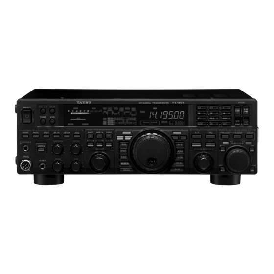
Yaesu FT-950 Operating Manual
Hf/50 mhz transceiver
Hide thumbs
Also See for FT-950:
- Technical supplement (155 pages) ,
- Manual (16 pages) ,
- Brochure & specs (12 pages)
Table of Contents
Advertisement
Quick Links
HF/50 MH
T
Z
RANSCEIVER
FT-950
O
M
PERATING
ANUAL
VERTEX STANDARD CO., LTD.
4-8-8 Nakameguro, Meguro-Ku, Tokyo 153-8644, Japan
VERTEX STANDARD
US Headquarters
10900 Walker Street, Cypress, CA 90630, U.S.A.
YAESU EUROPE B.V.
P.O. Box 75525, 1118 ZN Schiphol, The Netherlands
YAESU UK LTD.
Unit 12, Sun Valley Business Park, Winnall Close
Winchester, Hampshire, SO23 0LB, U.K.
VERTEX STANDARD HK LTD.
Unit 5, 20/F., Seaview Centre, 139-141 Hoi Bun Road,
Kwun Tong, Kowloon, Hong Kong
VERTEX STANDARD ( AUSTRALIA ) PTY., LTD.
Normanby Business Park, Unit 14/45 Normanby Road
Notting Hill 3168, Victoria, Australia
Advertisement
Chapters
Table of Contents

Related Manuals for Yaesu FT-950


Summary of Contents for Yaesu FT-950
- Page 1 4-8-8 Nakameguro, Meguro-Ku, Tokyo 153-8644, Japan VERTEX STANDARD US Headquarters 10900 Walker Street, Cypress, CA 90630, U.S.A. YAESU EUROPE B.V. P.O. Box 75525, 1118 ZN Schiphol, The Netherlands YAESU UK LTD. Unit 12, Sun Valley Business Park, Winnall Close Winchester, Hampshire, SO23 0LB, U.K.
- Page 2 ANUAL The FT-950 is a leading-edge transceiver with a number of new and exciting features, some of which may be unfamiliar to you. In order to gain the most enjoyment and operating efficiency from your FT-950, we recommend that you read this manual in its entirety, and keep it handy for reference as you explore the many capabilities of your new transceiver.
-
Page 3: General Description
FT-1000 keys are provided for band selection. Each band key pro- series, the FT-950 provides up to 100 Watts of power out- vides three separate VFO settings for three different parts put on SSB, CW, and FM (25 Watts AM carrier). Digital of each band. -
Page 4: Table Of Contents
Quick Split Operation ........69 More Frequency Navigation Techniques ....39 Keyboard Frequency Entry ......39 Using the [CLAR/VFO-B] knob ...... 39 Using the UP/DOWN switches of the supplied MH-31 Hand Microphone ..39 Page 2 FT-950 O PERATING ANUAL... - Page 5 Choosing the Desired Memory Group ..... 95 Operation on Alaska Emergency Frequency: 5167.5 kHz (U.S. Version Only) ........ 96 VFO and Memory Scanning ........97 VFO Scanning ............97 Memory Scan ............98 PMS (Programmable Memory Scan) ....... 99 FT-950 O Page 3 PERATING ANUAL...
-
Page 6: Accessories & Options
& O CCESSORIES PTIONS UPPLIED CCESSORIES Hand Microphone ( MH-31 1 pc A07890001 DC Power Cord 1 pc T9025225 Spare Fuse (25A) 1 pc Q0000074 Operating Manual 1 pc Warranty Card 1 pc Page 4 FT-950 O PERATING ANUAL... -
Page 7: Available Options
CT Cable (MDIN6P - MDIN6P 2m) Antenna Rotator Connection Cable (P/N T9101556) CT Cable (MDIN10P - Bare Wire 2m) Linear Amplifier Connection Cable (P/N T9207451) MD-200 YH-77STA FH-2 VL-1000/VP-1000 DMU-2000 RF μTuning Kit FC-40 DVS-6 FT-950 O Page 5 PERATING ANUAL... -
Page 8: Before You Begin
Available adjustment range is 120°. Hold the Skirt TIGHTEN LOOSEN Page 6 FT-950 O PERATING ANUAL... -
Page 9: Resetting The Microprocessor
[ POWER ] button [ LOCK ] button MPORTANT When the optional μTuning Kit is connected to the FT- 950, disconnect all the cables from the μTuning Kit be- fore performing the Full Reset. FT-950 O Page 7 PERATING ANUAL... -
Page 10: Installation And Interconnections
Any antenna to be used with the FT-950 must be fed from the transceiver with 50 Ohm coaxial cable. Therefore, when using a “balanced” antenna such as a dipole, remember that a balun or other matching/balancing device must be used to ensure proper antenna performance. -
Page 11: Grounding
NSTALLATION AND NTERCONNECTIONS ROUNDING The FT-950 transceiver, like any other HF communications apparatus, requires an effective ground system for maximum electrical safety and best communications effectiveness. A good ground system can contribute to station efficiency in a number of ways: It can minimize the possibility of electrical shock to the operator. -
Page 12: Connection Of Antenna And Power Cables
Do not install the FT-950 on an unstable desk or table. Do not place in a location where objects may fall onto it from above. To minimize the possibility of interference to home entertainment devices, take all precautionary steps including sepa- ration of TV/FM antennas from Amateur transmitting antennas to the greatest extent possible, and keep transmitting coaxial cables separated from cables connected to home entertainment devices. -
Page 13: Connection Of Microphone And Headphone
NSTALLATION AND NTERCONNECTIONS ONNECTION OF ICROPHONE AND EADPHONE FT-950 O Page 11 PERATING ANUAL... -
Page 14: Key, Keyer, And Computer-Driven Keying
NTERCONNECTIONS The FT-950 includes many features for the CW operator. These functions will be detailed in the “Operation” section later. Besides the built-in Electronic Keyer, two key jacks are provided, one on the front and one on the rear panel, for convenient connection to keying devices. -
Page 15: Vl-1000 Linear Amplifier Interconnections
INEAR MPLIFIER NTERCONNECTIONS Be sure that both the FT-950 and VL-1000 are turned off, then follow the installation recommendations contained in the illustration. Please refer to the VL-1000 Operating Manual for details regarding amplifier operation. Please do not attempt to connect or disconnect coaxial cables when your hands are wet. -
Page 16: Interfacing To Other Linear Amplifiers
Amplifier systems utilizing different ALC voltages will Color Code Information LINEA Jack ( Pin Number ) Wire Color Function not work correctly with the FT-950, and their ALC Orange +13.8 V lines must not be connected if this is the case. Yellow... -
Page 17: Plug/Connector Pinout Diagrams
Please do not connect any accessory or other device not specifically approved by Vertex Standard. Failure to observe this precaution may cause damage not covered by the Limited Warranty on this apparatus. SIGNAL FT-950 O Page 15 PERATING ANUAL... -
Page 18: Front Panel Controls & Switches
[ POWER ] Switch [ TUNE ] Switch Press and hold in this switch for two seconds to turn This is the on/off switch for the FT-950’s Automatic the transceiver on. Similarly, press and hold in this Antenna Tuner. switch for two seconds to turn the transceiver off. - Page 19 2000) is connected, you may use the Audio Scope/ Oscilloscope page to help you adjust the setting of the compression level of the Speech Processor for optimum performance using your voice and micro- phone. FT-950 O Page 17 PERATING ANUAL...
-
Page 20: Microphone Connector
This 8-pin jack accepts input from a microphone uti- Indicates the final amplifier drain current. ID ID ID ID ID: lizing a traditional YAESU HF transceiver pinout. VDD: Indicates the final amplifier drain voltage. COMP: Indicates the speech compressor level (SSB... -
Page 21: Key Jack
Press the [ SELECT ] knob briefly and the indicator will blink. Pressing the button once to toggle the μ-Tuning function on/off. more will restore receiver operation, and the indicator will glow green steadily. FT-950 O Page 19 PERATING ANUAL... - Page 22 (±5.0 kHz Dev./25.0 kHz BW) hold in the [ C.S ] button for one second; this will lock and narrow (±2.5 kHz Dev./12.5 kHz BW). in the selected Menu item as the short cut. Page 20 FT-950 O PERATING ANUAL...
- Page 23 ” icon ap- the double beep) copies the current operating data into pears in the display. the currently selected memory channel, overwriting any previous data stored there. DVICE This switch affects VFO-A and VFO-B independently. FT-950 O Page 21 PERATING ANUAL...
- Page 24 Momentarily: RTTY ( LSB ) PKT ( LSB ) Press & Hold: RTTY ( LSB ) RTTY ( USB ) or PKT ( LSB ) PKT ( USB ) PKT ( LSB ) ..PKT ( FM ) Page 22 FT-950 O PERATING ANUAL...
- Page 25 Clarifier offset, press the [ CLEAR ] button. [ CLEAR ] Switch Pressing this button clears out any frequency offset you have programmed into the Clarifier register (thereby setting the offset to “Zero”). FT-950 O Page 23 PERATING ANUAL...
-
Page 26: Display Indications
(Forward: Reflected), from 1.0 to 3.0. Indicates the final amplifier drain current, 0 to 30 ampere. Indicates the final amplifier drain voltage (nominal value: 13.8 V). COMP Indicates the speech compressor level, from 0 to 30 dB. Page 24 FT-950 O PERATING ANUAL... - Page 27 [ R.FLT ] button. Graphically indicates the peak position of the DSP IF AGC ( AUTO, FAST, MID, SLOW ) : filter. Indicates the AGC decay time setting, selected by the front panel [ AGC ] switch. FT-950 O Page 25 PERATING ANUAL...
-
Page 28: Frequency Display
FAST is activated. This indicator appears when the Main Tuning Dial knob’s, tuning rate is set to “fast”. This indicator appears when the FT-950 is in the LOCK Memory Recall mode. This indicator appears when the Main Tuning Dial knob is locked. -
Page 29: Rear Panel
Peak signal level is 30 mVp-p at 10 This covered 6-pin MINI-DIN Jack accepts a cable to kOhms. connect to a YAESU Antenna Rotator Control, G- REM ( REMOTE ) Jack 800DXA, 1000DXA, or 2800DXA (listed models are current as of middle 2007). You may control the an-... - Page 30 [ AF GAIN ] knob. Inserting a plug into this jack This 9-pin serial DB-9 jack allows external computer disables the internal loudspeaker. control of the FT-950. Connect a serial cable here and KEY Jack to the RS-232C COM port on your personal computer This 1/4-inch 3-contact jack accepts a CW key or keyer (no external interface is required).
-
Page 31: Basic Operation: Receiving On Amateur Bands
If using a linear amplifier, have all interconnections been successfully completed? See page 13 for details. Please rotate the [ AF GAIN ] control to the fully counter-clockwise position, to avoid a loud blast of audio when the transceiver turns on. See page 23 for details. FT-950 O Page 29 PERATING... - Page 32 3. The transceiver will start up on 7.000.00 MHz LSB, 1.8 and 50 MHz is provided. and normal operation may begin. The FT-950 utilizes a triple band-stack VFO se- lection technique, which permits you to store up to To turn power off, press and hold in the front panel three favorite frequencies and modes onto each [ POWER ] switch for two seconds.
- Page 33 [ 100 Hz ] [ 100 kHz ] FM/PKT ( FM ) 100 Hz [ 1 kHz ] 100 kHz [ 1 MHz ] [ ] : [ FAST ] switch set to “ON” FT-950 O Page 31 PERATING ANUAL...
-
Page 34: (U.s. Version Only)
ETER VERSION ONLY The FT-950 includes the capability for transmission and reception on the five spot frequencies assigned to the Amateur Service in the United States. To operate on the 5 MHz band: 1. Press the [ V/M ] button once to enter the “Memory”... -
Page 35: Clar (Clarifier) Operation
VFO-A frequency (the Clarifier does not affect VFO-B). Four small numbers on the Multi-Display Window show the current Clarifier offset. The Clarifier controls on the FT-950 are designed to allow you to preset an offset (up to ±9.990 kHz) without actually retuning, and then to activate it via the Clarifier’s [ RX CLAR ] and [ TX CLAR ] buttons. -
Page 36: Lock
3. Rotate the [ CLAR/VFO-B ] knob to select the desired [ MENU ] Button [ CLAR/VFO-B ] Knob illumination level. 4. Press and hold in the [ MENU ] button for one second to save the new setting and exit to normal operation. Page 34 FT-950 O PERATING ANUAL... -
Page 37: Convenience Features
084 TUN DIALSTP” and “085 TUN CW FINE 085 TUN CW FINE”. See 084 TUN DIALSTP 084 TUN DIALSTP 084 TUN DIALSTP 085 TUN CW FINE 085 TUN CW FINE 085 TUN CW FINE page 116. FT-950 O Page 35 PERATING ANUAL... -
Page 38: My Bands" Operation
7 MHz 7 MHz 21 MHz 10 MHz 3.5 MHz 3.5 MHz 28 MHz 14 MHz 7 MHz 18 MHz 14 MHz 21 MHz 21 MHz 24 MHz 28 MHz 28 MHz 50 MHz Page 36 FT-950 O PERATING ANUAL... -
Page 39: Band Stack Operation
PERATION The FT-950 utilizes a triple band-stack VFO selection technique, that permits you to store up to three favorite frequencies and modes onto each band’s VFO register. For example, you may store one frequency each on 14 MHz CW, RTTY, and USB, then recall these VFOs by successive, momentary presses of the [ 14 ] MHz band button. -
Page 40: Rotator Control Functions
ONTROL UNCTIONS When using a YAESU model G-800DXA, G-1000DXA, or G-2800DXA rotator (not supplied), it is possible to control it from the front panel of the FT-950. 1. Press and hold in the [ ENT ] button (one of the [ BAND ] [ 3.5 ( 2 )] , [ 7 ( 3 )] Button... -
Page 41: More Frequency Navigation Techniques
[ MHz ] button will glow orange in the latter case. When tuning in 1 MHz steps, clockwise rotation of the [ CLAR/VFO-B ] knob will increase the frequency, while counter-clockwise rotation will decrease the frequency. FT-950 O Page 39 PERATING ANUAL... -
Page 42: Interference Rejection
LOCK IAGRAM The FT-950 includes a wide range of special features to suppress the many types of interference that may be encountered on the HF bands. However, real world interference conditions are constantly changing, so optimum setting of the controls is somewhat of an art, requiring familiarity with the types of interference and the subtle effects of some of the controls. -
Page 43: Att
IPO should be disabled and the [ ATT ] button should be set to “OFF.” This situation is typical during quiet times on frequencies above 21 MHz, and when using a small or negative-gain receiving antenna on other bands. FT-950 O Page 41 PERATING... -
Page 44: Μ-Tune Filter
006 DISP BARSEL”. See Box on 006 DISP BARSEL 006 DISP BARSEL 006 DISP BARSEL Press the [ SELECT ] knob (momentarily) once more, the next page for details of the setting. the μ-Tune filter is activated again. Page 42 FT-950 O PERATING ANUAL... - Page 45 (μ-Tune)” (replacing the default “C-tn C-tn (CW TUN- C-tn C-tn C-tn ING)” selection). 4. Press and hold in the [ MENU ] button for one sec- ond to lock in the new setting and exit to normal operation. FT-950 O Page 43 PERATING ANUAL...
-
Page 46: Ipo (Intercept Point Optimization)
If you can hear band noise with the preamplifiers disengaged, then a preamplifier is gen- erally not needed. The IPO feature is always on “IPO ON” (No RF pream- plifier) between 30 kHz and 1.7 MHz. Page 44 FT-950 O PERATING ANUAL... -
Page 47: R.flt (Roofing Filters)
How- ever, you still may override the automatic setting, and select a narrower Roofing Filter. Noise blanking may be compromised, however, with a tighter Roofing Fil- ter in the line. FT-950 O Page 45 PERATING ANUAL... -
Page 48: If Noise Blanker (Nb) Operation
IF N OISE LANKER PERATION The FT-950 includes an effective IF Noise Blanker, which can significantly reduce noise caused by automotive ignition systems. 1. Press the [ NB ] button momentarily to reduce short [ NB ] Button duration pulse noise such as from switching transients, automobile ignitions and power lines. -
Page 49: Contour Control Operation
“shoulder” of the passband response may be altered, or components may be removed from within the passband, allowing the desired signal to rise above the background noise and interference in a manner not obtainable with other filtering systems. FT-950 O Page 47... -
Page 50: If Shift Operation
[ SELECT ( SHIFT )] knob. The interference level is reduced by moving the filter passband so that the interference is outside of the passband. Desired Signal Desired Signal Desired Signal BANDWIDTH BANDWIDTH BANDWIDTH Page 48 FT-950 O PERATING ANUAL... -
Page 51: Width (If Dsp Bandwidth) Tuning
CW Mode: 500 Hz ~ 2.4 kHz (default: 2.4 kHz) later) may also be used, in conjunction with these RTTY/PKT Modes: 500 Hz ~ 2.4 kHz (default: filter systems, to significant advantage. 500 Hz) FT-950 O Page 49 PERATING ANUAL... -
Page 52: Narrow (Nar) One-Touch If Filter Selection
[ NAR ] button instead of adjustment of the [ SELECT ( WIDTH )] knob, may be satisfactory for interference reduction. When you press the [ NAR ] button in the FM mode, both transmit and receive bandwidths are narrowed. Page 50 FT-950 O PERATING ANUAL... -
Page 53: If Notch Filter Operation
[ SELECT ( NOTCH )] knob to eliminate the incom- NOTCH filter, which will appear as a white area in the ing interference. colored background area. Desired Signal Desired Signal (Heterodyne) (Heterodyne) BANDWIDTH BANDWIDTH FT-950 O Page 51 PERATING ANUAL... -
Page 54: Digital Notch Filter (Dnf) Operation
3 above. The “ ” icon will turn off, confirming that the DNR system is not active. DVICE The Digital Noise Reduction will be memorized indepen- dently on each VFO stack of VFO-A and VFO-B. Page 52 FT-950 O PERATING ANUAL... -
Page 55: Rf Gain (Ssb/Cw/Am Modes)
Thereafter, the RF Gain and Attenuator fea- tures may be employed to provide precise, delicate adjustment of the receiver gain to fully optimize per- formance. FT-950 O Page 53 PERATING ANUAL... -
Page 56: Tools For Comfortable And Effective Reception
EATURE There may be occasions when you want to silence the receiver audio of the FT-950, perhaps to concentrate on another receiver or telephone call. The Mute feature makes this simple to accomplish. -
Page 57: Agc (Automatic Gain Control)
AGC also protects the RF, IF, Audio, and DSP stages from overload, as it limits the sig- selections until you are thoroughly familiar with the per- formance of the FT-950. nal strength that is allowed to flow, irrespective of the in- put signal level. -
Page 58: Ssb/Am Mode Transmission
(carrier) power output of 25 Watts via the Menu item “112 TGEN AM CAR 112 TGEN AM CAR”. See Box on the 112 TGEN AM CAR 112 TGEN AM CAR 112 TGEN AM CAR next page for details of the setting. Page 56 FT-950 O PERATING ANUAL... - Page 59 Four techniques for exercising Transmit/Receive con- ALC meter deflection may be caused by excessive drive trol are provided on the FT-950. You may choose the power, but also by reflected power detected in the an- technique(s) that best suit your operating needs: tenna system.
-
Page 60: Using The Automatic Antenna Tuner
UNER The Automatic Antenna Tuner (hereinafter referred to as the “ATU”) built into each FT-950 is designed to ensure a 50- Ohm load for the final amplifier stage of the transmitter. We recommend that the ATU be used whenever you operate on the FT-950. -
Page 61: About Atu Operation
The “ ” icon will light up, and the tuner settings, if achieved, will not be memorized. Please investigate the high SWR condition and resolve the problem, before attempting further operation using this antenna. FT-950 O Page 59 PERATING ANUAL... -
Page 62: Enhancing Transmit Signal Quality
QUALIZER MODE The FT-950 includes a unique Three-Band Parametric Microphone Equalizer that provides precise, independent control over the low, mid and treble ranges in your voice waveform. You may utilize one group of settings when the speech processor is off and an alternate group of settings when the speech processor is on. The speech processor feature is de- scribed in the next chapter. - Page 63 “098 tAUd EQ3-LVL” ( Low ) “1” ~ “10” Q ( Bandwidth ) “093 tAUd EQ1-BW” ( Mid ) “1” ~ “10” “096 tAUd EQ2-BW” ( High ) “1” ~ “10” “099 tAUd EQ3-BW” +10dB FT-950 O Page 61 PERATING ANUAL...
-
Page 64: Using The Speech Processor
ROCESSOR ODES The FT-950’s Speech Processor is designed to increase “talk power” by increasing the average power output, (via a sophisticated compression technique) and adjusting the audio quality to the menu settings (“100 TAUD PE1 FRQ 100 TAUD PE1 FRQ”, “103... -
Page 65: Adjusting The Ssb Transmitted Bandwidth
When the optional DMU-2000 Data Management Unit is connected, you may verify the effect of your adjust- ments of the transmitted bandwidth by observing the Audio Scope on the “Oscilloscope” page. FT-950 O Page 63 PERATING ANUAL... -
Page 66: Transmitter Convenience Features
EMORY You may utilize the Voice Memory capability of the FT-950 for repetitive messages. The Voice Memory system includes five memories capable of storing up to 20 seconds of voice audio each. The maximum that any memory can hold is 20 seconds. -
Page 67: Recording Own Voice In Memory
EMORY Voice Memory Operation from the optional FH-2 Remote Control Keypad You may also utilize the Voice Memory capability of the FT-950 from the optional FH-2 Remote Control Keypad, which plugs into the rear panel’s REM jack. Recording Your Own Voice in Memory Checking Your Recording 1. -
Page 68: Vox (Automatic Tx/Rx Switching Using Voice Control)
114 TGEN VOX SEL” (the selections are 114 TGEN VOX SEL 114 TGEN VOX SEL 114 TGEN VOX SEL the new setting and exit to normal operation. “niC niC (MIC)” and “dAtA dAtA (DATA)”). dAtA dAtA dAtA Page 66 FT-950 O PERATING ANUAL... -
Page 69: Monitor
Because the Monitor feature samples the transmitter IF signal, it can be very useful for checking the adjust- ment of the Speech Processor or Parametric Equalizer on SSB, and for checking the general signal quality on AM and FM. FT-950 O Page 67 PERATING ANUAL... -
Page 70: Split Operation Using The Tx Clarifier
Yaesu transceivers with capa- offset from the original VFO frequency will appear in bility similar to that of your FT-950. On the DX side of the small display window. the pile-up, everyone calling precisely on the same CW... -
Page 71: Split-Frequency Operation
REQUENCY PERATION A powerful capability of the FT-950 is its flexibility in Split Frequency operation using the VFO-A and VFO-B frequency registers. This makes the FT-950 especially useful for high-level DX-peditions. The Split operation capability is very advanced and easy to use. -
Page 72: Cw Mode Operation
CW M PERATION The powerful CW operating capabilities of the FT-950 permit operation using an electronic keyer paddle, a “straight key”, or a computer-based keying device. ETUP FOR TRAIGHT TRAIGHT EY EMULATION PERATION Before starting, connect your key line(s) to the front and/or rear panel KEY jack(s). Be sure the [ KEYER ] button on the left side of the front panel is turned off for now. -
Page 73: Using The Built-In Electronic Keyer
(or a string of dots and dashes) will be transmit- ted. When you release the keyer paddle contacts, trans- mission will cease, and reception will be restored after a brief delay. The delay time is user-programmable, per the discussion on page 76. FT-950 O Page 71 PERATING ANUAL... -
Page 74: Full Break-In (Qsk) Operation
EYER Full Break-in (QSK) Operation As shipped from the factory, the FT-950 TX/RX system for CW is configured for “Semi-break-in” operation. However, using Menu item “043 A1A BK-IN 043 A1A BK-IN,” you may change this setup for full break-in (QSK) operation, whereby... -
Page 75: Selecting The Keyer Operating Mode
The configuration of the Electronic Keyer may be customized independently for the front and rear KEY jacks of the FT-950. This permits utilization of Automatic Character Spacing (ACS), if desired. This permits the use of an electronic keyer via the front jack and a straight key or computer-driven keying line via the rear panel jack. -
Page 76: Cw Convenience Features
DX station. From the DX offset pitch may be set to any frequency between 300 side, if a dozen or more operators (also using Yaesu’s Hz and 1050 Hz, in 50 Hz steps. You can either match... -
Page 77: Using Cw Reverse
CW Reverse is engaged. Normal CW Carrier Retune: Shift to Lower Frequency Zero-In RX Passband Retune: Shift to Higher Frequency CW Reverse Carrier RX Passband FT-950 O Page 75 PERATING ANUAL... -
Page 78: Cw Delay Time Setting
0 Hz tone). Therefore, the receiver is offset sev- eral hundreds of Hz (typically), to allow your ear to detect the tone. The BFO offset associated with this tuning (that produces the comfortable audio tone) is called the CW Pitch. Page 76 FT-950 O PERATING ANUAL... - Page 79 CW C ONVENIENCE EATURES FT-950 O Page 77 PERATING ANUAL...
-
Page 80: Contest Memory Keyer
EMORY EYER The FT-950 is capable of automatically sending CW messages (as you might do in a contest). Two techniques for message storage are available: you may either send the desired message contents using your keyer paddle (“Message Memory”), or you may input the text characters using the Main Dial Tuning knob and [ CLAR/VFO-B ] knobs (“Text Memory”). -
Page 81: Transmitting In The Beacon Mode
3. Press the [ SELECT ] knob momentarily. Repeti- tive transmission of the Beacon message will be- gin. Press the [ SELECT ] knob once more to halt the Beacon transmissions. FT-950 O Page 79 PERATING ANUAL... -
Page 82: Text Memory
[ MENU ] Button [ CLAR/VFO-B ] Knob [ CLAR/VFO-B ] Knob Main Tuning Dial Knob Message Cursor CW Memory Register Number DVICE Momentarily pressing the [ SELECT ] button will cancel the programming. Page 80 FT-950 O PERATING ANUAL... - Page 83 \ \ \ \ \ < % % % % % , , , , , = = = = = ^ ^ ^ ^ ^ & > _ _ _ _ _ ‘’’ ‘}’ FT-950 O Page 81 PERATING ANUAL...
-
Page 84: Contest Number Programming
EMOTE ONTROL EYPAD You may also utilize the CW message capability of the FT-950 from the optional FH-2 Remote Control Keypad, which plugs into the rear panel REM jack. Message Memory Five memory channels capable of retaining 50 characters total are provided (using the PARIS standard for characters and word length). - Page 85 037 A1A F-TYPE 037 A1A F-TYPE or “039 A1A R-TYPE 039 A1A R-TYPE” to “ACS ACS” (Automatic Character 039 A1A R-TYPE 039 A1A R-TYPE 039 A1A R-TYPE Spacing) while you are programming the keyer memories. FT-950 O Page 83 PERATING ANUAL...
-
Page 86: Text Memory
Menu items (#019 ~ 023) to “tyP1 tyP1 tyP1”. tyP1 tyP1 4. Press and hold in the [ MENU ] button for one second to save the new settings and exit. Page 84 FT-950 O PERATING ANUAL... - Page 87 Dial knob to select the last correct letter in the message. Now use the FH-2’s [ ] and [ ] keys or rotate the [ CLAR/VFO-B ] knob to select the “}” character; everything after the “}” character will be deleted. FT-950 O Page 85 PERATING ANUAL...
- Page 88 Contest Number will be reduced by one. Press the FH-2’s [ DEC ] key as many times as necessary to reach the desired number. If you go too far, use the “Contest Number Programming” technique de- scribed previously. LOCK Page 86 FT-950 O PERATING ANUAL...
-
Page 89: Fm Mode Operation
FM is only used in the 28 MHz and 50 MHz Amateur bands covered by the FT-950. Please do not use FM on any other bands. FT-950 O... -
Page 90: Repeater Operation
FM M PERATION EPEATER PERATION The FT-950 may be utilized on 29 MHz and 50 MHz repeaters. 1. Rotate the Main Tuning Dial knob to the output fre- [ MOX ] Button [ MODE ] Button Main Tuning Dial Knob quency (downlink) from the repeater. -
Page 91: Tone Squelch Operation
A “T T T T T ” notation on the “10 Hz” frequency digit while transmitting will indicate that the Tone Squelch is en- gaged. DVICE The Tone Squelch operation will be memorized indepen- dently on each VFO stack of the VFO-A and VFO-B. FT-950 O Page 89 PERATING ANUAL... -
Page 92: Memory Operation
UICK OINT The FT-950’s memory channels store the following data (not just the operating frequency): VFO-A Frequency VFO-A Mode Clarifier status and its Offset Frequency... -
Page 93: Qmb (Quick Memory Bank)
If you do not over-write the contents of the current memory channel, the original contents will not be disturbed by the initiation of Memory Tune operation. FT-950 O Page 91 PERATING ANUAL... -
Page 94: Standard Memory Operation
PERATION The Standard Memory of the FT-950 allows storage and recall of up to 99 memories, each storing frequency, mode, and a wide variety of status information detailed previously. Memories may be grouped into as many as six Memory Groups, and additionally you get nine pairs of band-limit (PMS) memories along with five QMB (Quick Memory Bank) memories. -
Page 95: Checking Memory Channel Status
4. Press the [ LOCK ] button to erase the contents of the [ CLAR/VFO-B ] Knob selected memory channel. [ A M ] Button DVICE The FT-950 can not erase the memory channels “01 01” (and “US1 US1” through “US5 US5”: U.S. version). -
Page 96: Moving Memory Data To
Tune” mode so closely resembles the VFO mode. Be sure desired. that you have the FT-950 operating in a control mode com- 3. Press the [ V/M ] button momentarily to return to the patible with your software’s requirements. Use the VFO originally memorized frequency of the current memory mode if you’re not sure. -
Page 97: Memory Groups
5. Rotate the [ CLAR/VFO-B ] knob to select the desired Memory Channel within the Selected Memory Group. DVICE If no channels have been assigned to a particular Memory Group, you will not have access to that Group. FT-950 O Page 95 PERATING ANUAL... -
Page 98: Operation On Alaska Emergency Frequency
The FT-950 includes the capability for transmission and reception on 5167.5 kHz under such emergency conditions via the Menu system. To activate this feature: 1. -
Page 99: Vfo And Memory Scanning
EMORY CANNING You may scan either the VFO or the memories of the FT-950, and the radio will halt scanning on any station with a signal strong enough to open the receiver’s squelch. VFO S CANNING 1. Set the VFO-A to the frequency on which you would [ VFO-B ( RX )] Button like to begin scanning. -
Page 100: Memory Scan
5SEc” setting will cause the scanner to 5SEc 5SEc 5SEc resume scanning after five seconds. However, you may change this setting to resume only after the carrier has dropped out, if you like. See page 111. Page 98 FT-950 O PERATING ANUAL... -
Page 101: Pms (Programmable Memory Scan)
9. If you press the microphone’s PTT switch during scan- ning, the scanner will halt at once. Pressing the PTT switch during scanning will not cause transmission. FT-950 O Page 99 PERATING ANUAL... -
Page 102: Packet Operation
ACKET PERATION Packet operation is easily accomplished on the FT-950 by connecting your TNC (Terminal Node Controller) to the trans- ceiver, per the illustration. “Packet” operation also applies to SSB-based AFSK data modes, such as PSK31, etc. DC IN INPUT: DC 13.8 V... -
Page 103: Rtty (Radio Teletype) Operation
111 TGEN TX PWR”. 111 TGEN TX PWR UICK OINT In the FT-950, “RTTY” is a mode defined as being an DVICE “FSK” mode, whereby the closing and opening of a key- If you need to adjust the output level from the “DATA ing line (to ground) causes the Mark/Space tones to alter- OUT”... -
Page 104: Miscellaneous Afsk-Based Data Modes
AFSK-B ISCELLANEOUS ASED ODES The FT-950 may also be used for a host of other SSB-based Data modes. Please set up your system using the illustration as a guideline. DC IN INPUT: DC 13.8 V 22 A -TUNE -TUNE FROM... -
Page 105: Menu Mode
Note FT-950 O Page 103 PERATING ANUAL... - Page 106 The Menu system of the FT-950 provides extensive customization capability, so you can set up your transceiver just the way you want to operate it. The Menu items are grouped by general utilization category, and are numbered from “001 AGC...
- Page 107 048 A1A PC KYNG MODE-CW 049 A1A QSKTIME 15/20/25/30 msec 15 msec 1: Requires optional DMU-2000 Data Management Unit. 2: Requires optional Antenna Rotator. 3: Requires optional DVS-6 Voice Memory Unit. 4: Requires optional RF μTuning Kit. FT-950 O Page 105 PERATING ANUAL...
- Page 108 5 kHz TUNING 088 TUN FM STEP 5/6.25/10/12.5/20/25 kHz 5 kHz TUNING 089 TUN FM DIAL 10/100 Hz 100 Hz TUNING 090 TUN MY BAND 1.8 ~ 50/GE 1: Requires optional DMU-2000 Data Management Unit. Page 106 FT-950 O PERATING ANUAL...
-
Page 109: About The Transverter Output Terminal
30 ~ 3000 msec ( 10 msec/step ) TX GENERAL 116 TGEN VOX DLY 500 msec TX GENERAL 117 TGEN ANTIVOX 0 ~ 100 EnA/diS ( ENABLE/DISABLE ) diS ( DISABLE ) TX GENERAL 118 TGEN EMRGNCY FT-950 O Page 107 PERATING ANUAL... -
Page 110: Agc Group
Function: Selects the peak hold time of the ALC meter. Available Values: OFF/0.5/1.0/2.0 sec Default Setting: OFF 010 DISP PKH ID Function: Selects the peak hold time of the ID meter. Available Values: OFF/0.5/1.0/2.0 sec Default Setting: OFF Page 108 FT-950 O PERATING ANUAL... -
Page 111: Dvs Group
Function: Enters the initial contest number that will in- crement/decrement after sending during contest QSOs. Available Values: 0 ~ 9999 Default Setting: 1 DVICE Press the [ CLEAR ] button to reset the contest number to “1”. FT-950 O Page 109 PERATING ANUAL... -
Page 112: General Group
031 GENE TX TOT Function: Sets the Time-Out Timer countdown time. Available Values: OFF/1 ~ 30 min Default Setting: OFF The Time-Out Timer shuts off the transmitter after con- tinuous transmission of the programmed time. Page 110 FT-950 O PERATING ANUAL... -
Page 113: Mode-Am Group
Function: Sets the microphone gain for the AM mode. Available Values: Ur/0 ~ 100 Default Setting: Ur When this menu is set to “Ur”, you may adjust the micro- phone gain using the front panel’s [ MIC GAIN ] knob. FT-950 O Page 111 PERATING ANUAL... - Page 114 Available Values: 15/20/25/30 msec Default Setting: 15 msec 044 A1A DELAY Function: Adjusts the Keying Delay (receiver recovery) time on the CW mode. Available Values: 30 ~ 3000 msec (10 msec/step) Default Setting: 200 msec Page 112 FT-950 O PERATING ANUAL...
-
Page 115: Mode-Data Group
Function: Selects the frequency shift for RTTY (AFSK) operation. Available Values:170/200/425/850 Hz Default Setting: 170 Hz 063 RTTY TONE Function: Selects the Mark tone for RTTY operation. Available Values: 1275/2125 Hz Default Setting: 2125 Hz FT-950 O Page 113 PERATING ANUAL... -
Page 116: Mode-Ssb Group
Available Values: –200 Hz ~ +200 Hz (10 Hz steps) Available Values: OFF/1 ~ 15 Default Setting: 0 Hz Default Setting: OFF “Q” “+” Gain “ -- ” Gain BANDWIDTH CONTOUR “G ” “Q” Page 114 FT-950 O PERATING ANUAL... -
Page 117: Scope Group
078 SCP 14.0 FIX Function: Selects the scan start frequency of the FIX mode Spectrum Scope while monitoring on the 20 m amateur band. Available Values: (1)4.000 ~ (1)4.349 MHz (1 kHz steps) Default Setting: (1)4.000 MHz FT-950 O Page 115 PERATING ANUAL... -
Page 118: Tuning Group
[ ENT ] button to change this setting to “ON” (a “d d d d d ” notation will replace the “E E E E E ” notation). Repeat the same procedure to cancel the setting (skipped “Off”: “d d d d d ” nota- tion appears). Page 116 FT-950 O PERATING ANUAL... -
Page 119: Taud Pe1 Frq
Available Values: 1 ~ 10 Function: Adjusts the Q-factor of the high range of the Default Setting: 2 parametric microphone equalizer when the speech proces- sor is activated. Available Values: 1 ~ 10 Default Setting: 1 FT-950 O Page 117 PERATING ANUAL... -
Page 120: Tx Gnrl Group
“P-1” and “01 (or 1-01).” Important: The use of this frequency is restricted to sta- tions operating in or near Alaska, and only for emergency purposes (never for routine operations). See §97.401(c) of the FCC’s regulations for details. Page 118 FT-950 O PERATING ANUAL... - Page 121 FT-950 O Page 119 PERATING ANUAL...
-
Page 122: Installation Of The Optional Filter
The DVS-6 Voice Memory Unit provides five memories capable of storing up to 20 seconds each of voice audio. You can store and then repeatedly transmit short identification and information messages. Installation 1. Turn the FT-950’s [ POWER ] switch “off”, and turn off the external DC power supply. 2. Disconnect all the cables from the FT-950. -
Page 123: Rf Μtuning Kit
Kit Installation Manual” supplied with the RF μTun- ing Kit. Interconnections to FT-950 Connect each cable (supplied with the RF μTuning Kit) between the RF μTuning Unit and the FT-950 Transceiver. DC IN DVICE The RF connecting cables are... -
Page 124: External Automatic Antenna Tuner
Wrap the ends of the Note waterproof cap with the supplied sealing tape to When the FC-40 is connected to the FT-950, TX protect against mois- ture ingress. GND (pin 2) of the TUNER jack and the LINEAR jack (pin 2) are common circuits. - Page 125 The optional FC-40 Automatic Antenna Tuner provides automatic tuning of a coaxial line to present nominal 50-ohm impedance to the FT-950’s ANT jack. Before operation can begin, you must instruct the FT-950’s microprocessor that the FC-40 is being used. This is done using the Menu Mode: 1.
-
Page 126: Data Management Unit (Dmu-2000)
Control, extensive Transceiver Status Displays, and Station Logging Capability. These extensive functions are displayed on a user-supplied computer monitor.. Installation of the SCOPE Unit 1. Turn the FT-950’s [ POWER ] switch “off”, and turn off the external DC power supply. 2. Disconnect all the cables from the FT-950. - Page 127 ( DMU-2000 ) ANAGEMENT Interconnections to FT-950 Connect the DMU-2000 and FT-950 transceiver, your after market Display, and your after market Keyboard (if used) as shown in Figure 5. OTICE Keep an inch (2.5 cm) of space on either side of the DMU-2000 to prevent overheating.
-
Page 128: Specifications
Bandwidth: 3 kHz (LSB/USB), 500 Hz (CW), 6 kHz (AM), 16 kHz (FM) Audio Response (SSB): Not more than –6 dB from 300 to 2700 Hz Microphone Impedance: 600 Ohms (200 to 10 kOhms) Page 126 FT-950 O PERATING ANUAL... - Page 129 4 to 8 Ohms (4 Ohms: nominal) Conducted Radiation: Less than 4 nW Specifications are subject to change, in the interest of technical improvement, without notice or obligation, and are guaranteed only within the amateur bands. FT-950 O Page 127 PERATING ANUAL...
- Page 130 Page 128 FT-950 O PERATING ANUAL...
- Page 131 This equipment has been tested and found to comply with the limits for a Class B digital device, pursuant to Part 15 of the FCC Rules. These limits are designed to provide reasonable protection against harmful interference in a residential installation. This equipment generates, uses and can radiate radio frequency energy and, if not installed and used in accordance with the instructions, may cause harmful interference to radio communications.
- Page 132 Copyright 2008 Printed in Japan VERTEX STANDARD CO., LTD. All rights reserved No portion of this manual may be reproduced without the permission of VERTEX STANDARD CO., LTD.