
Related Manuals for H3C WX5002ACCESSCONTROLLER


Summary of Contents for H3C WX5002ACCESSCONTROLLER
- Page 1 H3C WX5002 Access Controller Installation Manual Hangzhou H3C Technologies Co., Ltd. Manual Version: T2-080410-20090605-C-1.02...
- Page 2 Copyright © 2007-2009, Hangzhou H3C Technologies Co., Ltd. and its licensors H3C Technologies Co., Ltd., a subsidiary of 3Com Corporation. All Rights Reserved No part of this manual may be reproduced or transmitted in any form or by any means without prior written consent of Hangzhou H3C Technologies Co., Ltd.
- Page 3 About This Manual Organization H3C WX5002 Access Controller Installation Manual is organized as follows: Chapter Contents Introduces the features and appearance of the H3C WX5002 1 Product Overview access controller. Introduces the installation environments of the H3C WX5002 2 Installation Preparation access controller, the precautions before and during router installation, and the tools required for the installation.
- Page 4 Symbols Convention Description Means reader be extremely careful. Improper operation may cause bodily injury. Means reader be careful. Improper operation may cause data loss or damage to equipment. Means an action or information that needs special attention to ensure successful configuration or good performance. Means a complementary description.
- Page 5 At http://www.h3cnetworks.com Documentation Select Drivers & Downloads in the Support area. Select Documentation for Type of File and select Product Category. Technical Support Please see the appendix Obtaining Support for Your Product. Documentation Feedback You can e-mail your comments about product documentation to info@h3c.com. We appreciate your comments.
-
Page 6: Table Of Contents
Table of Contents 1 Product Overview ······································································································································1-1 WX5002 Access Controller ·····················································································································1-1 Appearance ·····································································································································1-1 Front Panel ······································································································································1-2 Rear Panel·······································································································································1-2 Power Supply System ·····················································································································1-3 Cooling System ·······························································································································1-3 LEDs························································································································································1-3 System Specifications ·····························································································································1-4 SFP Modules···········································································································································1-5 2 Installation Preparation·····························································································································2-1 Safety Precautions ··································································································································2-1 Installation Site Checking························································································································2-1 Requirements on Temperature/Humidity ························································································2-1 Requirements on Cleanness ···········································································································2-1 Requirements on Electromagnetic Susceptibility ············································································2-2... - Page 7 AC Software Maintenance Methods································································································5-2 BootWare Menu ······································································································································5-3 BootWare Main Menu······················································································································5-3 BootWare Submenus ······················································································································5-4 Upgrading BootWare Through a Serial Interface····················································································5-7 Modifying Serial Interface Parameters ····························································································5-7 Upgrading BootWare ·······················································································································5-9 Upgrading an Application Program Through a Serial Interface ····························································5-11 Upgrading an Application Program Through an Ethernet Interface······················································5-11 Configuring Ethernet Interface Parameters···················································································5-11 Upgrading an Application Program ·······························································································5-12 Maintaining Application Programs and Configurations Through Command Lines ·······························5-13...
-
Page 8: Product Overview
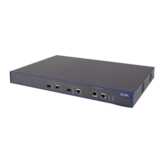
The models listed in this manual are not applicable to all regions. Please consult the local agents for the models applicable to your region. Product Overview WX5002 Access Controller H3C WX5002 Access Controller (AC), which are wholly developed by Hangzhou H3C Technologies Co., Ltd. -
Page 9: Front Panel
Front Panel Figure 1-2 Front panel of a WX5002 AC (1) Gigabit Ethernet interface 2—SFP optical interface (2) 1000 Mbps LED of gigabit Ethernet interface 2 (3) 10/100 Mbps LED of gigabit Ethernet interface 2 (4) 10/100/1000 Base-T auto-sensing Ethernet electrical interface 2 (5) Gigabit Ethernet interface 1—SFP optical interface (6) 1000 Mbps LED of gigabit Ethernet interface 1 (7) 10/100 Mbps LED of gigabit Ethernet interface 1... -
Page 10: Power Supply System
Power Supply System A WX5002 AC uses AC power supply, and provides two AC power sockets. The two AC power sockets can separately provide power supply for the WX5002 AC, or provide 1+1 redundancy backup for the AC to enhance the system reliability. AC input: Rated voltage range: 100 VAC to 240 VAC;... -
Page 11: System Specifications
Mark Status Description 1000 Mbps interface connection Solid green succeeds. The 1000 Mbps interface is receiving or 1000M Flashing green (6 Hz) transmitting data. The 1000 Mbps interface is not connected LED of gigabit or the connection fails. combo interface 10/100 Mbps interface connection Solid yellow succeeds. -
Page 12: Sfp Modules
Item Data Max power consumption (full load) 50 W Operating temperature 0°C to 45°C (32°F to 113°F) Relative humidity 10% to 90% (noncondensing) Either a gigabit SFP Ethernet optical interface or its corresponding 10/100/1000 BASE-T auto-sensing Ethernet electrical interface can be used at a time. SFP Modules A WX5002 AC provides two gigabit SFP Ethernet optical interfaces. -
Page 13: Installation Preparation
Installation Preparation Safety Precautions To avoid any device impairment and bodily injury caused by improper use, observe these rules: Pull the power plug(s) out of the AC before cleaning the AC. Do not clean the AC using wet cloth or liquid. -
Page 14: Requirements On Electromagnetic Susceptibility
Table 2-1 Dust concentration limit in the equipment room Physical active substance Concentration limit (particles/m Dust ≤ 3 × 10 (No visible dust on the tabletop over three days) Note: The dust particle diameter is ≥ 5 μm Besides the dust requirements, the AC equipment room also needs to strictly meet the requirements on the concentration of salt, acid, and sulfide. -
Page 15: Installation Tools
Installation Tools Flathead screwdriver Phillips screwdriver ESD-preventive wrist strap The installation tools are not provided with WX5002 AC. You need to prepare them yourself. -
Page 16: Installation
Installation When you ask your sales agent to maintain your AC, you must ensure that the dismantlement-preventive seal on a mounting screw of the AC chassis is intact. If you want to open the chassis, you should contact the agent for permission. Otherwise, you will bear any consequence resulting from your actions. -
Page 17: Installing A Ac On A Workbench
Installing a front mounting ear The following figures illustrate the installation of a front mounting ear: Figure 3-2 Install a front mounting ear onto a AC Figure 3-3 Install a front mounting ear onto a square-holed bracket Installing a AC on a Workbench In many cases, standard 19-inch racks are not available to users and ACs are often installed on clean workbenches. -
Page 18: Power Cords And Ground Wire Connection
Power Cords and Ground Wire Connection Connecting the AC Power Cord AC power socket (recommended) You are recommended to use a single-phase three-wire power socket with a neural point or a multifunction PC socket. The neutral point of the power in the building must be well grounded. Usually, the neutral points of power supplies in buildings are already grounded during cabling. -
Page 19: Connecting The Ground Wire
Connecting the Ground Wire Connect the AC ground wire properly since it is crucial to lightning protection and electromagnetic susceptibility (EMS). The power input end of the AC is connected with a noise filter, whose central ground is directly connected to the chassis, forming the chassis ground (also known as PGND). This chassis ground must be securely grounded so that induced and leaked electricity can be safely discharged to the ground, enhancing the EMS capability of the AC. -
Page 20: Console Cable Connection
Figure 3-6 Ground the AC by burying a grounding body into the earth (1) AC power socket (2) Grounding terminal (3) Protection ground wire (4) Earth (5) Angle steel For an AC-powered AC, if neither of the above-mentioned two conditions is available, ground the AC through a PE wire of the AC power supply. -
Page 21: Connecting The Console Cable
Figure 3-8 Console cable Table 3-1 Console cable pins and mapping relation RJ-45 Signal Direction DB9 (MODEM) DB9 (CONSOLE) → → → ← — ← ← ← Connecting the Console Cable Follow these steps to connect a terminal device, a PC for example, to the AC: Step 1: Plug the DB-9 female connector of the console cable to the serial interface of the PC or terminal where the AC is to be configured. -
Page 22: Gigabit Ethernet Interface Connection
Gigabit Ethernet Interface Connection A WX5002 AC provides two gigabit Ethernet combo interfaces on its front panel. The connection methods of the gigabit Ethernet electrical interface and the gigabit Ethernet optical interface are respectively described here. Connecting an Ethernet Electrical Interface Cables for connecting an Ethernet electrical interface Ethernet electrical interfaces usually use category 5 twisted pair cables, as shown in Figure 3-9. -
Page 23: Connecting An Ethernet Optical Interface
Step 2: View the LED of the Ethernet interface. ON means a link is present. OFF means no link is present. If the LED is OFF, check the line for the cause. Connecting an Ethernet Optical Interface Cables for connecting an Ethernet optical interface For 10/100/1000 Mbps Ethernet optical interfaces, use single-mode or multi-mode optical fibers to connect to the Ethernet based on the type of the installed 1000 Base-SX/LX SFP modules. - Page 24 All interface cables are routed indoors. If there are cables outdoors, check that a AC power strip with lightning protection and lightning arresters for network interfaces have been correctly connected.
-
Page 25: Initial Startup
Initial Startup Setting up the Configuration Environment Set up the configuration environment as shown below: Connect a terminal (a PC in this example) to the console interface on the AC with a console cable. Figure 4-1 Network diagram for initial startup Connecting the Console Cable Connect a console cable as follow: Step 1: Connect the DB-9 female connector of the console cable to the serial interface of the PC where... - Page 26 Figure 4-2 Connection description interface Type the name of the new connection in the connection description interface and click OK. The system displays the following interface. From the Connect using drop-down list, select the serial interface to be used. Figure 4-3 Set the serial interface used for HyperTerminal connection Click OK and the system displays the following interface.
- Page 27 Figure 4-4 Set serial interface parameters Click OK and the system displays the following interface. Figure 4-5 HyperTerminal window Set HyperTerminal properties. Select File > Properties > Settings in the HyperTerminal to enter the properties setting window, as shown in the following figure. Select the terminal emulation type as VT100 or Auto detect, and click OK to return to the HyperTerminal window.
-
Page 28: Powering On The
Figure 4-6 Set terminal emulation in H3C Properties window Powering On the AC Checking Before Power-On Before powering on the AC, verify that: The power cord is properly connected. The power supply voltage is within the range labeled on the AC. The console cable is properly connected;... - Page 29 Memory Speed : 140MHz BootWare Size : 512KB Flash Size : 32MB NVRAM Size : 512KB CPLD Version is 1.00 Hardware Version is Ver.B ......OK! ......OK! Press Ctrl+B to enter extend boot menu... The last line prompts you to enter the Boot menu. If you press <Ctrl + B>...
-
Page 30: Ac Software Maintenance
AC Software Maintenance Overview Files Managed by the AC BootWare program file The file is used to boot applications when the AC is started up. A complete BootWare program file includes two segments: basic and extended. Application file WX5002 AC support the Dual Image function. By default, the system defines three application files for booting: main, backup, and secure. -
Page 31: Ac Software Maintenance Methods
Configuration file The file stores configuration information of the AC. AC Software Maintenance Methods Upgrade BootWare and application programs using XMODEM protocol through a serial interface. Upgrading application programs from TFTP server through Ethernet interface in BootWare. Upload/download application programs and configuration files to/from the TFTP/FTP server through command lines. -
Page 32: Bootware Menu
BootWare Menu BootWare Main Menu When the AC is powered on and reboots, the following information is first displayed on the console terminal: System starts booting ... Then, the system prompts the following: ********************************************* H3C WCM BootWare , Ver 1.16 ******************************************* Copyright(c) 2004-2009 Hangzhou H3C Technologies Co., Ltd. -
Page 33: Bootware Submenus
You can try up to three times to type the BootWare password (the initial password is null). If you have tried three times but the password is still incorrect, you need to reboot the system. After you type the correct password, the system enters the BootWare main menu: ==================<EXTEND-BOOTWARE MENU>=================== | <1>... - Page 34 | <5> Modify Serial Interface Parameter | <0> Exit To Main Menu ============================================================= Enter your choice (0-5): Items in this submenu are described in the following table. Table 5-2 BootWare serial submenu Menu item Description <1> Download Application Program To SDRAM Download an application program to SDRAM And Run and run the program.
- Page 35 File control submenu Select 4 in the BootWare main menu to enter the file control submenu. You can view the application file types, modify file names, and delete files through the submenu. ========================<FILE CONTROL>======================= | <1> Display All File(s) | <2> Set Application File Type | <3>...
-
Page 36: Upgrading Bootware Through A Serial Interface
Upgrading BootWare Through a Serial Interface Use XMODEM to upgrade BootWare through a serial interface. Modifying Serial Interface Parameters Sometimes, we need to make the serial interface baud rate higher to save upgrading time or make it lower to guarantee transmission reliability. This section introduces how to adjust the serial interface baud rate. - Page 37 Figure 5-3 Modify the baud rate Select Call > Call to establish a new connection. Figure 5-4 Re-establish a call connection Then, press the Enter key, and the system will prompt the current baud rate and return to the previous menu.
-
Page 38: Upgrading Bootware
After you download files to SDRAM or upgrade application programs by changing the baud rate, restore the baud rate in the HyperTerminal to 9,600 bps in time, so as to ensure the normal display on the console screen when the system boots or reboots. Upgrading BootWare Enter the BootWare main menu and select 7 in the BootWare main menu (refer to section “BootWare Main Menu”... - Page 39 Figure 5-5 Send File dialog box Click Browse… to select the application program to be downloaded, and select Xmodem from the Protocol drop-down list. Then click Send and the following dialog box appears: Figure 5-6 Sending file dialog box After the BootWare program file is downloaded, the following information appears on terminal interface: Download successfully! 434432 bytes downloaded! Updating Basic BootWare ? Yes or No (Y/N):Y...
-
Page 40: Upgrading An Application Program Through A Serial Interface
The file name, size and path in the above figure may vary. Check the current BootWare and application program versions before upgrading. After you download a file to upgrade BootWare by changing the baud rate, restore the baud rate in the HyperTerminal to 9,600 bps in time, so as to ensure the normal display on the console screen when the system boots or reboots. -
Page 41: Upgrading An Application Program
One protocol for download, tftp. '.' = clear field; '-' = go to previous field; ^D = quit boot device : eth0 Boot device name. Cannot be changed. file name : wx5002.bin The download file name shall be consistentwith the real file name, and you need to designate the download path in TFTP settings. -
Page 42: Maintaining Application Programs And Configurations Through Command Lines
The TFTP server is not provided with H3C WX5002 AC. You need to purchase and install it yourself. Step 2: Modify Ethernet interface parameters. Refer to section “Configuring Ethernet Interface Parameters” on page 5-11 for details. Step 3: After the above configuration, select 3 in the BootWare main menu to enter the Ethernet submenu. -
Page 43: Maintaining The Ac Through The Tftp Server
Maintaining the AC Through the TFTP Server In the TFTP service, H3C WX5002 AC serve as TFTP clients, while the file server serves as the TFTP server. You can enter commands on the PC to upload or download configuration files and application programs of the AC to or from the file server. -
Page 44: Maintaining The Ac Through The Ftp Server
<H3C>tftp 192.168.0.1 get startup.cfg startup.cfg The file startup.cfg exists. Overwrite it?[Y/N]:y Verifying server file... Deleting the old file, please wait... File will be transferred in binary mode Downloading file from remote tftp server, please wait...\ TFTP: 1045 bytes received in 0 second(s) File downloaded successfully. - Page 45 Configure the IP addresses of the two sides on the same network. In this section, the IP address of the FTP client (PC) is set to 192.168.0.1, while that of the AC is set to 192.168.0.2. You can use the ping command on the PC or AC to check whether the connection is successful.
- Page 46 The following gives an example: <H3C>ftp 192.168.0.1 Trying 192.168.0.1 ... Press CTRL+K to abort Connected to 192.168.0.1. 220 3Com 3CDaemon FTP Server Version 2.0 User(192.168.0.1:(none)):guest Enter the username configured on the server 331 User name ok, need password Password: Enter the corresponding password 230 User logged in Connection succeeded.
-
Page 47: Maintaining Application And Configuration Files In Bootware
200 PORT command successful. 150 File status OK ; about to open data connection 226 Closing data connection; File transfer successful. FTP: 14323376 byte(s) sent in 15.974 second(s) 896.00Kbyte(s)/sec. [ftp]quit Quit FTP 221 Service closing control connection Maintaining Application and Configuration Files in BootWare You can modify and display a file type in the file control submenu: Select 4 in the BootWare main menu to enter the file control submenu. -
Page 48: Dealing With Password Loss
-Main +Backup -Backup Exit Enter your choice(1-5): You can set the file type to M (main) or B (backup) or cancel the setting by selecting 1 to 4. Refer to section “Application file” on page 5-1 for details. Deleting files Select 3 in the file control submenu to delete files: Delete File: **************************************************************************... -
Page 49: Bootware Password Loss
The system prompts the setting succeeds. Step 2: When the BootWare main menu appears again, select 0 to reboot the system. System starts booting ... Step 3: Set a new password in system view after reboot. [H3C]user-interface con 0 [H3C-ui-aux0]authentication-mode password [H3C-ui-aux0]set authentication password simple 123456 The above information indicates that the password authentication is adopted at the console interface and the password is set to 123456 and stored in plain text. -
Page 50: Super Password Loss
The password modification fails when the old password is incorrect or the new password is inconsistent, and the system will exit this operation. Super Password Loss The super password enables you to switch between four super levels. In the case of super password loss, you cannot perform higher level operations. -
Page 51: Maintenance And Troubleshooting
Maintenance and Troubleshooting Software Loading Failure If software loading fails, the system still runs the original version. In this case, check whether the physical interfaces are properly connected: If not, reconnect them correctly and restart the loading procedure. If so, view the loading information displayed on the HyperTerminal to check for input errors. If there is any input error, restart the loading procedure and ensure the input correctness. - Page 52 Bits per second: 9600 Data bits: 8 Parity: None Stop bits: 1 Flow control: None Emulation: VT100.
- Page 53 Table of Contents Appendix A Obtaining Support for your Product····················································································· A-1 Register Your Product···························································································································· A-1 Purchase Value-Added Services ··········································································································· A-1 Troubleshoot Online······························································································································· A-1 Access Software Downloads ················································································································· A-1 Telephone Technical Support and Repair ····························································································· A-1 Contact Us ············································································································································· A-2...
- Page 54 More information on 3Com maintenance and Professional Services is available at http://www.h3cnetworks.com. Contact your authorized reseller or 3Com for a complete list of the value-added services available in your area. Troubleshoot Online You will find support tools posted on the web site at http://www.h3cnetworks.com/ under Support,...
- Page 55 Details about recent configuration changes, if applicable To send a product directly to 3Com for repair, you must first obtain a return authorization number (RMA). Products sent to 3Com, without authorization numbers clearly marked on the outside of the package, will be returned to the sender unopened, at the sender’s expense.