
Related Manuals for Nintendo NES-001 - Entertainment System Game Console


Summary of Contents for Nintendo NES-001 - Entertainment System Game Console
- Page 1 Nintendo Entertainment System Documentation Version 1.0 August 2004 Patrick Diskin...
- Page 2 Preface Abstract The Nintendo Entertainment System (NES) was the world’s most widely used videogames console during the 1980s. From its initial release in 1983 until it was discontinued in 1995 the console brought gaming into more homes than ever before and paved the way for the videogame industry as it stands today.
- Page 3 Invaders, released in 1980. Bushnell disagreed with the direction Warner were taking and left the company in 1978. In 1979, Nintendo made their first attempt to break into the arcade game market but by 1981 their success had been limited. Hiroshi Yamauchi asked Nintendo graphic artist, Shigeru Miyamoto, to design a new game.
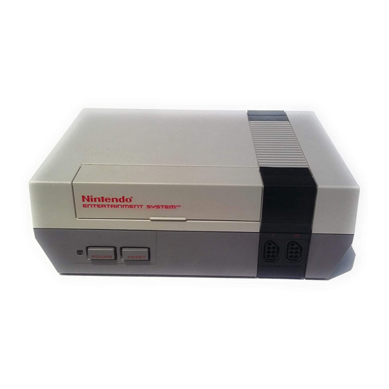
- Page 4 Figure 1-2. Redesigned NES released in 1993 [15]. In 1993, Nintendo released a redesigned version of the NES (as shown in figure 1-2) but the last NES game, Wario’s Woods was released in late 1994 and the system was officially discontinued in 1995 [16].
- Page 5 The games themselves often featured battery backed RAM to enable progress to be saved and Nintendo only predicted the battery life as five years. There are multiple options which allow the continued use of NES games and these are described here.
- Page 6 Static translation involves reading in the whole of the source program and translating it for the target system, producing a program that is executable on that system. However it is not always possible to determine how a program will execute from a static analysis of it.
- Page 7 Figure 1-4. The NES motherboard [27]. indicated. Nintendo designed the basic features required from the chips but found it difficult to find a company willing to produce such highly customised chips for the low price they were looking for. Ricoh agreed to manufacture the chips after Nintendo guaranteed them a three-million chip order.
- Page 8 can be transferred to a device via a write to a specific location in memory. Input devices are discussed in Part 5, the function of the memory mapped I/O is discussed throughout the document and specifically in Appendix B.
-
Page 9: Central Processing Unit
2 - Central Processing Unit 2.1 2A03 Overview Ricoh produced an NMOS processor based on the 6502, the 2A03. The chip differed from a standard 6502 in that it had the ability to handle sound, serving as pAPU (pseudo-Audio Processing Unit) as well as CPU, and that it lacked a Binary Coded Decimal (BCD) mode which allowed representing each digit using 4 bits. - Page 10 The 2A03 had a 16-bit address bus and as such could support 64 KB of memory with addresses from $0000-$FFFF. Figure 2-5 is the CPU memory map used by the NES, showing the layout of memory. The left hand map is a simplified version showing the major sections, while the map to the right divides these sections further.
- Page 11 Figure 2-3. CPU memory map. 2.3 Registers The 6502 has fewer registers than similar processors. There are three special purpose registers, the program counter, stack pointer and status register which each have a specific use. It also has three general purpose registers, the accumulator and the index registers, X and Y, which can be used to store data or control information temporarily.
- Page 12 The stack is located at memory locations $0100-$01FF. The stack pointer is an 8-bit register which serves as an offset from $0100. The stack works top-down, so when a byte is pushed on to the stack, the stack pointer is decremented and when a byte is pulled from the stack, the stack pointer is incremented.
- Page 13 Negative Flag (N) - Bit 7 of a byte represents the sign of that byte, with 0 being positive and 1 being negative. The negative flag (also known as the sign flag) is set if this sign bit is 1. The flags are arranged in the status register in the order shown in figure 2-3.
- Page 14 Figure 2-5. NMI (Non-Maskable Interrupt) handling. 2.5 Addressing Modes The 6502 has several different addressing modes, providing different ways to access memory locations. There are also addressing modes which operate on the contents of registers, rather than memory. In total there are 13 different addressing modes on the 6502. Some instructions can use more than one different addressing mode.
- Page 15 Jumps / Calls - Break sequential execution sequence, resuming from a specified address. Branches - Break sequential execution sequence, resuming from a specified address, if a condition is met. The condition involves examining a specific bit in the status register. Status Register Operations - Set or clear a flag in the status register.
- Page 16 3 - Picture Processing Unit 3.1 2C02 Overview Ricoh also supplied the 2C02 to serve as PPU. The PPU’s registers are mostly located in the I/O registers section of CPU memory at $2000-$2007 and $4014 as described in Appendix B. In addition, there are some special registers used for screen scrolling. 3.2 PPU Memory Map The PPU has its own memory, known as VRAM (Video RAM).
- Page 17 $10000 $10000 Mirrors Mirrors $0000-$3FFF $0000-$3FFF $4000 $4000 Mirrors $3F00-$3F1F Palettes $3F20 Sprite Palette $3F10 Image Palette $3F00 $3F00 Mirrors $2000-$2EFF $3000 Attribute Table 3 $2FC0 Name Table 3 $2C00 Attribute Table 2 Name Tables $2BC0 Name Table 2 $2800 Attribute Table 1 $27C0 Name Table 1...
- Page 18 only be written to. Bit 7 of £2000 can be used to disable NMIs. Remember that this type of interrupt is generated whenever a V-Blank occurs and is unaffected by the interrupt disable flag of the status register. Clearing this bit will prevent an NMI from occurring on V-Blank. Since the NES supports both 8x8 and 8x16 sprites, setting bit 5 of $2000 will switch to 8x16 sprites.
- Page 19 colours in each palette is 13, not 16 [5]. The total number of colours onscreen at any time is therefore 25 out of 52. Both palettes are also mirrored to $3F20-$3FFF. The colour palette is shown in Appendix F. 3.5 Pattern Tables The NES has two pattern tables at $0000 and $1000.
- Page 20 is 33221100 where every two bits specifies the most significant two colour bits for the specified square. Square 0 Square 1 Square 2 Square 3 Figure 3-3. 4x4 tile group layout. Adapted from [20]. The NES only has 2 KB to store name tables and attribute tables, allowing it to store two of each.
- Page 21 Single-screen mirroring points all four logical name tables to the same physical name table as shown in figure 3-6. Figure 3-6. Single-screen mirroring. Four-screen mirroring uses an additional 2 KB of RAM in the cartridge itself to allow logical name tables to each map to separate physical name tables as shown in figure 3-7. Figure 3-7.
- Page 22 A common technique used for scrolling involves determining whether sprite 0 is overlapping a non-transparent background pixel. If the system is drawing sprite 0, and any non- transparent pixel in it is in the same position as a non-transparent background pixel, the system sets the sprite 0 hit flag in bit 6 of $2002.
- Page 23 Some games only allow movement in one direction while others allow scrolling in both directions. This is described by Nintendo as follows [33]: “The PPU may display only 960 characters at a time, but it actually stores twice that amount.
- Page 24 It is clear that the status bar area of the screen is not scrolled in the same way as the rest and is fully resident on the first name table. This is typical of status information and is handled in Super Mario Bros. by using the sprite 0 hit flag and in Super Mario Bros. 3 by generating an IRQ.
- Page 25 3.9 Television Standards The NES connects to a television to display the game to user. As a result different versions of the system were created for the two television formats, NTSC and PAL. NTSC (National Television Standards Committee) is the standard used in North America, most of South America and parts of Asia [34].
- Page 26 Super Mario Bros. / Duck Hunt cartridge for the NES [28]. Figure shows difference between cartridges for the Famicom and NES. Nintendo designed a basic cartridge for the Famicom, as shown top in figure 4-1, but other developers designed their own cartridges with a variety of shapes, sizes and colours.
- Page 27 Figure 4-3. Cartridge inserted into NES [37]. Figure 4-4. Inside a NES cartridge [38]. 4.1.1 Memory Mappers The NES’ limited memory was sufficient for early games, however as they became more complex, games became larger and the memory was insufficient. To allow cartridges to contain more ROM, the NES had to be able to swap the data in and out of memory when it was needed.
- Page 28 The software that can be run using an emulator is usually referred to as a ROM image in reference to the original ROM chips used to store it. A simple dump of the contents of the cartridge is unlikely to be sufficient as it leaves no way to identify what each part of the file means.
- Page 29 2 million Disk Systems sold in 1986. However, the system was not popular with licensees who had to decide which format to release games for, and Nintendo’s strict licensing for Disk System games also made the format unpopular. When semiconductor prices dropped, cartridges could have a higher capacity than disks for the same price.
- Page 30 Figure 4-6. Mario Golf disk [41]. 4.3 Game Genie The Game Genie was a device that allowed gamers to cheat by adjusting the way the code is executed. The Game Genie was designed by Codemasters and distributed by Galoob Toys [14]. Other cheat devices worked by locking the value of a given memory location.
-
Page 31: Input Devices
1 to the port, followed by a 0. 5.2 Zapper When the NES first launched in America, Nintendo included a light-gun known as the Zapper. Figure 5-2 shows the original version of the Zapper, although the colour was later changed to orange. - Page 32 Figure 5-2. Original NES Zapper light-gun [45]. “The Zapper works by receiving the light from the screen. The contrast and brightness controls of the TV must be adjusted properly or the shots may not register. (The characters should be as bright as possible while the background areas should be as dark as possible.)”...
- Page 33 Appendix A Arithmetic And Logic A.1 Numbering Systems The hexadecimal number system uses base 16 with digits 0-9 and A-F, where A represents 10 and F represents 15. The hexadecimal system is used frequently throughout this document and any numbers written in this format will be indicated by use of the prefixes $ and 0x (used interchangeably).
- Page 34 Appendix B NES I/O Registers The following information is based on [7]: Address Access Level Description $2000 Write PPU Control Register 1: Bits 0-1 - Name table address, changes between the four name tables at $2000 (0), $2400 (1), $2800 (2) and $2C00 (3).
- Page 35 $2006 Write VRAM Address Register 2. $2007 Read / Write VRAM I/O Register: Reads or writes a byte from VRAM at the current address. $4000 Write pAPU Pulse 1 Control Register. $4001 Write pAPU Pulse 1 Ramp Control Register. $4002 Write pAPU Pulse 1 Fine Tune (FT) Register.
- Page 36 Appendix C iNES Mapper Numbers The following mapper numbers are based on [9]: iNES Mapper Number Mapper Name NROM, no mapper Nintendo MMC1 UNROM switch CNROM switch Nintendo MMC3 Nintendo MMC5 FFE F4xxx AOROM switch FFE F3xxx Nintendo MMC2 Nintendo MMC4...
- Page 37 Appendix D Memory Mapper Functions The information in this section is based on [6] with additional information about MMC1 from [46]. D.1 UNROM Switch Address Data $8000-$FFFF 16 KB PRG-ROM bank number to load into $8000. On reset, the first PRG-ROM bank is loaded into $8000 and the last PRG-ROM bank is loaded into $C000.
- Page 38 Bit 7 - Set to 1 to reset register. $C000-$DFFF Register 2: Bits 0-3 - VROM bank number to load into PPU $1000. If bit 4 of register 0 is set, this will be 4 KB banks n and (n + 1) where n is the value of bits 0-3, otherwise it is ignored.
-
Page 39: Appendix E 6502 Addressing Modes
Appendix E 6502 Addressing Modes E.1 Zero Page Zero page addressing uses a single operand which serves as a pointer to an address in zero page ($0000-$00FF) where the data to be operated on can be found. By using zero page addressing, only one byte is needed for the operand, so the instruction is shorter and, therefore, faster to execute than with addressing modes which take two operands. - Page 40 Figure E-2. Indexed zero page addressing. E.3 Absolute In absolute addressing, the address of the data to operate on is specified by the two operands supplied, least significant byte first. An example of an absolute instruction is AND $1234. Figure E-3. Absolute addressing.
- Page 41 E.4 Indexed Absolute Indexed absolute addressing takes two operands, forming a 16-bit address, least significant byte first, and adds the value of a register to it to give the address where the data can be found. For example, if the operands are bb and cc, the address of the data will be ccbb + X. There are two forms of indexed absolute addressing: Absolute, X - Add contents of X register to operand.
- Page 42 Figure E-5. Indirect addressing. E.6 Implied Many instructions do not require access to operands stored in memory. Examples of implied instructions are CLD (Clear Decimal Mode) and NOP (No Operation). E.7 Accumulator Some instructions operate directly on the contents of the accumulator. The only instructions to use this addressing mode are the shift instructions, ASL (Arithmetic Shift Left), LSR (Logical Shift Right), ROL (Rotate Left) and ROR (Rotate Right).
- Page 43 E.9 Relative Relative addressing is used in branch instructions. This addressing mode causes the value of the program counter to change if a certain condition is met. The condition is dependant on the instruction. The program counter increments by two regardless of the outcome of the condition but if the condition is true the single operand is added to the program counter to give the new value.
- Page 44 E.11 Indirect Indexed Indirect indexed (also known as post-indexed) addressing takes a single operand which gives the zero page address of the least significant byte of a 16-bit address which is then added to the Y register to give the target address. For example, if the operand is bb, 00bb is xx and 00bb + 1 is yy, then the data can be found at yyxx.
- Page 45 Appendix F NES Colour Palette There are different interpretations of the NES colour palette. The palette as defined in [47] is shown below. Alternatives are presented in [5] and [48]. Figure F-1. NES colour palette. Palette RGB Value Palette RGB Value Entry Entry 75, 75, 75...
- Page 46 Computer Science, University of Maryland, http://fms.komkon.org/EMUL8/NES.html (link no longer works, a copy of version 2.2 is at http://oldnes.sourceforge.net/doc/NES- %20by%20Marat%20Fayzullin.html), 2002 [10] David Sheff, Game Over: Nintendo’s Battle To Dominate An Industry, Hodder and Stoughton, 1993 [11] Nintendo, “Company History”, Nintendo of America Inc., http://www.nintendo.com/corp/history.jsp, 2004...
- Page 47 [27] Marcus Liedholm and Mattias Liedholm, “Nintendo Entertainment System (NES) or Famicom Tech specs and Hardware”, Nintendo Land, http://www.nintendoland.com/home2.htm?nes/tech.htm, 2000 [28] Christian Nutt and Benjamin Turner, “Nintendo Famicom: 20 Years Of Fun”, GameSpy, http://archive.gamespy.com/articles/july03/famicom/index.shtml, 2003 [29] Lance A. Leventhal, 6502 Assembly Language Programming (Second Edition), McGraw-Hill, 1986 [30] Alan Clements, The Principles of Computer Hardware (Second Edition), pp.