Advertisement
Quick Links
DeviceNet Communication Module (CME-DN01) Instruction Sheet
DeviceNet is a trademark of the Open DeviceNet Vendor Association, Inc
Please thoroughly read and understand the following contents to ensure correct use before operation.
The content of this instruction sheet may be revised without prior notice. Please consult our distributors or
download the most updated version at http://www.delta.com.tw/industrialautomation
A.
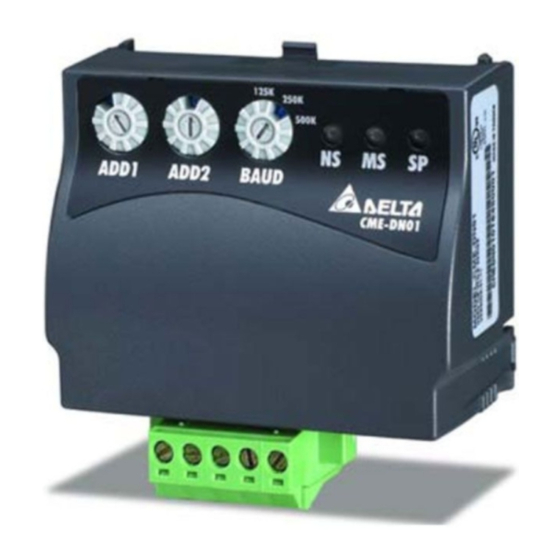
Panel Appearance and Dimensions
3
4
5
125K
250K
500K
NET
M OD
SP
ADD1 ADD2
BAUD
CME-DN01
2
72.2 [2.84]
1. For RS-485 connection to VFD-E
2. Communication port for connecting DeviceNet network
3. Address selector
4. Baud rate selector
5. Three LED status indicators for monitor
B.
Wiring and Settings
Refer to following diagram for details.
MAC address Date Rate
125K
250K
500K
NET
MOD
SP
ADD1 ADD2
BAUD
CME-DN01
Setting baud rate
0
BAUD
Switch
Baud
Value
Rate
0
125K
1
250K
2
500K
NOT
Other
used
C.
Mounting Method
Step1 and step2 show how to mount this communication
module onto VFD-E. The dimension in the following is for
your reference.
1
35.8 [1.41]
3.5 [0.14]
UNIT: mm(inch)
1: Reserved
2: EV
3: GND
4: SG-
5: SG+
6: Reserved
7: Reserved
8: Reserved
Empty
V+
CAN-H
CAN-L
V-
pin
Setting MAC addresses:
use decimal system.
ADD1
ADD2
.
Dimensions
STEP 1
D.
Power Supply
No external power is needed. Power is supplied via
RS-485 port that is connected to VFD-E. An 8 pins RJ-45
cable, which is packed together with this communication
module, is used to connect the RS-485 port between
VFD-E and this communication module for power. This
communication module will perform the function once it is
connected. Refer to the following paragraph for LED
indications.
E.
LEDs Display
1. SP: Green LED means in normal condition, Red LED
means abnormal condition.
2. Module: Green blinking LED means no I/O data
transmission, Green steady LED means I/O data
transmission OK. Red LED blinking or steady LED
means module communication is abnormal.
3. Network: Green LED means DeviceNet
communication is normal, Red LED means abnormal.
NOTE
Please download the auto EDS generator and user manual
at http://www.delta.com.tw/industrialautomation/
2007-10-12
5011642701-DNT1
UNIT: mm(inch)
STEP 2
Advertisement

Related Manuals for Delta Electronics DeviceNet CME-DN01


Summary of Contents for Delta Electronics DeviceNet CME-DN01
- Page 1 DeviceNet Communication Module (CME-DN01) Instruction Sheet DeviceNet is a trademark of the Open DeviceNet Vendor Association, Inc Please thoroughly read and understand the following contents to ensure correct use before operation. The content of this instruction sheet may be revised without prior notice. Please consult our distributors or download the most updated version at http://www.delta.com.tw/industrialautomation Panel Appearance and Dimensions 125K...
- Page 2 DeviceNet 通訊模組(CME-DN01)說明書 DeviceNet 是 ODVA(Open Device Vendor Association) 的註冊商標。 請詳細閱讀下列說明後才使用本產品,以確保使用安全。 由於產品精益求精,當內容規格有所修正時,請洽詢代理商或至台達網站 (http://www.delta.com.tw/ch/product/em/em_main.asp)下載最新版本。 A. 面板尺寸外觀 125K 250K 500K NE T M OD AD D1 ADD2 B AUD CME-DN01 72.2 [2.84] 35.8 [1.41] 1. 與 VFD-E 系列連接的 RS-485 通訊接口 2. 連接 DeviceNet 通訊網路接口 3.