Table of Contents
Advertisement
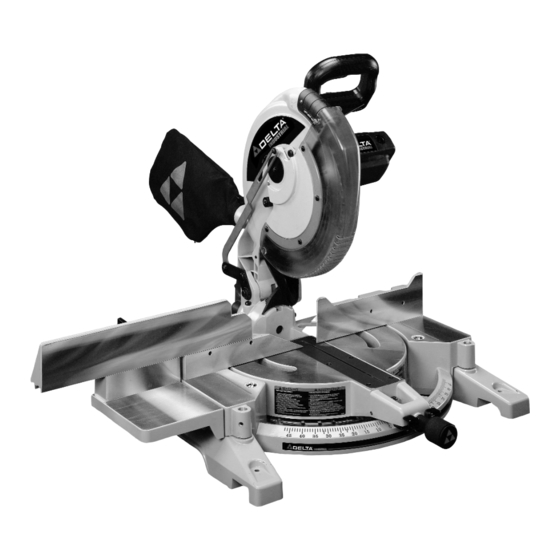
12" Compound Laser Miter Saw
(Model 36-255L)
™
PART NO. A05727 - 04-21-05
Copyright © 2005 Delta Machinery
To learn more about DELTA MACHINERY
ESPAÑOL: PÁGINA 25
visit our website at: www.deltamachinery.com.
For Parts, Service, Warranty or other Assistance,
1-800-223-7278 (
1-800-463-3582).
please call
In Canada call
Advertisement
Table of Contents

Related Manuals for Delta TwinLaser 36-255L


Summary of Contents for Delta TwinLaser 36-255L
- Page 1 12" Compound Laser Miter Saw (Model 36-255L) ™ PART NO. A05727 - 04-21-05 Copyright © 2005 Delta Machinery To learn more about DELTA MACHINERY ESPAÑOL: PÁGINA 25 visit our website at: www.deltamachinery.com. For Parts, Service, Warranty or other Assistance, 1-800-223-7278 ( 1-800-463-3582).
-
Page 2: Table Of Contents
NOT be modified and/or used for any application other than for which it was designed. If you have any questions relative to its application DO NOT use the product until you have written Delta Machinery and we have advised you. -
Page 3: Safety Guidelines
SAFETY GUIDELINES - DEFINITIONS It is important for you to read and understand this manual. The information it contains relates to protecting YOUR SAFETY and PREVENTING PROBLEMS. The symbols below are used to help you recognize this information. Indicates an imminently hazardous situation which, if not avoided, will result in death or serious injury. Indicates a potentially hazardous situation which, if not avoided, could result in death or serious injury. -
Page 4: General Safety Rules
Damage to the machine and/or injury may result. 13. USE RECOMMENDED ACCESSORIES. The use of accessories and attachments not recommended by Delta may cause damage to the machine or injury to the user. IMPORTANT SAFETY INSTRUCTIONS 14. USE THE PROPER EXTENSION CORD. Make sure your extension cord is in good condition. -
Page 5: Additional Specific Safety Rules
15. NEVER START THE TOOL with the workpiece against the blade. 16. KEEP HANDS out of path of saw blade. Clamp all workpieces that would require your hand to be in the “Table Hazard Zone” (within the red lines). -
Page 6: Power Connections
POWER CONNECTIONS A separate electrical circuit should be used for your machines. This circuit should not be less than #12 wire and should be protected with a 20 Amp time lag fuse. If an extension cord is used, use only 3-wire extension cords which have 3- prong grounding type plugs and matching receptacle which will accept the machine’s plug. -
Page 7: Functional Description
FUNCTIONAL DESCRIPTION FOREWORD Delta Model 36-255L is a high capacity 12" compound laser miter saw designed to cut wood and non-ferrous metals. This unit incorporates the latest technology TwinLaser™, line-of-cut indicator feature. It can crosscut 8" x 2¼" and 7" x 3¼", miter at 45°... -
Page 8: Carton Contents
TO THE 0° CUT-OFF POSITION” in this manual (Fig. 5 & 7). 5. Unassembled items are shown in Fig. 3 for identification and use in assembling the saw. ASSEMBLY TOOLS REQUIRED " arbor and fence wrench (supplied) * 1/4” hex wrench (supplied) * Open end 7/16 wrench (supplied) * 1/8”... - Page 9 NOTE: Turn the screws only a few threads into the holes at this time. 2. Attach the table extension (B) Figs. 7A and 7B, to left side of saw table, making sure groove of table extension (B) is inside flat washers (C) as shown in Fig. 7B.
- Page 10 NOTE: Do not completely tighten screws at this time. 5. Use a straight edge (C) Fig. 7E, to align the fence slide support (E) with saw fence (J), and tighten the two screws. 6. Position the fence slide (K) Fig. 7F, in position on top of saw fence (J) and fence slide support (E).
-
Page 11: Operations
Before operating your compound miter saw, firmly mount it to a workbench or other supporting surface. Four holes, (A) Fig. 9, are provided for fastening the saw to a supporting surface. When frequently moving the saw from place to place, mount the saw to a 3/4”... - Page 12 ROTATING THE TABLE FOR MITER SAW CUTTING 1. The compound miter saw will cut any angle from a straight 0 cut to 47 right and left. Turn locking knob ° ° (A) Fig. 12 counterclockwise, depress lock lever (B), and rotate table to desired position.
- Page 13 ADJUSTING FENCE 90° TO BLADE IMPORTANT: BEFORE MAKING THIS ADJUSTMENT, SET THE BLADE AT 0° TO THE TABLE. SEE SECTION “ADJUSTING 0° AND 45° BEVEL POSITIVE STOPS.” DISCONNECT THE MACHINE FROM THE POWER SOURCE. 2. Rotate the movable table so that the blade is 90° to the fence and the positive stop is set for 0°.
-
Page 14: Tilting Cuttinghead For Bevel Cutting
(A). 3. Positive stops are provided to rapidly position the saw blade at 90° and 45° to the table. Refer to the section of this manual titled “ADJUSTING 90° AND 45° BEVEL POSITIVE STOPS.” The bevel angle of the cutting arm is determined by the position of the pointer (C) Fig. -
Page 15: Adjusting Chip Deflector
STOPS DISCONNECT THE MACHINE FROM THE POWER SOURCE. 2. Adjust saw so that both bevel and miter pointers are set at 0°. Tighten bevel lock handle and lock cuttinghead in down position. 3. Place one end of a square (A) Fig. 23 on the table and the other end against the blade. -
Page 16: Adjusting Sliding Fit Between Trunnion And Bevel Bracket
Correct adjustment is a good snug sliding fit between these two parts. This adjustment should not be so tight that it restricts the sliding movement of the cuttinghead arm (B) or so loose that it affects the accuracy of the saw cut. ADJUSTING DOWNWARD TRAVEL OF... - Page 17 LASER USE AND ADJUSTMENTS The TwinLaser™ laser units are mounted in a housing that is fitted into the upper blade guard of the miter saw (Fig. A). The lasers project a beam of light downward, along both sides and parallel to the saw blade. This beam of light produces a line- of-cut indicator (a red outline of where the saw blade will cut) on the workpiece.
- Page 18 Fig. J. Do not use solvents of any kind since they may damage the lens. Avoid touching sharp points of saw blade with your hands or fingers. Dust build-up can block the laser and prevent it from accurately indicating the line of cut.
-
Page 19: Typical Operations And Helpful Hints
1. Before cutting, make certain the cutting arm and table area are at their correct settings and firmly locked in place. 2. Before cutting, determine that the workpiece is the right size for the saw. 3. Place the workpiece on the table and hold or clamp it firmly against the fence. - Page 20 NOTE: Ensure that the top of the support 2 x 4’s (C) are level with the miter saw table. This is critical because the distance from the top of the 2 x 4’s (A) to the miter saw table varies from saw to saw. In most cases, standard 2 x 4’s (C) can used.
-
Page 21: Cutting Crown Moulding
CUTTING CROWN MOULDING One of the many features of the saw is the ease of cutting crown moulding. The following is an example of cutting both inside and outside corners on 52°/38° wall angle crown moulding. 1. Move the table to the 31.62° right miter position and lock the table in position. NOTE: A positive stop is provided to find this angle quickly. -
Page 22: Troubleshooting
For assistance with your machine, visit our website at www.deltamachinery.com for a list of service centers or call the DELTA Machinery help line at 1-800-223-7278 (In Canada call 1-800-463-3582). CHANGING THE BLADE USE ONLY CROSS-CUTTING SAW BLADES. DO NOT USE BLADES WITH DEEP... -
Page 23: Service
Two Year Limited New Product Warranty Delta will repair or replace, at its expense and at its option, any new Delta machine, machine part, or machine accessory which in normal use has proven to be defective in workmanship or material, provided that the customer returns the product prepaid to a Delta factory service center or authorized service station with proof of purchase of the product within two years and provides Delta with reasonable opportunity to verify the alleged defect by inspection. - Page 24 NOTES...
-
Page 25: Español
Phone: (604) 420-0102 Fax: (604) 420-3522 The following are trademarks of PORTER-CABLE • DELTA (Las siguientes son marcas registradas de PORTER-CABLE • DELTA S.A.) (Les marques suivantes sont des marques de fabriquant de la PORTER-CABLE • DELTA): Auto-Set Contractor’s Saw II™, Delta ®...