
Related Manuals for Gigabyte GA-2CEWH


Summary of Contents for Gigabyte GA-2CEWH
- Page 1 GA-2CEWH AMD Socket 940 Dual Processor Motherboard USER’S MANUAL AMD Opteron Socket 940 Dual Processor Motherboard ™ Rev. 1003...
-
Page 2: Table Of Contents
Item Checklist ..................4 WARNING! ....................4 Chapter 1 Introduction ................5 Summary of Features .................. 5 GA-2CEWH Motherboard Layout ..............7 Chapter 2 Hardware Installation Process ..........9 Step 1: Installing Processor and CPU Cooling Fan........10 Step1-1: Installing CPU ....................10 Step1-2: Installing Cooling Fan .................. - Page 3 Table of Content I/O Device Configuration ....................56 PCI Configuration ......................58 Security ...................... 61 Power ......................64 Boot ......................66 Boot Device Priority ......................68 Exit ......................69 Chapter 4 Technical Reference ............72 Block Diagram ................... 72 Chapter 5 Application Driver Installation ..........73 A.NVDIA Chipset Driver Installation ................
-
Page 4: Item Checklist
GA-2CEWH Motherboard Item Checklist The GA-2CEWH motherboard I/O shield x 1 SATA Cable x 4 FDD Cable x 1 CD for motherboard driver & utility GA-2CEWH user’s manual WARNING! Computer motherboards and expansion cards contain very delicate Integrated Circuit (IC) chips. To protect them against damage from static electricity, you should follow some precautions whenever you work on your computer. -
Page 5: Chapter 1 Introduction
Form Factor 30.4cm x 33.0cm EATX size form factor, 8 layers PCB. Motherboard GA-2CEWH Motherboard Support Dual Opteron processors (Sledge Hammer) The HyperTransport link of the AMD Opteron processor is capable of operating at 400, 800, 1200, and 1600 MT/s. - Page 6 GA-2CEWH Motherboard On-Board Peripherals 1 Floppy port supports 2 FDD with 360K, 720K,1.2M, 1.44M and 2.88M bytes. 1 Parallel port supports Normal/EPP/ECP mode 1 Serial port (COM) 8 x USB 2.0 2 x RJ45 LAN port 2 x IEEE 1394a...
-
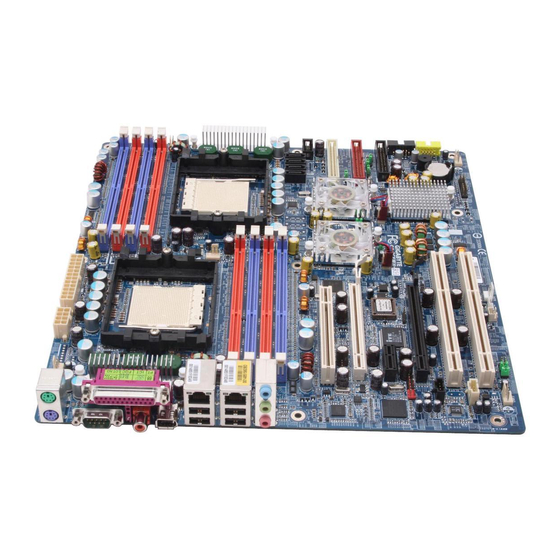
Page 7: Ga-2Cewh Motherboard Layout
Introduction GA-2CEWH Motherboard Layout 21 22 19 20 11 12... - Page 8 GA-2CEWH Motherboard CPU0 SPDIF_IO_IN_OUT CPU1 CENTER_SOUOUND NVIDIA nForce Profession 20503. FAN1 (CPU0 Fan) NVIDIA nForce Profession 22204. FAN5 (CPU1 Fan) AMD8132 FAN4 (Front Fan) Broadcom BCM5751T FAN3 (Rear Fan) ITE IT8712F-A FAN2 (System Fan) BIOS IO4_FAN IDE1 CK-804_FAN IDE2 SLOT1...
-
Page 9: Chapter 2 Hardware Installation Process
Hardware Installation Process Chapter 2 Hardware Installation Process To set up your computer, you must complete the following steps: Step 1- Install the Central Processing Unit (CPU) Step 2- Install memory modules Step 3- Install expansion cards Step 4- Connect ribbon cables, cabinet wires, and power supply Step 5- Setup BIOS software Step 6- Install supporting software tools Step 3... -
Page 10: Step 1: Installing Processor And Cpu Cooling Fan
GA-2CEWH Motherboard Step 1: Installing Processor and CPU Cooling Fan Before installing the processor and cooling fan, adhere to the following cautions: 1. The processor will overheat without the heatsink and/or fan, resulting in permanent irreparable damage. 2. Never force the processor into the socket. - Page 11 Hardware Installation Process Figure 3. A1 pin location on the Socket and Processor.Move the socket lever to the locked position while holding pressure on the center of the processor. Step 4. When the processor installation is completed, apply thermal grease to the processor(as shown in Figure 4) prior to installing the heatsink.
-
Page 12: Step1-2: Installing Cooling Fan
GA-2CEWH Motherboard Step1-2: Installing Cooling Fan Step 1. Attach th cooling fan clip to the processor scoket. Align the heatsink assembly with the support frame mating with the backer plate standoffs as shown in Figure 5&6. Step 2. Coonect the processor fan cable to the processor fan connector. -
Page 13: Step 2: Install Memory Modules
Hardware Installation Process Step 2: Install memory modules Before installing the processor and heatsink, adhere to the following warning: Please note that the DIMM module can only fit in one direction due to the one notches. Wrong orientation will cause improper installation. Please change the insert orientation. The motherboard has 8 dual inline memory module (DIMM) sockets. -
Page 14: Installation Step
GA-2CEWH Motherboard Total Memory Sizes With Registered DDR DIMM Devices used on DIMM 1 DIMMx64/x72 2 DIMMsx64/x72 3 DIMMsx64/x72 4 DIMMsx64/x72 64 Mbit (4Mx4x4 banks) 256 MBytes 512 MBytes 768 MBytes 1 GBytes 64 Mbit (2Mx8x4 banks) 128 MBytes 256 MBytes... - Page 15 Hardware Installation Process Table 1. Vaild DIMM Configuration for 64 bit Mode DIMM 0 (MB) DIMM 2 (MB) 1024 1024 1024 2048 2048 2048 4096 4096 4096 Note: X = Do not populate Table 2. Vaild DIMM Configuration for 128 bit Mode Logical DIMM 0 Ligical DIMM1 DIMM 0 (MB)
-
Page 16: Step 3: Install Expansion Cards
GA-2CEWH Motherboard Step 3: Install expansion cards 1. Read the related expansion card’s instruction document before install the expansion card into the computer. 2. Remove your computer’s chassis cover, screws and slot bracket from the computer. 3. Press the expansion card firmly into expansion slot in motherboard. -
Page 17: Step 4: Connect Ribbon Cables, Cabinet Wires, And Power Supply
Hardware Installation Process Step 4: Connect ribbon cables, cabinet wires, and power supply Step4-1:I/O Back Panel Introduction... - Page 18 GA-2CEWH Motherboard PS/2 Keyboard and PS/2 Mouse Connector To install a PS/2 port keyboard and mouse, plug the mouse to the upper port (green) and the keyboard to the lower port (purple). Parallel Port / Serial Port This connector supports 1 standard COM port and 1 Parallel port. Device like printer can be connected to Parallel port ;...
- Page 19 Hardware Installation Process Audio Connectors After install onboard audio driver, you may connect speaker to Line Out jack, micro phone to MIC In Line Out jack. (Front Speaker) Device like CD-ROM , walkman etc can be Line In connected to Line-In jack. Please note: (Rear Speaker) MIC In...
-
Page 20: Step4-2: Connectors Introduction
GA-2CEWH Motherboard Step4-2: Connectors Introduction... - Page 21 Connector Introduction A) AXT2 R) AUX_IN B) ATX1 S) CD_IN1 C) IDE1 T) SPDIF_IO D) IDE2 U) SUR_CEN1 E) FDD V) BT F) F_USB2 W) FAN1 G) F_USB1 X) FAN5 H) SATA0 Y) IO4_FAN I) SATA1 Z) CK804_FAN J) SATA2 1) FAN2 K) SATA3 2) FAN4...
- Page 22 GA-2CEWH Motherboard A ) ATX2 PIN No. Definition +3.3V +3.3V 5VSB +12V +12V +3.3V +3.3V -12V PSON AC power cord should only be connected to your power supply unit after ATX power cable and other related devices are firmly connected to the mainboard.
- Page 23 Connector Introduction C / D ) IDE 1/2 Please connect first harddisk to IDE1 and connect CDROM to IDE2. The red stripe of the ribbon cable must be the same side with the Pin1. E ) FDD1 (Floppy Connector) Please connect the floppy drive ribbon cables to FDD. It supports 360K,720K,1.2M,1.44M and 2.88Mbytes floppy disk types.
- Page 24 GA-2CEWH Motherboard F ) F_ USB2 (Front USB Connector) PIN No. Definition Do Not Connect Do Not Connect Power Power Data- Data- Data+ Data+ G ) F_ USB1 (Front USB Connector) PIN No. Definition Power Power Data- Data- Data+ Data+ Be careful with the polarity of the front panel USB connector.
- Page 25 Connector Introduction H / I / J / K ) SATA0/1/2/3 (Serial ATA Connector) SATA0~3 Pin No. Definition SATA0~3 L ) CI (CASE OPEN) This 3 pin connector allows your system to enable or disable the “case open” item in BIOS if the system case begin remove.
- Page 26 GA-2CEWH Motherboard M ) F_Panel1 (2X10 Pins) Please connect the power LED, PC speaker, reset switch and power switch etc of your chassis front panel to the front panel jumper according to the pin assignment below. IDE Hard Disk Power Sleep LED...
- Page 27 Connector Introduction N ) WOL (Wake On LAN Connector) This connector allows the remove servers to manage the system that installed this mainboard via your network adapter which also supports WOL. Pin No. Definition +5V SB Signal O ) WOR (Wake on Ring Connector) Pin No.
- Page 28 GA-2CEWH Motherboard P ) F_Audio (Front Audio connector) If you want to use Front Audio connector, you must remove 5-6, 9-10 Jumper. In order to utilize the front audio header, your chassis must have front audio connector. Also please make sure the pin assigment on the cable is the same as the pin assigment on the MB header.
- Page 29 Connector Introduction R ) AUX_IN ( AUX In Connector) Connect other device(such as PCI TV Tunner audio out)to the connector. Pin No. Definition AUX-L AUX-R S ) CD_IN (CD IN,Black) Connect CD-ROM or DVD-ROM audio out to the connector. Pin No. Definition CD-L CD_R...
- Page 30 GA-2CEWH Motherboard T )SPDIF_IO (Red Connector) The SPDIF output is capable of providing digital audio to external speakers or compressed AC3 data to an external Dolby Digital Decoder. Use this feature only when your stereo system has digital input function.
- Page 31 Connector Introduction V ) BT (Battery) CAUTION Danger of explosion if battery is incorrectly replaced. Replace only with the same or equivalent type recommended by the manufacturer. Dispose of used batteries according to the manufacturer’s instructions. If you want to erase CMOS... 1.Turn OFF the computer and unplug the power cord.
- Page 32 GA-2CEWH Motherboard Y ) IO4_FAN (NVIDIA IO-4 Chipset FAN connector) If you installed wrong direction, the Chip Fan will not work. Sometimes will damage the Chip Fan. Pin No. Definition Sense Z ) CK804_FAN (NVIDIA CK804 Chipset FAN connector) If you installed wrong direction, the Chip Fan will not work. Sometimes will damage the Chip Fan.
- Page 33 Connector Introduction 1 / 2 / 3 ) FAN2 / 4 / 3 (Front Fan / Rear Fam / System FAN) This connector allows you to link with the cooling fan on the system case to lower the system temperature. FAN4 FAN2 Pin No.
- Page 34 GA-2CEWH Motherboard 5 ) CLR_CMOS1 (Clear CMOS Function) You may clear the CMOS data to its default values by this jumper. Default value doesn’t include the “Shunter” to prevent from improper use this jumper. To clear CMOS, temporarily short 1-2 pin.
-
Page 35: Chapter 3 Bios Setup
BIOS Setup Chapter 3 BIOS Setup BIOS Setup is an overview of the BIOS Setup Program. The program that allows users to modify the basic system configuration. This type of information is stored in battery-backed CMOS RAM so that it retains the Setup information when the power is turned off. -
Page 36: Getting Help
GA-2CEWH Motherboard GETTING HELP Main Menu The on-line description of the highlighted setup function is displayed at the bottom of the screen. Status Page Setup Menu / Option Page Setup Menu Press F1 to pop up a small help window that describes the appropriate keys to use and the possible selections for the highlighted item. -
Page 37: Main
BIOS Setup Main Once you enter Phoenix BIOS Setup Utility, the Main Menu (Figure 1) will appear on the screen. Use arrow keys to select among the items and press <Enter> to accept or enter the sub-menu. Phoenix TrustedCore(tm) Setup Utility Main Advanced Security... - Page 38 GA-2CEWH Motherboard Diskette A This category identifies the type of floppy disk drive A that has been installed in the computer. Disabled Disable this device. 360KB inch AT-type high-density drive; 360K byte capacity 1.2MB inch AT-type high-density drive; 1.2M byte capacity 720K inch double-sided drive;...
- Page 39 BIOS Setup Multi-Sector Transfer This field displays the information of Multi-Sector Transfer Mode. Disabled: The data transfer from and to the device occurs one sector at a time. Auto: The data transfer from and to the device occurs multiple sectors at a time if the device supports it.
-
Page 40: System Information
GA-2CEWH Motherboard System Information This category includes the information of BIOS Version, BIOS Date,and MAC address. System Memory The POST of the BIOS will determine the amount of base (or conventional) memory installed in the system. The value of the base memory is typically 512K for systems with 512K memory installed on the motherboard, or 640 K for sy stems with 640K or more memory installed on the motherboard. -
Page 41: Advanced
BIOS Setup Advanced Phoenix TrustedCore(tm) Setup Utility Main Advanced Security Power Boot Exit Hardware Monitoring Item Specific Help BIOS Event Logging Processor Hammer Configuration Chipset Diskette Controller ATA Controller Integrated Network Interface Integrated Audio Integrated USB Integrated 1394 I/O Device Configuration PCI Configuration Reset Configuration [No]... -
Page 42: Hardware Monitoring
GA-2CEWH Motherboard Hardware Monitoring PhoenixTrustedCore(tm) Setup Utility Advanced Hardware Monitoring Item Specific Help Realtime Sensors: F1: Help : Select Item + -: Change Values F5: Setup Defaults Esc: Exit : Select Menu Enter: Select Sub-Menu F10: Save&Exit Figure 2-1: Hardware Monitoring Realtime Sensors This category displays system health information and voltage detection. -
Page 43: Bios Event Logging
BIOS Setup BIOS Event Logging PhoenixTrustedCore(tm) Setup Utility Advanced BIOS Event Logging Item Specific Help BIOS Event Logging [Enabled] View DMI External Log [Enter] Clear BIOS event logging [Disabled] F1: Help : Select Item + -: Change Values F5: Setup Defaults Esc: Exit : Select Menu Enter: Select... -
Page 44: Processor
GA-2CEWH Motherboard Processor PhoenixTrustedCore(tm) Setup Utility Advanced Processor Item Specific Help CPU0 Type: AMD Optern(tm) Processor 244 CPU0 Speed: 1800Mz CPU0 ID: 0751 CPU0 Patch ID: 004D MPS Version: [1.4] F1: Help : Select Item + -: Change Values F5: Setup Defaults... -
Page 45: Hammer Configuration
BIOS Setup Hammer Configuration PhoenixTrustedCore(tm) Setup Utility Advanced Hammer Configuration Item Specific Help HT-LDT Frequency: [100MHz] MTRR Mapping Methods: [Continuous] Memhole mapping [Hardware] ECC: [Enabled] ECC Scrub Redirection [Enabled] 4-bit ECC: [Disabled] DCAHE ECC Scrub CTL: [Disabled] L2 ECC Scrub CTL: [Disabled] Dram ECC Scrub CTL: [Disabled]... - Page 46 GA-2CEWH Motherboard MTRR Mapping Method Select the CPU Memory Type Range Register (MTRR) mapping method. Continuous Default method. (Default value) Dicrete Compatible with Linux AGP. Memhole mapping Remapping scheme of PCI memory hole. Hardware Select Hardware as the PCI memory hole. (Default value) Software Select Software as the PCI memory hole.
- Page 47 BIOS Setup DCACHE ECC Scrub CTL This option allows user to set the rates of background scrubbing for DCACHE lines. Set the rates of background scrubbing for DCACHE lines. Enabled Disabled Disable this function. (Default value) L2 ECC Scrub CTL This option allows user to set the rates of background scrubbing for L2 cache lines.
-
Page 48: Chipset
GA-2CEWH Motherboard Chipset PhoenixTrustedCore(tm) Setup Utility Advanced Chipset Item Specific Help DRAM Bank Interleaving [Auto] NODE memory Interleaving [Auto] ACPI SRAT Table [Disabled] ECC Memory Checking [Enabled] F1: Help : Select Item + -: Change Values F5: Setup Defaults Esc: Exit... -
Page 49: Diskette Controller
BIOS Setup Diskette Controller PhoenixTrustedCore(tm) Setup Utility Advanced Diskette Controller Item Specific Help Diskette Controller [Enabled] F1: Help : Select Item + -: Change Values F5: Setup Defaults Esc: Exit : Select Menu Enter: Select Sub-Menu F10: Save&Exit Figure 2-6: Diskette Controller Diskette Controller Auto BIOS will automatically start configuration for floppy diskette controller. -
Page 50: Ata Controller
GA-2CEWH Motherboard ATA Controller PhoenixTrustedCore(tm) Setup Utility Advanced ATA Controller Item Specific Help P-ATA Interface [Pata 1/2 + P-ATA 3/4] S-ATA Interface [Enabled] S-ATA Mode [Native] F1: Help : Select Item + -: Change Values F5: Setup Defaults Esc: Exit... -
Page 51: Integrated Network Interface
BIOS Setup Integrated Network Interface PhoenixTrustedCore(tm) Setup Utility Advanced Integrated Network Interface Item Specific Help Integrated Network Interface 1 (Broadcom) Integrated Network Interface 2 (NVDIA) F1: Help : Select Item + -: Change Values F5: Setup Defaults Esc: Exit : Select Menu Enter: Select Sub-Menu F10: Save&Exit... - Page 52 GA-2CEWH Motherboard Integrated Network Interface 2 (NVDIA) Integrated Network Interface Enabled Enable onboard LAN (NVDIA) controller. (Default value) Disabled Disable this function. Latency Timer Default Minimum guaranteed time slice allotted for bus master units of PCI bus clocks. (Defualt value) Options 0020h, 0040h, 0060h, 0080h, 00A0h, 00C0h, 00Eh.
-
Page 53: Integrated Audio
BIOS Setup Integrated Audio PhoenixTrustedCore(tm) Setup Utility Advanced Integrated Audio Item Specific Help Integrated Audio [Enabled] F1: Help : Select Item + -: Change Values F5: Setup Defaults Esc: Exit : Select Menu Enter: Select Sub-Menu F10: Save&Exit Figure 2-9: Integrated Audio Integrated Audio Enable EnableAC97 Audio interface. -
Page 54: Integrated Usb 1.1
GA-2CEWH Motherboard Integrated USB PhoenixTrustedCore(tm) Setup Utility Advanced Integrated USB Item Specific Help Integrated USB 1.1 [Enabled] Integrated USB 2.0 [Enabled] LegacyUSB Support [Enabled] F1: Help : Select Item + -: Change Values F5: Setup Defaults Esc: Exit : Select Menu... -
Page 55: Integrated 1394
BIOS Setup Integrated 1394 PhoenixTrustedCore(tm) Setup Utility Advanced Integrated 1394 Item Specific Help Integrated 1394 [Enabled] F1: Help : Select Item + -: Change Values F5: Setup Defaults Esc: Exit : Select Menu Enter: Select Sub-Menu F10: Save&Exit Figure 2-11: Integrated Audio Integrated 1394 Enabled Enable integrated 1394 controller. -
Page 56: I/O Device Configuration
GA-2CEWH Motherboard I/O Device Configuration PhoenixTrustedCore(tm) Setup Utility Advanced I/O Device Configuration Item Specific Help Serial Port A [Auto] Parallel Port [Auto] Mode: [ECP] Base I/O address: [378] Interrupt [IRQ7] DMA Channel [DAM3] F1: Help : Select Item + -: Change Values... -
Page 57: Parallel Port
BIOS Setup Parallel Port This allows users to configure parallel port by using this option. Enabled Enable the configuration. (Default value) Disabled Disable the configuration. Mode This option allows user to set Parallel Port transfer mode. Using Parallel port as Enhanced Parallel Port. (Default) Bi-directional Use this setting to support bi-directional transfers on the parallel port. -
Page 58: Pci Configuration
GA-2CEWH Motherboard PCI Configuration PhoenixTrustedCore(tm) Setup Utility Advanced PCI Configuration Item Specific Help PCI Device, Slot #1 PCI Express x16, Slot #2 PCI Express x1, Slot #3 PCI Express x16, Slot #4 PCI-X Device, Slot #5 PCI-X Device, Slot #6... - Page 59 BIOS Setup PCI-Express x16, Slot#2 Enabled Enable the specify device. Disabled Disable the specify device. Auto Auto detection. (Default value) PCI-Express x1, Slot#3 Enabled Enable the specify device. Disabled Disable the specify device. Auto Auto detection. (Default value) PCI-Express x16, Slot#4 Enabled Enable the specify device.
-
Page 60: Reset Configuration Data
GA-2CEWH Motherboard PCI / PNP UMB Exclusion Reserve specific upper memory blocks for use by legacy ISA devices. C800-CBFF/ CC00-CFFF/ D000-D3FF/ D400 -D7FF/ D800-DBFF/ DC00-DFFF PCI / PNP IRQ Resource Exclusion Reserve specific IRQs for use by legacy ISA devices. -
Page 61: Security
BIOS Setup Security PhoenixTrustedCore(tm) Setup Utility Main Advanced Security Power Boot Exit Setup Password not installed Item Specific Help User Password not installed Set Supervisor Password [Enter] Set User Password [Enter] Password on boot [Disabled] Start from Floppy [Enabled] Start from IDE HDD [Enabled] Start from IDE CD-ROM [Enabled]... -
Page 62: Set Supervisor Password
GA-2CEWH Motherboard Set Supervisor Password You can install and change this options for the setup menus. Type the password up to 6 characters in lengh and press <Enter>. The password typed now will clear any previously entered password from the CMOS memory. You will be asked to confirm the entered password. -
Page 63: Setup Prompt
BIOS Setup Start From IDE CD-ROM Enable Start from IDE CD-ROM. (Default value) Enabled Disable this device. Disabled BIOS Write Protect This option allows a user to set if enable device write protection. This will be effective only if the device is accessed through BIOS. Enable BIOS Write Protect. -
Page 64: Power
GA-2CEWH Motherboard Power PhoenixTrustedCore(tm) Setup Utility Main Advanced Security Power Boot Exit ACPI Resume on PS/2 device [Disabled] Item Specific Help ACPI S3 [Disabled] Wake on PME: [Enabled] Power failure recovery [Last State] Power off via keyboard [Disabled] F1: Help... -
Page 65: Power Failure Recovery
BIOS Setup Power Failure Recovery This option provides user to set the mode of operation if an AC / power loss occurs. Power On System power state when AC cord is re-plugged. Off State Do not power on system when AC power is back. Last State Set system to the last sate when AC power is removed. -
Page 66: Boot
GA-2CEWH Motherboard Boot PhoenixTrustedCore(tm) Setup Utility Main Advanced Security Power Boot Exit Halt on POST Errors [Enabled] Item Specific Help Fast Boot [Enabled] Quiet Boot [Enabled] F12 Boot Menu [Enabled] Primary Display [PCI-E VGA] Boot Device Priority F1: Help : Select Item... -
Page 67: Fast Boot
BIOS Setup Halt On POST Errors Pause and displays setup entry or resume boot prompt if error occurs at Enabled boot. (Default value) System always attempts to boot. Disabled Fast Boot Allow system to skip certain tests while booting. This will descrese the time Enabled needed to boot the system. -
Page 68: Boot Device Priority
GA-2CEWH Motherboard Boot Device Priority PhoenixTrustedCore(tm) Setup Utility Boot Boot Device Priority Item Specific Help + Removable Device + Hard Drive CD-ROM Drive F1: Help : Select Item + -: Change Values F5: Setup Defaults Esc: Exit : Select Menu... -
Page 69: Exit
BIOS Setup Exit PhoenixTrustedCore(tm) Setup Utility Main Advanced Security Power Boot Exit Exit Saving Changes Item Specific Help Exit Discarding Changes Load Settup Default Load Previous Values Save Changes F1: Help : Select Item + -: Change Values F5: Setup Defaults Esc: Exit : Select Menu Enter: Select... -
Page 70: Exit Discarding Changes
GA-2CEWH Motherboard Exit Discarding Changes This option allows user to exit system setup without changing any previous settings values in CMOS. The previous selection remain in effect. This will exit the Setup Utility and restart your compuetr when selecting this option. - Page 71 BIOS Setup Save Changes This option allows user to save setup daya to CMOS. When you press <Enter> on this item, you will get a confirmation dialog box with a message as below: Setup Confirmation Load previous configuration now? [Yes] [No] Press [Yes] to save setup daya to CMOS.
-
Page 72: Chapter 4 Technical Reference
GA-2CEWH Motherboard Revision History Chapter 4 Technical Reference Block Diagram... -
Page 73: Chapter 5 Application Driver Installation
Driver Installation Revision History Chapter 5 Application Driver Installation NVDIA Chipset Driver Installation Insert the driver CD-title that came with your motherboard into your CD-ROM driver, the driver CD-title will auto start and show the installation guide. If not, please double click the CD-ROM device icon in "My computer", and execute the setup.exe. - Page 74 GA-2CEWH Motherboard Firewall and ForceWare Network Access IDE SW Driver Installation Manager Installation Confirmation Dialog Confirmation Dialog 6. Click “Yes”. 5. Click “Yes”. Network Access Manager Network Access Manager Installation Setup Type Selection 8. Select the setup type and determine the driver destination folder.
-
Page 75: B.broadcom Lan Driver Installation
Driver Installation Broadcom LAN Driver Installation Insert the driver CD-title that came with your motherboard into your CD-ROM driver, the driver CD-title will auto start and show a series of Setup Wizard dialog boxes. If not, please double click the CD-ROM device icon in "My computer", and execute the setup.exe. - Page 76 GA-2CEWH Motherboard CUSTOM Setup Ready to Install 5. Click on an icon in the left window to 6. Ready to install the program. Click change how a feature is installed. Click “Install” 6. Click “Next”. “Next”. CUSTOM Setup Features Control Suite This feature will install Broadcom Advanced Control Suite graphical user interface.
-
Page 77: C.realtek Ac97 Driver Installation
Driver Installation Realtek AC97 Driver Installation Insert the driver CD-title that came with your motherboard into your CD-ROM driver, the driver CD-title will auto start and show the installation guide. If not, please double click the CD-ROM device icon in "My computer", and execute the setup.exe. Installation Procedures: 1. -
Page 78: D.amd System Interrupt Controller Driver Installation
GA-2CEWH Motherboard AMD System Interrupt Controller Driver Installation Installation Procedures: 1. Insert the driver CD-title that came with your motherboard into your CD-ROM driver. 2. Right click My Computer and select Manage. 3. Click on Device Manager. 4. On the right side of the windows, right click on System Interrupt Controller and select Properties. - Page 79 Driver Installation 5.Click “Next.” 8. Installation completed. Click “Finish”. 7.Click “Next.”...
-
Page 80: E.directx 9.0 Driver Installation
GA-2CEWH Motherboard DirectX 9.0 Driver Installation Insert the driver CD-title that came with your motherboard into your CD-ROM driver, the driver CD-title will auto start and show the installation guide. If not, please double click the CD-ROM device icon in "My computer", and execute the setup.exe. -
Page 81: Chapter 6 Appendix
Appendix Revision History Chapter 6 Appendix Appendix : Acronyms Acronyms Meaning ACPI Advanced Configuration and Power Interface Advanced Power Management Accelerated Graphics Port Audio Modem Riser Advanced Communications Riser BIOS Boot Specification BIOS Basic Input / Output System Central Processing Unit CMOS Complementary Metal Oxide Semiconductor CRIMM... - Page 82 GA-2CEWH Motherboard Acronyms Meaning Input / Output IOAPIC Input Output Advanced Programmable Input Controller Industry Standard Architecture Local Area Network Logical Block Addressing Light Emitting Diode Megahertz MIDI Musical Instrument Digital Interface Memory Translator Hub Memory Protocol Translator Network Interface Card...