ZyXEL Communications P-320W User Manual
802.11g wireless firewall router
Hide thumbs
Also See for P-320W:
- Quick start manual (150 pages) ,
- Specifications (2 pages) ,
- Firmware release notes (2 pages)

Related Manuals for ZyXEL Communications P-320W


Summary of Contents for ZyXEL Communications P-320W
- Page 1 P-320W 802.11g Wireless Firewall Router User’s Guide Version 1.00 11/2005 Edition 1...
-
Page 3: Copyright
Published by ZyXEL Communications Corporation. All rights reserved. Disclaimer ZyXEL does not assume any liability arising out of the application or use of any products, or software described herein. Neither does it convey any license under its patent rights nor the patent rights of others. -
Page 4: Federal Communications Commission (Fcc) Interference Statement
P-320W User’s Guide Federal Communications Commission (FCC) Interference Statement This device complies with Part 15 of FCC rules. Operation is subject to the following two conditions: • This device may not cause harmful interference. • This device must accept any interference received, including interference that may cause undesired operations. - Page 5 Certifications 1 Go to www.zyxel.com 2 Select your product from the drop-down list box on the ZyXEL home page to go to that product's page. 3 Select the certification you wish to view from this page. Federal Communications Commission (FCC) Interference Statement...
-
Page 6: Safety Warnings
P-320W User’s Guide Safety Warnings For your safety, be sure to read and follow all warning notices and instructions. • To reduce the risk of fire, use only No. 26 AWG (American Wire Gauge) or larger telecommunication line cord. • Do NOT open the device or unit. Opening or removing covers can expose you to dangerous high voltage points or other risks. -
Page 7: Zyxel Limited Warranty
Any replacement will consist of a new or re-manufactured functionally equivalent product of equal value, and will be solely at the discretion of ZyXEL. This warranty shall not apply if the product is modified, misused, tampered with, damaged by an act of God, or subjected to abnormal working conditions. -
Page 8: Customer Support
P-320W User’s Guide Customer Support Please have the following information ready when you contact customer support. • Product model and serial number. • Warranty Information. • Date that you received your device. • Brief description of the problem and the steps you took to solve it. - Page 9 P-320W User’s Guide METHOD SUPPORT E-MAIL TELEPHONE WEB SITE REGULAR MAIL SALES E-MAIL FTP SITE LOCATION info@pl.zyxel.com +48-22-5286603 www.pl.zyxel.com ZyXEL Communications ul.Emilli Plater 53 POLAND +48-22-5206701 00-113 Warszawa Poland http://zyxel.ru/support +7-095-542-89-29 www.zyxel.ru ZyXEL Russia Ostrovityanova 37a Str. RUSSIA sales@zyxel.ru +7-095-542-89-25...
- Page 10 P-320W User’s Guide Customer Support...
-
Page 11: Table Of Contents
P-320W User’s Guide Table of Contents Copyright ........................3 Federal Communications Commission (FCC) Interference Statement ....4 Safety Warnings ....................... 6 ZyXEL Limited Warranty..................7 Customer Support....................8 Table of Contents ....................11 Preface ........................25 Chapter 1 Getting to Know Your Prestige ................27 1.1 Prestige Overview ....................27... - Page 12 P-320W User’s Guide 3.2 Connection Wizard: STEP 1: System Information ..........46 3.2.1 System Name ...................46 3.2.2 Domain Name ...................46 3.3 Connection Wizard: STEP 2: Wireless LAN ............47 3.3.1 Basic(WEP) Security .................49 3.3.2 Extend(WPA-PSK) Security...............50 3.3.3 OTIST ......................51 3.4 Connection Wizard: STEP 3: Internet Configuration ..........52 3.4.1 Ethernet Connection Type ................53...
- Page 13 P-320W User’s Guide 4.7 Wireless LAN Advanced Screen ................78 Chapter 5 WAN......................... 81 5.1 WAN IP Address Assignment ................81 5.2 IP Address and Subnet Mask ................81 5.3 DNS Server Address Assignment ..............82 5.4 TCP/IP Priority (Metric) ..................82 5.5 WAN MAC Address ....................83 5.6 Internet Connection ....................83...
- Page 14 P-320W User’s Guide 8.1.7 Configuring Servers Behind SUA (Example) ..........103 8.2 General NAT Screen ..................103 8.3 Port Forwarding Screen ...................104 8.3.1 Rule Setup Screen...................105 8.4 Trigger Port Forwarding ...................106 8.4.1 Trigger Port Forwarding Example ............106 8.4.2 Two Points To Remember About Trigger Ports ........107 8.5 Trigger Port Forwarding Screen ...............107...
- Page 15 P-320W User’s Guide 12.1.2 NAT Traversal ..................125 12.1.3 Cautions with UPnP ................125 12.2 UPnP and ZyXEL ...................126 12.3 UPnP Screen ....................126 12.4 Installing UPnP in Windows Example ............127 12.4.1 Installing UPnP in Windows Me ............127 12.4.2 Installing UPnP in Windows XP ............128 12.5 Using UPnP in Windows XP Example ............129...
- Page 16 P-320W User’s Guide 16.6.1.1 Internet Explorer Pop-up Blockers ..........154 16.6.1.2 JavaScripts ..................157 16.6.1.3 Java Permissions ................159 16.6.2 ActiveX Controls in Internet Explorer ............161 Appendix A Product Specifications ..................163 Appendix B IP Subnetting ......................165 Appendix C Setting up Your Computer’s IP Address............173 Appendix D PPPoE ........................
- Page 17 P-320W User’s Guide List of Figures Figure 1 Secure Internet Access via Cable, DSL or Wireless Modem ........ 31 Figure 2 Internet Access Application Example ..............32 Figure 3 Front Panel ......................32 Figure 4 Login ........................36 Figure 5 Language Selection ....................36 Figure 6 Change Password Screen ..................
- Page 18 P-320W User’s Guide Figure 37 Security Key ......................75 Figure 38 OTIST in Progress (AP) ..................75 Figure 39 OTIST in Progress (Client) .................. 75 Figure 40 No AP with OTIST Found ................75 Figure 41 Start OTIST? ....................... 76 Figure 42 Wireless: MAC Address Filter ................
- Page 19 P-320W User’s Guide Figure 80 Internet Connection Properties: Advanced Settings: Add ........132 Figure 81 System Tray Icon ....................132 Figure 82 Internet Connection Status .................. 132 Figure 83 Network Connections ..................133 Figure 84 Network Connections: My Network Places ............134 Figure 85 Network Connections: My Network Places: Properties: Example .......
- Page 20 P-320W User’s Guide Figure 123 Macintosh OS X: Network ................. 184 Figure 124 Red Hat 9.0: KDE: Network Configuration: Devices ........185 Figure 125 Red Hat 9.0: KDE: Ethernet Device: General ..........185 Figure 126 Red Hat 9.0: KDE: Network Configuration: DNS ..........186 Figure 127 Red Hat 9.0: KDE: Network Configuration: Activate ........
- Page 21 P-320W User’s Guide List of Tables Table 1 Front Panel LEDs ....................32 Table 2 Status Screen Icon Key ..................38 Table 3 Web Configurator Status Screen ................38 Table 4 Screens Summary ....................39 Table 5 Summary: DHCP Table ..................41 Table 6 Summary: Wireless Association List ..............
- Page 22 P-320W User’s Guide Table 37 General ........................ 96 Table 38 Static DHCP ......................97 Table 39 Client List ......................98 Table 40 NAT Definitions ....................100 Table 41 Services and Port Numbers ................. 102 Table 42 NAT: General ....................... 103 Table 43 NAT: Port Forwarding ..................
- Page 23 P-320W User’s Guide Table 80 Subnet 3 ......................169 Table 81 Subnet 4 ......................170 Table 82 Eight Subnets ...................... 170 Table 83 Class C Subnet Planning ..................170 Table 84 Class B Subnet Planning ..................171 Table 85 IEEE802.11g ......................199 Table 86 Comparison of EAP Authentication Types ............
- Page 24 P-320W User’s Guide...
-
Page 25: Preface
Prestige for its various applications. This manual may refer to the P-320W, 802.11g Wireless Firewall Router as the Prestige. Note: Register your product online to receive e-mail notices of firmware upgrades and information at www.zyxel.com... - Page 26 P-320W User’s Guide • “e.g.,” is a shorthand for “for instance”, and “i.e.,” means “that is” or “in other words”. Graphics Icons Key Prestige Computer Notebook computer Server DSLAM Firewall Modem Switch Router Preface...
-
Page 27: Getting To Know Your Prestige
P-320W User’s Guide H A P T E R Getting to Know Your Prestige This chapter introduces the main features and applications of the Prestige. 1.1 Prestige Overview The Prestige is the ideal secure wireless firewall router for all data passing between the Internet and LAN’s. -
Page 28: Non-Physical Features
P-320W User’s Guide Reset Button The Prestige reset button is built into the rear panel. Use this button to restore the factory default password to 1234; IP address to 192.168.1.1, subnet mask to 255.255.255.0 and DHCP server enabled with a pool of 32 IP addresses starting at 192.168.1.33. -
Page 29: Dynamic Dns Support
P-320W User’s Guide Dynamic DNS Support With Dynamic DNS (Domain Name System) support, you can have a static hostname alias for a dynamic IP address, allowing the host to be more easily accessible from various locations on the Internet. You must register for this service with a Dynamic DNS service provider. -
Page 30: Wireless Features
P-320W User’s Guide Full Network Management The embedded web configurator is an all-platform web-based utility that allows you to easily access the Prestige’s management settings and configure the firewall. Most functions of the Prestige are also software configurable via the SMT (System Management Terminal) interface. -
Page 31: Applications For The Prestige
OTIST (One Touch Intelligent Security Technology) OTIST allows your Prestige to assign its ESSID and security settings (WEP or WPA-PSK) to the ZyXEL wireless adapters that support OTIST and are within transmission range. The ZyXEL wireless adapters must also have OTIST enabled. -
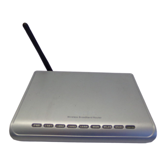
Page 32: Wireless Lan Application
P-320W User’s Guide 1.3.2 Wireless LAN Application Add a wireless LAN to your existing network without expensive network cables. Wireless stations can move freely anywhere in the coverage area and use resources on the wired network. Figure 2 Internet Access Application Example 1.3.3 Front Panel LEDs... - Page 33 P-320W User’s Guide Table 1 Front Panel LEDs (continued) COLOR STATUS DESCRIPTION LAN 1-4 Green The Prestige has a successful 10Mb Ethernet connection. Blinking The Prestige is sending/receiving data. Amber The Prestige has a successful 100Mb Ethernet connection. Blinking The Prestige is sending/receiving data.
- Page 34 P-320W User’s Guide Chapter 1 Getting to Know Your Prestige...
-
Page 35: Introducing The Web Configurator
P-320W User’s Guide H A P T E R Introducing the Web Configurator This chapter describes how to access the Prestige web configurator and provides an overview of its screens. 2.1 Web Configurator Overview The web configurator is an HTML-based management interface that allows easy Prestige setup and management via Internet browser. -
Page 36: Figure 4 Login
P-320W User’s Guide Figure 4 Login 5 Select your language. click Apply. Figure 5 Language Selection 6 You should see a screen asking you to change your password (highly recommended) as shown next. Type a new password (and retype it to confirm) and click Apply or click Ignore. -
Page 37: Resetting The Prestige
P-320W User’s Guide 7 Click Go to Wizard setup to do initial configuration withs the wizard, click Go to Advanced setup to configure advanced features, or click Exit to log out of the web configurator. Figure 7 Select the Mode Note: The management session automatically times out when the time period set in the Administrator Inactivity Timer field expires (default five minutes). -
Page 38: Figure 8 Web Configurator Status Screen
P-320W User’s Guide Figure 8 Web Configurator Status Screen The following table describes the icons shown in the Status screen. Table 2 Status Screen Icon Key ICON DESCRIPTION Select a language from the drop-down list box to have the the web configurator display in that language. -
Page 39: Navigation Panel
P-320W User’s Guide Table 3 Web Configurator Status Screen LABEL DESCRIPTION WAN Information - WAN Type This shows the encapsulation method (and service type) the Prestige is using. - IP Address This shows the WAN port’s IP address. - IP Subnet Mask This shows the WAN port’s subnet mask. - Page 40 P-320W User’s Guide Table 4 Screens Summary LINK FUNCTION Wireless LAN General Use this screen to configure wireless LAN. OTIST This screen allows you to assign wireless clients the Prestige’s wireless security settings. MAC Filter Use the MAC filter screen to configure the Prestige to block access to devices or block the devices from accessing the Prestige.
-
Page 41: Summary: Dhcp Table
P-320W User’s Guide Table 4 Screens Summary LINK FUNCTION Tools Firmware Use this screen to upload firmware to your Prestige. Configuration Use this screen to backup and restore the configuration or reset the factory defaults to your Prestige. Restart This screen allows you to reboot the Prestige without turning the power off. -
Page 42: Summary: Association List
P-320W User’s Guide 2.4.3 Summary: Association List Click the Association List (Detail) hyperlink in the Status screen. View the wireless stations that are currently associated to the Prestige in the Association List screen. Figure 10 Summary: Association List The following table describes the labels in this screen. -
Page 43: Figure 11 Summary: Packet Statistics
P-320W User’s Guide Figure 11 Summary: Packet Statistics The following table describes the labels in this screen. Table 7 Summary: Packet Statistics LABEL DESCRIPTION Port This is the WAN, LAN or WLAN port. TxPkts This is the number of transmitted packets on this port. - Page 44 P-320W User’s Guide Chapter 2 Introducing the Web Configurator...
-
Page 45: Chapter 3 Connection Wizard
P-320W User’s Guide H A P T E R Connection Wizard This chapter provides information on the Wizard setup screens in the web configurator. 3.1 Wizard Setup The web configurator’s Wizard setup helps you configure your device to access the Internet. -
Page 46: Connection Wizard: Step 1: System Information
P-320W User’s Guide Figure 13 Welcome to the Connection Wizard 3.2 Connection Wizard: STEP 1: System Information System Information contains administrative and system-related information. 3.2.1 System Name System Name is for identification purposes. However, because some ISPs check this name you should enter your computer's "Computer Name". -
Page 47: Connection Wizard: Step 2: Wireless Lan
P-320W User’s Guide Figure 14 Connection Wizard: STEP 1: System Information The following table describes the labels in this screen. Table 8 Connection Wizard: STEP 1: System Information LABEL DESCRIPTION System Name System Name is a unique name to identify the Prestige in an Ethernet network. Enter a descriptive name. -
Page 48: Figure 15 Connection Wizard: Step 2: Wireless Lan
P-320W User’s Guide Figure 15 Connection Wizard: STEP 2: Wireless LAN The following table describes the labels in this screen. Table 9 Connection Wizard: STEP 2: Wireless LAN LABEL DESCRIPTION Name(SSID) Enter a descriptive name (up to 32 printable 7-bit ASCII characters) for the wireless LAN. -
Page 49: Basic(Wep) Security
P-320W User’s Guide Note: The wireless stations and Prestige must use the same SSID, channel ID and WEP encryption key (if WEP is enabled), WPA-PSK (if WPA-PSK is enabled) for wireless communication. 3.3.1 Basic(WEP) Security Choose Basic(WEP) to setup WEP Encryption parameters. -
Page 50: Extend(Wpa-Psk) Security
P-320W User’s Guide Table 10 Basic(WEP) Security LABEL DESCRIPTION Key 1 to Key 4 The WEP keys are used to encrypt data. Both the Prestige and the wireless stations must use the same WEP key for data transmission. If you chose 64-bit WEP, then enter any 5 ASCII characters or 10 hexadecimal characters ("0-9", "A-F"). -
Page 51: Otist
P-320W User’s Guide The following table describes the labels in this screen. Table 11 Extend(WPA-PSK) Security LABEL DESCRIPTION Pre-Shared Type from 8 to 63 case-sensitive ASCII characters. You can set up the most secure wireless connection by configuring WPA in the wireless LAN screens. You need to configure an authentication server to do this. -
Page 52: Connection Wizard: Step 3: Internet Configuration
P-320W User’s Guide The following table describes the labels in this screen. Table 12 OTIST LABEL DESCRIPTION Do you want to Select the Yes radio button and click Next to proceed with the setup wizard and enable OTIST? enable OTIST only when you click Finish in the final wizard screen. -
Page 53: Ethernet Connection Type
P-320W User’s Guide The following table describes the labels in this screen, Table 13 Connection Wizard: STEP 3: WAN Connection Type CONNECTION TYPE DESCRIPTION Ethernet Select the Ethernet option when the WAN port is used as a regular Ethernet. PPPoE Select the PPP over Ethernet option for a dial-up connection. -
Page 54: Figure 21 Pppoe Connection Type
P-320W User’s Guide One of the benefits of PPPoE is the ability to let end users access one of multiple network services, a function known as dynamic service selection. This enables the service provider to easily create and offer new IP services for specific users. -
Page 55: Pptp Connection Type
P-320W User’s Guide 3.4.3 PPTP Connection Type Point-to-Point Tunneling Protocol (PPTP) is a network protocol that enables transfers of data from a remote client to a private server, creating a Virtual Private Network (VPN) using TCP/ IP-based networks. PPTP supports on-demand, multi-protocol, and virtual private networking over public networks, such as the Internet. -
Page 56: Your Ip Address
P-320W User’s Guide Table 15 PPTP Connection Type LABEL DESCRIPTION My IP Subnet Type the subnet mask assigned to you by your ISP (if given). Mask Server IP Type the IP address of the PPTP server. Address Connection ID/ Enter the connection ID or connection name in this field. It must follow the "c:id"... -
Page 57: Wan Mac Address
P-320W User’s Guide The following table describes the labels in this screen Table 16 Your IP Address LABEL DESCRIPTION Get automatically from Select this option If your ISP did not assign you a fixed IP address. This is the default selection. -
Page 58: Connection Wizard Complete
P-320W User’s Guide Figure 24 WAN MAC Address The following table describes the fields in this screen. Table 18 WAN MAC Address LABEL DESCRIPTION Factory Default Select Factory Default to use the factory assigned default MAC address. Spoof this Select this option and click Clone MAC to clone the MAC address in the MAC computer’s MAC... -
Page 59: Figure 25 Connection Wizard Complete
P-320W User’s Guide Figure 25 Connection Wizard Complete Click Finish to complete the wizard setup and save your configuration. Figure 26 Connection Wizard: Congratulation Well done! You have successfully set up your Prestige to operate on your network and access the Internet. - Page 60 P-320W User’s Guide Chapter 3 Connection Wizard...
-
Page 61: Chapter 4 Wireless Lan
P-320W User’s Guide H A P T E R Wireless LAN This chapter discusses how to configure Wireless LAN. 4.1 Introduction A wireless LAN can be as simple as two computers with wireless LAN adapters communicating in a peer-to-peer network or as complex as a number of computers with wireless LAN adapters communicating through access points which bridge network traffic to the wired LAN. -
Page 62: Restricted Access
P-320W User’s Guide 4.2.3 Restricted Access The MAC Filter screen allows you to configure the AP to give exclusive access to devices (Allow) or exclude them from accessing the AP (Deny). 4.2.4 Hide Prestige Identity If you hide the ESSID, then the Prestige cannot be seen when a wireless client scans for local APs. -
Page 63: General Wireless Lan Screen
P-320W User’s Guide The following figure shows the relative effectiveness of these wireless security methods available on your Prestige. Table 19 ZyAIR Wireless Security Levels Security Level Security Type Least Secure Unique SSID (Default) Unique SSID with Hide SSID Enabled... -
Page 64: No Security
P-320W User’s Guide The following table describes the general wireless LAN labels in this screen. Table 20 Wireless: General LABEL DESCRIPTION Enable Click the check box to activate wireless LAN. Wireless LAN Name(SSID) (Service Set IDentity) The SSID identifies the Service Set with which a wireless station is associated. -
Page 65: Wep Encryption
P-320W User’s Guide Figure 28 Wireless: No Security The following table describes the labels in this screen. Table 21 Wireless No Security LABEL DESCRIPTION Security Mode Choose No Security from the drop-down list box. Apply Click Apply to save your changes back to the Prestige. -
Page 66: Figure 29 Wireless: Static Wep Encryption
P-320W User’s Guide Figure 29 Wireless: Static WEP Encryption The following table describes the wireless LAN security labels in this screen. Table 22 Wireless: Static WEP Encryption LABEL DESCRIPTION Passphrase Enter a Passphrase (up to 32 printable characters) and clicking Generate. The Prestige automatically generates four different WEP keys. -
Page 67: Introduction To Wpa
P-320W User’s Guide Table 22 Wireless: Static WEP Encryption LABEL DESCRIPTION Key 1 to Key 4 The WEP keys are used to encrypt data. Both the Prestige and the wireless stations must use the same WEP key for data transmission. -
Page 68: Wpa-Psk Authentication Screen
P-320W User’s Guide Figure 30 WPA-PSK Authentication 4.4.5 WPA-PSK Authentication Screen In order to configure and enable WPA-PSK Authentication; click the Wireless LAN link under Network to display the General screen. Select WPA-PSK from the Security Mode list. Figure 31 Wireless: WPA-PSK The following table describes the labels in this screen. -
Page 69: Wpa With Radius Application Example
P-320W User’s Guide 4.4.6 WPA with RADIUS Application Example You need the IP address of the RADIUS server, its port number (default is 1812), and the RADIUS shared secret. A WPA application example with an external RADIUS server looks as follows. "A" is the RADIUS server. "DS" is the distribution system. -
Page 70: Ieee 802.1X Overview
P-320W User’s Guide Figure 33 Wireless: WPA The following table describes the labels in this screen. Table 24 Wireless: WPA LABEL DESCRIPTION Authentication Server IP Address Enter the IP address of the external authentication server in dotted decimal notation. Port Number Enter the port number of the external authentication server. -
Page 71: Ieee 802.1X And Dynamic Wep Key Exchange Screen
P-320W User’s Guide • A wireless station computer must be running IEEE 802.1x-compliant software. Not all Windows operating systems support IEEE 802.1x (see the Microsoft web site for details). For other operating systems, see their documentation. If your operating system does not support IEEE 802.1x, then you may need to install IEEE 802.1x client software. -
Page 72: Otist
P-320W User’s Guide Table 25 Wireless: 802.1x and Dynamic WEP LABEL DESCRIPTION Shared Secret Enter a password (up to 31 alphanumeric characters) as the key to be shared between the external authentication server and the Prestige. The key must be the same on the external authentication server and your Prestige. -
Page 73: Figure 35 Wireless: Otist
P-320W User’s Guide 4.5.1.1.2 Web Configurator Click the Wireless LAN link under Network and then the OTIST tab. The following screen displays. Figure 35 Wireless: OTIST The following table describes the labels in this screen. Table 26 Wireless: OTIST LABEL... -
Page 74: Wireless Client
The process takes three minutes to complete. 4.5.1.2 Wireless Client Start the ZyXEL utility and click the Adapter tab. Select the OTIST check box, enter the same Setup Key as your AP’s and click Save. Figure 36 Example Wireless Client OTIST Screen... -
Page 75: Starting Otist
Figure 39 OTIST in Progress (Client) • In the wireless client, you see this screen if it can't find an OTIST-enabled AP (with the same Setup key). Click OK to go back to the ZyXEL utility main screen. Figure 40 No AP with OTIST Found •... -
Page 76: Mac Filter
P-320W User’s Guide Figure 41 Start OTIST? 2 If an OTIST-enabled wireless client loses its wireless connection for more than ten seconds, it will search for an OTIST-enabled AP for up to one minute. (If you manually have the wireless client search for an OTIST-enabled AP, there is no timeout; click Cancel in the OTIST progress screen to stop the search.) -
Page 77: Figure 42 Wireless: Mac Address Filter
P-320W User’s Guide Figure 42 Wireless: MAC Address Filter The following table describes the labels in this menu. Table 27 MAC Address Filter LABEL DESCRIPTION Active Select Yes from the drop down list box to enable MAC address filtering. Define the filter action for the list of MAC addresses in the MAC Address table. -
Page 78: Wireless Lan Advanced Screen
P-320W User’s Guide 4.7 Wireless LAN Advanced Screen See the appendix for background information on roaming. To enable roaming on your Prestige, click the Wireless LAN link under Network and then the Advanced tab. The screen appears as shown. Figure 43 Wireless: Advanced The following table describes the labels in this screen. - Page 79 P-320W User’s Guide Table 28 Wireless: Advanced LABEL DESCRIPTION Apply Click Apply to save your changes back to the Prestige. Reset Click Reset to reload the previous configuration for this screen. Chapter 4 Wireless LAN...
- Page 80 P-320W User’s Guide Chapter 4 Wireless LAN...
-
Page 81: Chapter 5 Wan
P-320W User’s Guide H A P T E R This chapter describes how to configure WAN settings. 5.1 WAN IP Address Assignment Every computer on the Internet must have a unique IP address. If your networks are isolated from the Internet, for instance, only between your two branch offices, you can assign any IP addresses to the hosts without problems. -
Page 82: Dns Server Address Assignment
Use DNS (Domain Name System) to map a domain name to its corresponding IP address and vice versa, for instance, the IP address of www.zyxel.com is 204.217.0.2. The DNS server is extremely important because without it, you must know the IP address of a computer before you can access it. -
Page 83: Wan Mac Address
P-320W User’s Guide 2 Traffic Redirect (see Section 5.9 on page For example, if WAN has a metric of "1" and Traffic Redirect has a metric of "2", the WAN connection acts as the primary default route. If the WAN route fails to connect to the Internet, the Prestige tries Traffic Redirect next. -
Page 84: Figure 44 Wan: Ethernet Encapsulation
P-320W User’s Guide Figure 44 WAN: Ethernet Encapsulation The following table describes the labels in this screen. Table 31 WAN: Ethernet Encapsulation LABEL DESCRIPTION Encapsulation You must choose the Ethernet option when the WAN port is used as a regular Ethernet. -
Page 85: Pppoe Encapsulation
P-320W User’s Guide Table 31 WAN: Ethernet Encapsulation LABEL DESCRIPTION Spoof WAN MAC The MAC address section allows users to configure the WAN port's MAC address Address by either using the factory default or cloning the MAC address from a computer on your LAN. -
Page 86: Figure 45 Wan: Pppoe Encapsulation
P-320W User’s Guide Figure 45 WAN: PPPoE Encapsulation The following table describes the labels in this screen. Table 32 WAN: PPPoE Encapsulation LABEL DESCRIPTION ISP Parameters for Internet Access Encapsulation The PPP over Ethernet choice is for a dial-up connection using PPPoE. The Prestige supports PPPoE (Point-to-Point Protocol over Ethernet). -
Page 87: Pptp Encapsulation
P-320W User’s Guide Table 32 WAN: PPPoE Encapsulation LABEL DESCRIPTION Idle Timeout This value specifies the time in seconds that elapses before the router automatically disconnects from the PPPoE server. WAN IP Address Assignment Get automatically Select this option If your ISP did not assign you a fixed IP address. This is the from ISP default selection. -
Page 88: Figure 46 Pptp Encapsulation
P-320W User’s Guide Figure 46 PPTP Encapsulation The following table describes the labels in this screen. Table 33 PPTP Encapsulation LABEL DESCRIPTION ISP Parameters for Internet Access Encapsulation Point-to-Point Tunneling Protocol (PPTP) is a network protocol that enables secure transfer of data from a remote client to a private server, creating a Virtual Private Network (VPN) using TCP/IP-based networks. -
Page 89: Advanced Wan Screen
P-320W User’s Guide Table 33 PPTP Encapsulation LABEL DESCRIPTION Password Type the password associated with the User Name above. Retype to Confirm Type your password again to make sure that you have entered is correctly. Nailed-up Connection Select Nailed-Up Connection if you do not want the connection to time out. -
Page 90: Traffic Redirect
P-320W User’s Guide Figure 47 Advanced The following table describes the labels in this screen. Table 34 Advanced LABEL DESCRIPTION DNS Servers First DNS Server Enter the IP address(es) of the DNS server(s). If you do not configure a DNS server, you must know the IP address of a computer in order to access it. -
Page 91: Figure 49 Wan: Traffic Redirect
P-320W User’s Guide Figure 49 WAN: Traffic Redirect The following table describes the labels in this screen. Table 35 Traffic Redirect LABEL DESCRIPTION Active Select this check box to have the Prestige use traffic redirect if the normal WAN connection goes down. - Page 92 P-320W User’s Guide Chapter 5 WAN...
-
Page 93: Chapter 6 Lan
P-320W User’s Guide H A P T E R This chapter describes how to configure LAN settings. 6.1 LAN Overview Local Area Network (LAN) is a shared communication system to which many computers are attached. The LAN screens can help you configure a LAN DHCP server, manage IP addresses, and partition your physical network into logical networks. -
Page 94: Ip Address And Subnet Mask
P-320W User’s Guide 6.2.2 IP Address and Subnet Mask Refer to the section about IP address and subnet mask in the Wizard Setup chapter for this information. 6.3 IP Screen Click the LAN link under Network to open the IP screen. -
Page 95: Chapter 7 Dhcp Server
P-320W User’s Guide H A P T E R DHCP Server 7.1 DHCP DHCP (Dynamic Host Configuration Protocol, RFC 2131 and RFC 2132) allows individual clients to obtain TCP/IP configuration at start-up from a server. You can configure the Prestige as a DHCP server or disable it. -
Page 96: Static Dhcp Screen
P-320W User’s Guide The following table describes the labels in this screen. Table 37 General LABEL DESCRIPTION Enable DHCP Server DHCP (Dynamic Host Configuration Protocol, RFC 2131 and RFC 2132) allows individual clients (computers) to obtain TCP/IP configuration at startup from a server. -
Page 97: Client List Screen
P-320W User’s Guide Figure 52 Static DHCP The following table describes the labels in this screen. Table 38 Static DHCP LABEL DESCRIPTION This is the index number of the Static IP table entry (row). MAC Address Type the MAC address (with colons) of a computer on your LAN. -
Page 98: Figure 53 Client List
P-320W User’s Guide Figure 53 Client List The following table describes the labels in this screen. Table 39 Client List LABEL DESCRIPTION This is the index number of the host computer. IP Address This field displays the IP address relative to the # field listed above. -
Page 99: Network Address Translation (Nat)
P-320W User’s Guide H A P T E R Network Address Translation (NAT) This chapter discusses how to configure NAT on the Prestige. 8.1 NAT Overview NAT (Network Address Translation - NAT, RFC 1631) is the translation of the IP address of a host in a packet. -
Page 100: What Nat Does
P-320W User’s Guide Table 40 NAT Definitions TERM DESCRIPTION Inside This refers to the host on the LAN. Outside This refers to the host on the WAN. Local This refers to the packet address (source or destination) as the packet travels on the LAN. -
Page 101: Nat Application
P-320W User’s Guide Figure 54 How NAT Works 8.1.4 NAT Application The following figure illustrates a possible NAT application, where three inside LANs (logical LANs using IP Alias) behind the Prestige can communicate with three distinct WAN networks. More examples follow at the end of this chapter. -
Page 102: Port Forwarding: Services And Port Numbers
P-320W User’s Guide Note: If you do not assign a Default Server IP Address, the Prestige discards all packets received for ports that are not specified in this screen or remote management. 8.1.6 Port Forwarding: Services and Port Numbers A SUA server set is a list of inside (behind NAT on the LAN) servers, for example, web or FTP, that you can make accessible to the outside world even though NAT makes your whole inside network appear as a single machine to the outside world. -
Page 103: Configuring Servers Behind Sua (Example)
P-320W User’s Guide 8.1.7 Configuring Servers Behind SUA (Example) Let's say you want to assign ports 21-25 to one FTP, Telnet and SMTP server (A in the example), port 80 to another (B in the example) and assign a default server IP address of 192.168.1.35 to a third (C in the example). -
Page 104: Port Forwarding Screen
P-320W User’s Guide 8.3 Port Forwarding Screen Ordering your rules is important because the Prestige applies the rules in the order that you specify. When a rule matches the current packet, the Prestige takes the corresponding action and the remaining rules are ignored. If there are any empty rules before your new configured rule, your configured rule will be pushed up by that number of empty rules. -
Page 105: Rule Setup Screen
P-320W User’s Guide The following table describes the labels in this screen. Table 43 NAT: Port Forwarding LABEL DESCRIPTION Default Server In addition to the servers for specified services, NAT supports a default server. A default server receives packets from ports that are not specified in this screen. -
Page 106: Trigger Port Forwarding
P-320W User’s Guide The following table describes the labels in this screen. Table 44 NAT: Port Forwarding: Rule Setup LABEL DESCRIPTION Active Select the check box to enable this port forwarding entry. Clear the checkbox to disallow forwarding of these ports to an inside server without having to delete the entry. -
Page 107: Two Points To Remember About Trigger Ports
P-320W User’s Guide Figure 60 Trigger Port Forwarding Process: Example 1 Jane requests a file from the Real Audio server (port 7070). 2 Port 7070 is a “trigger” port and causes the Prestige to record Jane’s computer IP address. The Prestige associates Jane's computer IP address with the "incoming" port range of 6970-7170. -
Page 108: Figure 61 Nat: Trigger Port
P-320W User’s Guide Figure 61 NAT: Trigger Port The following table describes the labels in this screen. Table 45 NAT: Trigger Port LABEL DESCRIPTION This is the rule index number (read-only). Name Type a unique name (up to 15 characters) for identification purposes. All characters are permitted - including spaces. -
Page 109: Chapter 9 Firewall
P-320W User’s Guide H A P T E R Firewall This chapter gives some background information on firewalls and explains how to get started with the Prestige firewall. 9.1 Introduction to Firewall 9.1.1 What is a Firewall? Originally, the term firewall referred to a construction technique designed to prevent the spread of fire from one room to another. -
Page 110: Guidelines For Enhancing Security With Your Firewall
P-320W User’s Guide The Prestige has one Ethernet WAN port and four Ethernet LAN ports, which are used to physically separate the network into two areas.The WAN (Wide Area Network) port attaches to the broadband (cable or DSL) modem to the Internet. -
Page 111: Services Screen
P-320W User’s Guide The following table describes the labels in this screen. Table 46 Firewall: General LABEL DESCRIPTION Enable Firewall Select this check box to activate the firewall. The Prestige performs access control and protects against Denial of Service (DoS) attacks when the firewall is activated. -
Page 112: Table 47 Firewall: Services
P-320W User’s Guide The following table describes the labels in this screen. Table 47 Firewall: Services LABEL DESCRIPTION Enable Services Select this check box to enable this feature. Blocking Available Services This is a list of pre-defined services (ports) you may prohibit your LAN computers from using. -
Page 113: Services
P-320W User’s Guide 9.3.1 Services The commonly used services and port numbers are shown in the following table. Please refer to RFC 1700 for further information about port numbers. Next to the name of the service, two fields appear in brackets. The first field indicates the IP protocol type (TCP, UDP, or ICMP). -
Page 114: Pop3 (Post Office Protocol)
P-320W User’s Guide Table 48 Commonly Used Services SERVICE DESCRIPTION PING(ICMP:0) Packet INternet Groper is a protocol that sends out ICMP echo requests to test whether or not a remote host is reachable. POP3(TCP:110) Post Office Protocol version 3 lets a client computer get e-mail from a POP3 server through a temporary connection (TCP/IP or other). -
Page 115: Chapter 10 Static Route Screens
P-320W User’s Guide H A P T E R Static Route Screens This chapter shows you how to configure static routes for your Prestige. 10.1 Static Route Overview Each remote node specifies only the network to which the gateway is directly connected, and the Prestige has no knowledge of the networks beyond. -
Page 116: Static Route Setup Screen
P-320W User’s Guide Figure 65 IP Static Route The following table describes the labels in this screen. Table 49 IP Static Route LABEL DESCRIPTION Number of an individual static route. Active This icon is turned on when this static route is active. -
Page 117: Figure 66 Static Route Setup
P-320W User’s Guide Figure 66 Static Route Setup The following table describes the labels in this screen. Table 50 Static Route Setup LABEL DESCRIPTION Active This field allows you to activate/deactivate this static route. Destination IP This parameter specifies the IP network address of the final destination. Routing is Address always based on network number. - Page 118 P-320W User’s Guide Chapter 10 Static Route Screens...
-
Page 119: Remote Management Screens
P-320W User’s Guide H A P T E R Remote Management Screens This chapter provides information on the Remote Management screens. 11.1 Remote Management Overview Remote management allows you to determine which services/protocols can access which Prestige interface (if any) from which computers. -
Page 120: System Timeout
P-320W User’s Guide 11.1.3 System Timeout There is a default system management idle timeout of five minutes (three hundred seconds). The Prestige automatically logs you out if the management session remains idle for longer than this timeout period. The management session does not time out when a statistics screen is polling. -
Page 121: Snmp
P-320W User’s Guide 11.3 SNMP Simple Network Management Protocol (SNMP) is a protocol used for exchanging management information between network devices. SNMP is a member of the TCP/IP protocol suite. Your Prestige supports SNMP agent functionality, which allows a manager station to manage and monitor the Prestige through the network. -
Page 122: Supported Mibs
P-320W User’s Guide • Get - Allows the manager to retrieve an object variable from the agent. • GetNext - Allows the manager to retrieve the next object variable from a table or list within an agent. In SNMPv1, when a manager wants to retrieve all elements of a table from an agent, it initiates a Get operation, followed by a series of GetNext operations. -
Page 123: Security Screen
P-320W User’s Guide Figure 69 SNMP Remote Management The following table describes the labels in this screen. Table 53 SNMP Remote Management LABEL DESCRIPTION SNMP Configuration Get Community Enter the Get Community, which is the password for the incoming Get and GetNext requests from the management station. -
Page 124: Figure 70 Security Remote Management
P-320W User’s Guide Figure 70 Security Remote Management The following table describes the labels in this screen. Table 54 Security Remote Management LABEL DESCRIPTION ICMP Internet Control Message Protocol is a message control and error-reporting protocol between a host server and a gateway to the Internet. ICMP uses Internet Protocol (IP) datagrams, but the messages are processed by the TCP/IP software and directly apparent to the application user. -
Page 125: Chapter 12 Upnp
P-320W User’s Guide H A P T E R UP N P This chapter introduces the Universal Plug and Play feature. 12.1 Universal Plug and Play Overview Universal Plug and Play (UPnP) is a distributed, open networking standard that uses TCP/IP for simple peer-to-peer network connectivity between devices. -
Page 126: Upnp And Zyxel
Disable UPnP if this is not your intention. 12.2 UPnP and ZyXEL ZyXEL has achieved UPnP certification from the Universal Plug and Play Forum Creates UPnP™ Implementers Corp. (UIC). ZyXEL's UPnP implementation supports IGD 1.0 (Internet Gateway Device). At the time of writing ZyXEL's UPnP implementation supports Windows Messenger 4.6 and 4.7 while Windows Messenger 5.0 and Xbox are still being... -
Page 127: Installing Upnp In Windows Example
P-320W User’s Guide 12.4 Installing UPnP in Windows Example This section shows how to install UPnP in Windows Me and Windows XP. 12.4.1 Installing UPnP in Windows Me Follow the steps below to install UPnP in Windows Me. 1 Click Start and Control Panel. Double-click Add/Remove Programs. -
Page 128: Installing Upnp In Windows Xp
P-320W User’s Guide Figure 73 Add/Remove Programs: Windows Setup: Communication: Components 4 Click OK to go back to the Add/Remove Programs Properties window and click Next. 5 Restart the computer when prompted. 12.4.2 Installing UPnP in Windows XP Follow the steps below to install the UPnP in Windows XP. -
Page 129: Using Upnp In Windows Xp Example
Next. 12.5 Using UPnP in Windows XP Example This section shows you how to use the UPnP feature in Windows XP. You must already have UPnP installed in Windows XP and UPnP activated on the ZyXEL device. Chapter 12 UPnP... -
Page 130: Auto-Discover Your Upnp-Enabled Network Device
P-320W User’s Guide Make sure the computer is connected to a LAN port of the ZyXEL device. Turn on your computer and the ZyXEL device. 12.5.1 Auto-discover Your UPnP-enabled Network Device 1 Click Start and Control Panel. Double-click Network Connections. An icon displays under Internet Gateway. -
Page 131: Figure 78 Internet Connection Properties
P-320W User’s Guide Figure 78 Internet Connection Properties 4 You may edit or delete the port mappings or click Add to manually add port mappings. Figure 79 Internet Connection Properties: Advanced Settings Chapter 12 UPnP... -
Page 132: Figure 80 Internet Connection Properties: Advanced Settings: Add
P-320W User’s Guide Figure 80 Internet Connection Properties: Advanced Settings: Add 5 When the UPnP-enabled device is disconnected from your computer, all port mappings will be deleted automatically. 6 Select Show icon in notification area when connected option and click OK. An icon displays in the system tray. -
Page 133: Web Configurator Easy Access
12.5.2 Web Configurator Easy Access With UPnP, you can access the web-based configurator on the ZyXEL device without finding out the IP address of the ZyXEL device first. This is helpful if you do not know the IP address of the ZyXEL device. -
Page 134: Figure 84 Network Connections: My Network Places
P-320W User’s Guide Figure 84 Network Connections: My Network Places 6 Right-click on the icon for your Prestige and select Properties. A properties window displays with basic information about the Prestige. Figure 85 Network Connections: My Network Places: Properties: Example... -
Page 135: Chapter 13 System
P-320W User’s Guide H A P T E R System This chapter provides information on the System screens. 13.1 System Overview See the Wizard Setup chapter for more information on the next few screens. 13.2 General Screen Click the System link under Maintenance and the General tab. The following screen displays. -
Page 136: Dynamic Dns
P-320W User’s Guide The following table describes the labels in this screen. Table 56 System General LABEL DESCRIPTION System Name System Name is a unique name to identify the Prestige in an Ethernet network.. It is recommended you enter your computer’s “Computer name” in this field (see the Wizard Setup chapter for how to find your computer’s name). -
Page 137: Dynamic Dns Screen
P-320W User’s Guide 13.4 Dynamic DNS Screen To change your Prestige’s DDNS, click the System link under Maintenance and the Dynamic DNS tab. The screen appears as shown. Figure 87 Dynamic DNS The following table describes the labels in this screen. -
Page 138: Figure 88 Time Setting
P-320W User’s Guide Figure 88 Time Setting The following table describes the labels in this screen. Table 58 Time Setting LABEL DESCRIPTION Current Time and Date Current Time This field displays the time of your Prestige. Each time you reload this page, the Prestige synchronizes the time with the time server. - Page 139 P-320W User’s Guide Table 58 Time Setting LABEL DESCRIPTION Get from Time Select this radio button to have the Prestige get the time and date from the time Server server you specified below. Time Server Select the URL of your time server. Check with your ISP/network administrator if you are unsure of this information.
- Page 140 P-320W User’s Guide Chapter 13 System...
-
Page 141: Chapter 14 Logs
P-320W User’s Guide H A P T E R Logs This chapter contains information about configuring general log settings and viewing the Prestige’s logs. Refer to the appendices for example log message explanations. 14.1 View Log The web configurator allows you to look at all of the Prestige’s logs in one location. -
Page 142: Log Settings
P-320W User’s Guide The following table describes the labels in this screen. Table 59 View Log LABEL DESCRIPTION WAN Type This shows the encapsulation method (and service type) the Prestige is using and the firmware version. Display Time This displays the time this screen was refreshed. -
Page 143: Figure 90 Log Settings
P-320W User’s Guide Figure 90 Log Settings The following table describes the labels in this screen. Table 60 Log Settings LABEL DESCRIPTION E-mail Log Settings Mail Server Enter the server name or the IP address of the mail server for the e-mail addresses specified below. - Page 144 P-320W User’s Guide Table 60 Log Settings (continued) LABEL DESCRIPTION User Name Enter the user name (up to 31 characters) (usually the user name of a mail account). Password Enter the password associated with the user name above. Syslog Logging The Prestige sends a log to an external syslog server.
-
Page 145: Chapter 15 Tools
P-320W User’s Guide H A P T E R Tools This chapter shows you how to upload a new firmware, upload or save backup configuration files and restart the Prestige. 15.1 Firmware Upload Screen Find firmware at www.zyxel.com in a file that (usually) uses the system model name with a .bin extension, for example, "Prestige.bin". -
Page 146: Configuration Screen
P-320W User’s Guide Note: Do not turn off the Prestige while firmware upload is in progress! After you see the Firmware Upload In Process screen, wait two minutes before logging into the Prestige again. Figure 92 Upload Warning The Prestige automatically restarts in this time causing a temporary network disconnect. In some operating systems, you may see the following icon on your desktop. -
Page 147: Backup Configuration
P-320W User’s Guide Click the Tools link under Maintenance, and the Configuration tab. Information related to factory defaults, backup configuration, and restoring configuration appears as shown next. Figure 95 Configuration 15.2.1 Backup Configuration Backup configuration allows you to back up (save) the Prestige’s current configuration to a file on your computer. -
Page 148: Back To Factory Defaults
P-320W User’s Guide After you see a “Upgrade Successful” screen, you must then wait one minute before logging into the Prestige again. Figure 96 Configuration Restore Successful The Prestige automatically restarts in this time causing a temporary network disconnect. In some operating systems, you may see the following icon on your desktop. -
Page 149: Figure 99 System Restart
P-320W User’s Guide Figure 99 System Restart Chapter 15 Tools... - Page 150 P-320W User’s Guide Chapter 15 Tools...
-
Page 151: Chapter 16 Troubleshooting
P-320W User’s Guide H A P T E R Troubleshooting This chapter covers potential problems and the corresponding remedies. 16.1 Problems Starting Up the Prestige Table 63 Troubleshooting Starting Up Your Prestige PROBLEM CORRECTIVE ACTION None of the Make sure that the Prestige’s power adaptor is connected to the Prestige and plugged LEDs turn on in to an appropriate power source. -
Page 152: Problems With The Wan
P-320W User’s Guide 16.3 Problems with the WAN Table 65 Troubleshooting the WAN PROBLEM CORRECTIVE ACTION The WAN LED is Check the connections between the Prestige WAN port and the cable/DSL modem off. or ethernet jack. Check whether your cable/DSL device requires a crossover or straight-through cable. -
Page 153: Problems With Remote Management
P-320W User’s Guide 16.5 Problems with Remote Management Table 67 Troubleshooting Telnet PROBLEM CORRECTIVE ACTION Cannot access the Refer to Section 11.1.1 on page 119 for scenarios when remote management Prestige from the may not be possible. LAN or WAN. -
Page 154: Pop-Up Windows, Javascripts And Java Permissions
P-320W User’s Guide 16.6.1 Pop-up Windows, JavaScripts and Java Permissions In order to use the web configurator you need to allow: • Web browser pop-up windows from your device. • JavaScripts (enabled by default). • Java permissions (enabled by default). -
Page 155: Figure 101 Internet Options
P-320W User’s Guide Figure 101 Internet Options 3 Click Apply to save this setting. 16.6.1.1.2 Enable pop-up Blockers with Exceptions Alternatively, if you only want to allow pop-up windows from your device, see the following steps. 1 In Internet Explorer, select Tools, Internet Options and then the Privacy tab. -
Page 156: Figure 102 Internet Options
P-320W User’s Guide Figure 102 Internet Options 3 Type the IP address of your device (the web page that you do not want to have blocked) with the prefix “http://”. For example, http://192.168.1.1. 4 Click Add to move the IP address to the list of Allowed sites. -
Page 157: Javascripts
P-320W User’s Guide Figure 103 Pop-up Blocker Settings 5 Click Close to return to the Privacy screen. 6 Click Apply to save this setting. 16.6.1.2 JavaScripts If pages of the web configurator do not display properly in Internet Explorer, check that JavaScripts are allowed. -
Page 158: Figure 104 Internet Options
P-320W User’s Guide Figure 104 Internet Options 2 Click the Custom Level... button. 3 Scroll down to Scripting. 4 Under Active scripting make sure that Enable is selected (the default). 5 Under Scripting of Java applets make sure that Enable is selected (the default). -
Page 159: Java Permissions
P-320W User’s Guide Figure 105 Security Settings - Java Scripting 16.6.1.3 Java Permissions 1 From Internet Explorer, click Tools, Internet Options and then the Security tab. 2 Click the Custom Level... button. 3 Scroll down to Microsoft VM. 4 Under Java permissions make sure that a safety level is selected. -
Page 160: Figure 106 Security Settings - Java
P-320W User’s Guide Figure 106 Security Settings - Java 16.6.1.3.1 JAVA (Sun) 1 From Internet Explorer, click Tools, Internet Options and then the Advanced tab. 2 Make sure that Use Java 2 for <applet> under Java (Sun) is selected. 3 Click OK to close the window. -
Page 161: Activex Controls In Internet Explorer
P-320W User’s Guide 16.6.2 ActiveX Controls in Internet Explorer If ActiveX is disabled, you will not be able to download ActiveX controls or to use Trend Micro Security Serivces. Make sure that ActiveX controls are allowed in Internet Explorer. Screen shots for Internet Explorer 6 are shown. Steps may vary depending on your version of Internet Explorer. -
Page 162: Figure 109 Security Setting Activex Controls
P-320W User’s Guide Figure 109 Security Setting ActiveX Controls Chapter 16 Troubleshooting... -
Page 163: Product Specifications
P-320W User’s Guide P P E N D I X Product Specifications See also the Introduction chapter for a general overview of the key features. Specification Tables Table 69 Device Default IP Address 192.168.1.1 Default Subnet Mask 255.255.255.0 (24 bits) - Page 164 P-320W User’s Guide Table 70 Firmware (continued) Wireless IEEE 802.11g Compliance Frequency Range: 2.4 GHz Advanced Orthogonal Frequency Division Multiplexing (OFDM) Data Rates: 54Mbps and Auto Fallback Wired Equivalent Privacy (WEP) Data Encryption 64/128/256 bit. WLAN bridge to LAN Up to 32 MAC Address filters...
-
Page 165: Appendix Bip Subnetting
P-320W User’s Guide P P E N D I X IP Subnetting IP Addressing Routers “route” based on the network number. The router that delivers the data packet to the correct destination host uses the host ID. IP Classes An IP address is made up of four octets (eight bits), written in dotted decimal notation, for example, 192.168.1.1. -
Page 166: Table 72 Allowed Ip Address Range By Class
P-320W User’s Guide Since the first octet of a class “A” IP address must contain a “0”, the first octet of a class “A” address can have a value of 0 to 127. Similarly the first octet of a class “B” must begin with “10”, therefore the first octet of a class “B”... -
Page 167: Table 74 Alternative Subnet Mask Notation
P-320W User’s Guide Since the mask is always a continuous number of ones beginning from the left, followed by a continuous number of zeros for the remainder of the 32 bit mask, you can simply specify the number of ones instead of writing the value of each octet. This is usually specified by writing a “/”... -
Page 168: Table 76 Subnet 1
P-320W User’s Guide Note: In the following charts, shaded/bolded last octet bit values indicate host ID bits “borrowed” to form network ID bits. The number of “borrowed” host ID bits determines the number of subnets you can have. The remaining number of host ID bits (after “borrowing”) determines the number of hosts you can have... -
Page 169: Table 78 Subnet 1
P-320W User’s Guide Example: Four Subnets The above example illustrated using a 25-bit subnet mask to divide a class “C” address space into two subnets. Similarly to divide a class “C” address into four subnets, you need to “borrow” two host ID bits to give four possible combinations of 00, 01, 10 and 11. The subnet mask is 26 bits (11111111.11111111.11111111.11000000) or 255.255.255.192. -
Page 170: Table 81 Subnet 4
P-320W User’s Guide Table 81 Subnet 4 NETWORK NUMBER LAST OCTET BIT VALUE IP Address 192.168.1. IP Address (Binary) 11000000.10101000.00000001. 11000000 Subnet Mask (Binary) 11111111.11111111.11111111. 11000000 Subnet Address: Lowest Host ID: 192.168.1.193 192.168.1.192 Broadcast Address: Highest Host ID: 192.168.1.254 192.168.1.255 Example Eight Subnets Similarly use a 27-bit mask to create 8 subnets (001, 010, 011, 100, 101, 110). -
Page 171: Table 84 Class B Subnet Planning
P-320W User’s Guide Subnetting With Class A and Class B Networks. For class “A” and class “B” addresses the subnet mask also determines which bits are part of the network number and which are part of the host ID. A class “B” address has two host ID octets available for subnetting and a class “A” address has... - Page 172 P-320W User’s Guide Appendix B IP Subnetting...
-
Page 173: Setting Up Your Computer's Ip Address
P-320W User’s Guide P P E N D I X Setting up Your Computer’s IP Address All computers must have a 10M or 100M Ethernet adapter card and TCP/IP installed. Windows 95/98/Me/NT/2000/XP, Macintosh OS 7 and later operating systems and all versions of UNIX/LINUX include the software components you need to install and use TCP/ IP on your computer. -
Page 174: Figure 110 Windows 95/98/Me: Network: Configuration
P-320W User’s Guide Figure 110 WIndows 95/98/Me: Network: Configuration Installing Components The Network window Configuration tab displays a list of installed components. You need a network adapter, the TCP/IP protocol and Client for Microsoft Networks. If you need the adapter: 1 In the Network window, click Add. -
Page 175: Figure 111 Windows 95/98/Me: Tcp/Ip Properties: Ip Address
P-320W User’s Guide 3 Select Microsoft from the list of manufacturers. 4 Select Client for Microsoft Networks from the list of network clients and then click 5 Restart your computer so the changes you made take effect. Configuring 1 In the Network window Configuration tab, select your network adapter's TCP/IP entry and click Properties 2 Click the IP Address tab. -
Page 176: Figure 112 Windows 95/98/Me: Tcp/Ip Properties: Dns Configuration
P-320W User’s Guide Figure 112 Windows 95/98/Me: TCP/IP Properties: DNS Configuration 4 Click the Gateway tab. • If you do not know your gateway’s IP address, remove previously installed gateways. • If you have a gateway IP address, type it in the New gateway field and click Add. -
Page 177: Figure 113 Windows Xp: Start Menu
P-320W User’s Guide Figure 113 Windows XP: Start Menu 2 In the Control Panel, double-click Network Connections (Network and Dial-up Connections in Windows 2000/NT). Figure 114 Windows XP: Control Panel 3 Right-click Local Area Connection and then click Properties. Appendix C Setting up Your Computer’s IP Address... -
Page 178: Figure 115 Windows Xp: Control Panel: Network Connections: Properties
P-320W User’s Guide Figure 115 Windows XP: Control Panel: Network Connections: Properties 4 Select Internet Protocol (TCP/IP) (under the General tab in Win XP) and then click Properties. Figure 116 Windows XP: Local Area Connection Properties 5 The Internet Protocol TCP/IP Properties window opens (the General tab in Windows XP). -
Page 179: Figure 117 Windows Xp: Internet Protocol (Tcp/Ip) Properties
P-320W User’s Guide • If you have a static IP address click Use the following IP Address and fill in the IP address, Subnet mask, and Default gateway fields. • Click Advanced. Figure 117 Windows XP: Internet Protocol (TCP/IP) Properties 6 If you do not know your gateway's IP address, remove any previously installed gateways in the IP Settings tab and click OK. -
Page 180: Figure 118 Windows Xp: Advanced Tcp/Ip Properties
P-320W User’s Guide Figure 118 Windows XP: Advanced TCP/IP Properties 7 In the Internet Protocol TCP/IP Properties window (the General tab in Windows XP): • Click Obtain DNS server address automatically if you do not know your DNS server IP address(es). -
Page 181: Figure 119 Windows Xp: Internet Protocol (Tcp/Ip) Properties
P-320W User’s Guide Figure 119 Windows XP: Internet Protocol (TCP/IP) Properties 8 Click OK to close the Internet Protocol (TCP/IP) Properties window. 9 Click Close (OK in Windows 2000/NT) to close the Local Area Connection Properties window. 10 Close the Network Connections window (Network and Dial-up Connections in Windows 2000/NT). -
Page 182: Figure 120 Macintosh Os 8/9: Apple Menu
P-320W User’s Guide Figure 120 Macintosh OS 8/9: Apple Menu 2 Select Ethernet built-in from the Connect via list. Figure 121 Macintosh OS 8/9: TCP/IP 3 For dynamically assigned settings, select Using DHCP Server from the Configure: list. Appendix C Setting up Your Computer’s IP Address... -
Page 183: Figure 122 Macintosh Os X: Apple Menu
P-320W User’s Guide 4 For statically assigned settings, do the following: • From the Configure box, select Manually. • Type your IP address in the IP Address box. • Type your subnet mask in the Subnet mask box. • Type the IP address of your Prestige in the Router address box. -
Page 184: Figure 123 Macintosh Os X: Network
P-320W User’s Guide Figure 123 Macintosh OS X: Network 4 For statically assigned settings, do the following: • From the Configure box, select Manually. • Type your IP address in the IP Address box. • Type your subnet mask in the Subnet mask box. -
Page 185: Figure 124 Red Hat 9.0: Kde: Network Configuration: Devices
P-320W User’s Guide Note: Make sure you are logged in as the root administrator. Using the K Desktop Environment (KDE) Follow the steps below to configure your computer IP address using the KDE. 1 Click the Red Hat button (located on the bottom left corner), select System Setting and click Network. -
Page 186: Figure 126 Red Hat 9.0: Kde: Network Configuration: Dns
P-320W User’s Guide • If you have a dynamic IP address, click Automatically obtain IP address settings with and select dhcp from the drop down list. • If you have a static IP address, click Statically set IP Addresses and fill in the Address, Subnet mask, and Default Gateway Address fields. -
Page 187: Figure 128 Red Hat 9.0: Dynamic Ip Address Setting In Ifconfig-Eth0
P-320W User’s Guide 1 Assuming that you have only one network card on the computer, locate the ifconfig- configuration file (where is the name of the Ethernet card). Open the eth0 eth0 configuration file with any plain text editor. •... -
Page 188: Figure 131 Red Hat 9.0: Restart Ethernet Card
P-320W User’s Guide Figure 131 Red Hat 9.0: Restart Ethernet Card [root@localhost init.d]# network restart Shutting down interface eth0: [OK] Shutting down loopback interface: [OK] Setting network parameters: [OK] Bringing up loopback interface: [OK] Bringing up interface eth0: [OK] Verifying Settings Enter in a terminal screen to check your TCP/IP properties. -
Page 189: Appendix Dpppoe
P-320W User’s Guide P P E N D I X PPPoE PPPoE in Action An ADSL modem bridges a PPP session over Ethernet (PPP over Ethernet, RFC 2516) from your computer to an ATM PVC (Permanent Virtual Circuit) which connects to a DSL Access... -
Page 190: Figure 133 Single-Computer Per Router Hardware Configuration
P-320W User’s Guide Figure 133 Single-Computer per Router Hardware Configuration How PPPoE Works The PPPoE driver makes the Ethernet appear as a serial link to the computer and the computer runs PPP over it, while the modem bridges the Ethernet frames to the Access Concentrator (AC). -
Page 191: Appendix Epptp
P-320W User’s Guide P P E N D I X PPTP What is PPTP? PPTP (Point-to-Point Tunneling Protocol) is a Microsoft proprietary protocol (RFC 2637 for PPTP is informational only) to tunnel PPP frames. How can we transport PPP frames from a computer to a broadband... -
Page 192: Figure 136 Pptp Protocol Overview
P-320W User’s Guide PPTP Protocol Overview PPTP is very similar to L2TP, since L2TP is based on both PPTP and L2F (Cisco’s Layer 2 Forwarding). Conceptually, there are three parties in PPTP, namely the PNS (PPTP Network Server), the PAC (PPTP Access Concentrator) and the PPTP user. The PNS is the box that hosts both the PPP and the PPTP stacks and forms one end of the PPTP tunnel. -
Page 193: Figure 137 Example Message Exchange Between Computer And An Ant
P-320W User’s Guide Figure 137 Example Message Exchange between Computer and an ANT PPP Data Connection The PPP frames are tunneled between the PNS and PAC over GRE (General Routing Encapsulation, RFC 1701, 1702). The individual calls within a tunnel are distinguished using the Call ID field in the GRE header. - Page 194 P-320W User’s Guide Appendix E PPTP...
-
Page 195: Appendix F Wireless Lans
P-320W User’s Guide P P E N D I X Wireless LANs Wireless LAN Topologies This section discusses ad-hoc and infrastructure wireless LAN topologies. Ad-hoc Wireless LAN Configuration The simplest WLAN configuration is an independent (Ad-hoc) WLAN that connects a set of computers with wireless stations (A, B, C). -
Page 196: Figure 139 Basic Service Set
P-320W User’s Guide Figure 139 Basic Service Set An Extended Service Set (ESS) consists of a series of overlapping BSSs, each containing an access point, with each access point connected together by a wired network. This wired connection between APs is called a Distribution System (DS). -
Page 197: Figure 140 Infrastructure Wlan
P-320W User’s Guide Figure 140 Infrastructure WLAN Channel A channel is the radio frequency(ies) used by IEEE 802.11a/b/g wireless devices. Channels available depend on your geographical area. You may have a choice of channels (for your region) so you should use a different channel than an adjacent AP (access point) to reduce interference. -
Page 198: Figure 141 Rts/Cts
P-320W User’s Guide Figure 141 RTS/CTS When station A sends data to the AP, it might not know that the station B is already using the channel. If these two stations send data at the same time, collisions may occur when both sets of data arrive at the AP at the same time, resulting in a loss of messages for both stations. -
Page 199: Table 85 Ieee802.11G
P-320W User’s Guide A large Fragmentation Threshold is recommended for networks not prone to interference while you should set a smaller threshold for busy networks or networks that are prone to interference. If the Fragmentation Threshold value is smaller than the RTS/CTS value (see previously) you set then the RTS (Request To Send)/CTS (Clear to Send) handshake will never occur as data frames will be fragmented before they reach RTS/CTS size. -
Page 200: Types Of Radius Messages
P-320W User’s Guide IEEE 802.1x In June 2001, the IEEE 802.1x standard was designed to extend the features of IEEE 802.11 to support extended authentication as well as providing additional accounting and control features. It is supported by Windows XP and a number of network devices. Some advantages of IEEE 802.1x are:... -
Page 201: Figure 142 Eap Authentication
P-320W User’s Guide • Access-Challenge Sent by a RADIUS server requesting more information in order to allow access. The access point sends a proper response from the user and then sends another Access- Request message. The following types of RADIUS messages are exchanged between the access point and the RADIUS server for user accounting: •... -
Page 202: Types Of Authentication
P-320W User’s Guide 3 The wireless station replies with identity information, including username and password. 4 The RADIUS server checks the user information against its user profile database and determines whether or not to authenticate the wireless station. Types of Authentication This section discusses some popular authentication types: EAP-MD5, EAP-TLS, EAP- TTLS, PEAP and LEAP. - Page 203 P-320W User’s Guide PEAP (Protected EAP) Like EAP-TTLS, server-side certificate authentication is used to establish a secure connection, then use simple username and password methods through the secured connection to authenticate the clients, thus hiding client identity. However, PEAP only supports EAP methods, such as EAP-MD5, EAP-MSCHAPv2 and EAP-GTC (EAP-Generic Token Card), for client authentication.
-
Page 204: Figure 143 Wep Authentication Steps
P-320W User’s Guide Figure 143 WEP Authentication Steps Open system authentication involves an unencrypted two-message procedure. A wireless station sends an open system authentication request to the AP, which will then automatically accept and connect the wireless station to the network. In effect, open system is not authentication at all as any station can gain access to the network. -
Page 205: Table 86 Comparison Of Eap Authentication Types
P-320W User’s Guide Note: EAP-MD5 cannot be used with Dynamic WEP Key Exchange For added security, certificate-based authentications (EAP-TLS, EAP-TTLS and PEAP) use dynamic keys for data encryption. They are often deployed in corporate environments, but for public deployment, a simple user name and password pair is more practical. The following table is a comparison of the features of authentication types. -
Page 206: Table 87 Wireless Security Relational Matrix
P-320W User’s Guide The Message Integrity Check (MIC) is designed to prevent an attacker from capturing data packets, altering them and resending them. The MIC provides a strong mathematical function in which the receiver and the transmitter each compute and then compare the MIC. If they do not match, it is assumed that the data has been tampered with and the packet is dropped. -
Page 207: Figure 144 Roaming Example
P-320W User’s Guide In a network environment with multiple access points, wireless stations are able to switch from one access point to another as they move between the coverage areas. This is roaming. As the wireless station moves from place to place, it is responsible for choosing the most appropriate access point depending on the signal strength, network utilization or other factors. -
Page 208: Requirements For Roaming
P-320W User’s Guide Requirements for Roaming The following requirements must be met in order for wireless stations to roam between the coverage areas. 1 All the access points must be on the same subnet and configured with the same ESSID. -
Page 209: Antenna Selection And Positioning Recommendation
P-320W User’s Guide P P E N D I X Antenna Selection and Positioning Recommendation An antenna couples RF signals onto air. A transmitter within a wireless device sends an RF signal to the antenna, which propagates the signal through the air. The antenna also operates in reverse by capturing RF signals from the air. -
Page 210: Types Of Antennas For Wlan
P-320W User’s Guide Types of Antennas For WLAN There are two types of antennas used for wireless LAN applications. • Omni-directional antennas send the RF signal out in all directions on a horizontal plane. The coverage area is torus-shaped (like a donut) which makes these antennas ideal for a room environment. - Page 211 P-320W User’s Guide Index Numerics Certifications Changes or Modifications Channel 110V AC Interference 230V AC Channel ID 802.1x Charge Circuit Class B Communications Compliance, FCC Components Abnormal Working Conditions Condition Configuration 41, 95 Accessories Connecting Cables Acts of God Consequential Damages...
- Page 212 P-320W User’s Guide Dynamic DNS Dynamic WEP Key Exchange DYNDNS Wildcard Gas Pipes General Setup General wireless LAN screen Germany, Contact Information Global God, act of EAP Authentication 201, 202 ECHO Electric Shock Electrical Pipes Electrocution Harmful Interference Encryption Hidden node...
- Page 213 P-320W User’s Guide OTIST OTIST Wizard Out-dated Warranty Labor Outlet LAN Setup 81, 93 Outside LAN TCP/IP Legal Rights Liability License Lightning Liquids, Corrosive Packet statistics Local Pairwise Master Key (PMK) Parts Patent Permission Photocopying Pipes MAC Address Filter Action...
- Page 214 P-320W User’s Guide Radio Frequency Energy Service Type Radio Interference Services 102, 111 Radio Reception Shipping Radio Technician Shock, Electric RADIUS SMTP Shared Secret Key SNMP 102, 110, 121 RADIUS Message Types Manager MIBs RADIUS Messages Spain, Contact Information Receiving Antenna...
- Page 215 P-320W User’s Guide Workmanship Worldwide Contact Information Undesired Operations Written Permission Universal Plug and Play (UPnP) User Authentication User Name ZyNOS ZyXEL Communications Corporation ZyXEL Home Page Value ZyXEL Limited Warranty Vendor Note Ventilation Slots ZyXEL Network Operating System Viewing Certifications...