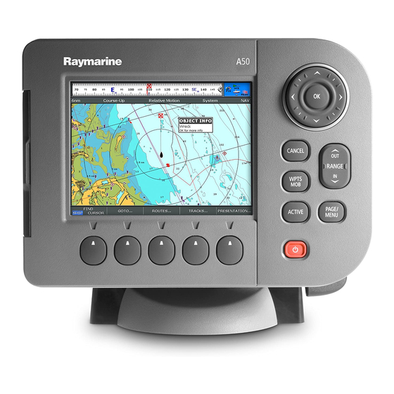
Raymarine A Series A50 User's Reference Manual
A-series multi-function display
Hide thumbs
Also See for A Series A50:
- Installation instructions manual (60 pages) ,
- Quick reference manual (8 pages)

Related Manuals for Raymarine A Series A50


Summary of Contents for Raymarine A Series A50
- Page 1 A-Series Multi-function display User reference manual A50, A50D, A57D, A70 and A70D models...
- Page 2 Trademarks and registered trademarks Autohelm, HSB, RayTech Navigator, Sail Pilot, SeaTalk and Sportpi- lot are UK registered trademarks of Raymarine UK Limited. Pathfinder and Raymarine are UK registered trademarks of Rayma- rine Holdings Limited. 45STV, 60STV, AST, Autoadapt, Auto GST,...
-
Page 3: Table Of Contents
Contents Important information..........9 Split screen pages............26 Emergencies and warnings ........27 Warnings and Cautions ............ 9 Electronic charts ............. 10 Man overboard ..............27 Alarms ................27 Chapter 2:Using the display......... 13 Chapter 3:Waypoints ..........29 Introduction ............. 14 Introducing waypoints..........30 System overview ............. - Page 4 Creating a route ............42 Chapter 5:3D chart application ......63 Following a route .............44 Safety and system requirements ......64 Safety................64 Editing routes ............45 Requirements..............64 Timed routes ..............46 3D chart operation ..........64 Course deviation indicator ........47 The controls ..............65 Using tracks .............48 Active and Planning modes ..........
- Page 5 Presentation options ..........79 Tropical storm data............92 Lightning................92 Gain and power ............. 79 Surface observation stations ...........92 Power setting ..............80 City forecasts..............92 Dual / Single frequency view .......... 80 Wind ................93 Measuring depth and distance........81 Waves ................93 Adjusting the scroll mode and speed......82 Surface pressure .............94 Placing waypoints ...........
- Page 6 Chapter 9:Navtex ..........105 Messages and alarms ........... 116 Safety messages ............116 Setting up Navtex ..........106 AIS alarms ............116 Selecting message alert categories .......106 Active alarm list............. 116 The Navtex message window ........106 Chapter 11:Data and Engine monitors....119 Managing Navtex messages .........107 System requirements ..........
- Page 7 Contacting Raymarine........... 146 COG/SOG filter............. 128 System-wide settings ..........129 Using the website ............146 In the US ...............146 System Setup menu ............. 129 In Europe...............147 Alarm Setup Menu ............131 Worldwide..............147 Chapter 13:Storing data and Chart / CF cards . 135 Contacting Navionics..........
- Page 8 A-Series display - User reference manual...
-
Page 9: Important Information
This can be confirmed by an This equipment must be installed in accordance audible click. with the Raymarine instructions provided. Failure to do so could result in poor product performance, CAUTION: Sun covers personal injury, and/or damage to your boat. -
Page 10: Electronic Charts
Raymarine does not warrant that this product is error-free or that it is To check the current availability of Navionics chart card types and compatible with products manufactured by any person or entity the latest feature sets, visit www.navionics.com... -
Page 11: Declaration Of Conformity
Product disposal To the best of our knowledge, the information in this handbook was correct as it went to press. However, Raymarine cannot accept lia- The Waste Electrical and Electronic Equipment (WEEE) bility for any inaccuracies or omissions it may contain. In addition,... - Page 12 A-Series display - User reference manual...
-
Page 13: Chapter 2:Using The Display
Chapter 2: Using the display This chapter gives details of the general operation of the A-Series display. Chapter contents • 2.1 Introduction on page 14 • 2.2 System overview on page 14 • 2.3 Applications on page 16 • 2.4 First time use on page 17 •... -
Page 14: Introduction
2.1 Introduction 2.2 System overview The A-Series Multifunction display combines advanced chart plot- ting and high definition digital fishfinder technology within a compact Core System and powerful navigation system. Your A-Series Multifunction Display comes equipped with a VGA (640 x 280 pixel) TFT 256 color sunlight viewable display and an internal high sensitivity GPS module. -
Page 15: Extended System
Extended System Your A-Series may connect to other equipment, for example to share data. Example extended system NMEA 0183 devices A-Series display Example: External AIS receiver Instrument SeaTalk devices Pilot CANCEL ENTER CANCEL ENTER MENU MENU SeaTalk NMEA SeaTalk NMEA 0183 converter Sonar SeaTalk... -
Page 16: Applications
2.3 Applications Fishfinder (D Models only) The A-Series features are provided within a number of applications. • See where the fish are. Some applications are limited to certain models. • Identify underwater objects. Chartplotter • View seabed structure. • Locate where you are •... -
Page 17: First Time Use
NMEA 2000 or SeaTalk Turn on the display To Power ON: Press and hold the POWER key until the screen shows the Raymarine logo. 3d chart Select a page set. Requires upgraded cartography (chart card). When you first turn the display on you will be prompted to select a page set from those available. - Page 18 Simulator Your A-Series display includes a simulator mode that enables you to practice operating the unit without data from a GPS antenna or transducer unit. Note: The simulator will NOT display any real-data, including any safety messages (e.g. those received from AIS). To turn the simulator ON or OFF: 1.
-
Page 19: Controls
2.5 Controls Trackpad Controls the on-screen cursor. Also used to scroll through menus. Press the correspnding edge of the trackpad to move the cursor horizontally, vertically or CANCEL WPTS/MOB Press to quit the selected diagonally. Press and release to display the on-screen option when editing data. -
Page 20: Operation
Press and hold the POWER key until the screen shows time, it changes to a circle with a cross in it, to make it the Raymarine logo. The unit starts up in the last used easier to locate on screen. -
Page 21: Display Lighting And Color
To Zoom in or out Note: The display saves the current palette when the unit is powered off. A display set to NIGHT may be difficult to see in Use the RANGE button to change the scale of the bright sunlight. viewable area. -
Page 22: Additional Screen Information
2.7 Additional screen information Status bar Data bar Status icons • • Gives information specific to Gives information associated with Confirm status of each application. your boat or the environment. Sounder, GPS, AIS and • • Cannot be edited or moved. Customisable content. -
Page 23: Compass Bar
Toolbars and softkeys WAYPOINT AT WAYPOINT AT WAYPOINT AT GO TO WAYPOINT REVIEW AND EDIT Active waypoint CURSOR VESSEL LAT/LONG... OPTIONS… WAYPOINTS A toolbar is a set of softkey labels which appear along the bottom of Bearing marker Steer direction an application page or window. -
Page 24: Setup Menus
Setup menus See also For full details of the setup menus and available settings refer to Menus are provided for you to make system or application changes. System Setup and Customizing on page 125. To use the Setup menus 1. Press and hold the PAGE/MENU button to open the Setup menu. Dialog boxes 2. -
Page 25: Displaying Applications
2.8 Displaying applications 2. Enter the data. Press OK to save the changes. The various applications that make up your A-Series system are e.g. arranged in groups called page sets. Symbol Name Waypoint 1 Selecting a page set My Waypoints Group To select a page set: Comment... -
Page 26: Split Screen Pages
2. Either select the application page you want from the toolbar or To change the active window toggle between the applications configured in the page set by 1. Press ACTIVE to toggle active status between windows (the red pressing PAGE/MENU. border moves to highlight the active window). -
Page 27: Emergencies And Warnings
2.9 Emergencies and warnings • Navigation functions are suspended and no new GOTO or route functions are selectable. You can use your A-Series display to mark the position of a man • Motion mode on the chart application is changed to autorange overboard (MOB) or to sound an alarm when a particular situation to show the largest possible scale of chart that will include both occurs, e.g. - Page 28 • System alarms are triggered by A-Series applications, i.e the chart or fishfinder. When you cancel a system alarm, the A-Se- ries cancels the alarm and makes appropriate changes to the application that triggered it. For example, if the chart application sounds an arrival alarm, navigation to the next waypoint in the route starts when you cancel the alarm.
-
Page 29: Chapter 3:Waypoints
Chapter 3: Waypoints This chapter introduces waypoints and explains how to use them for navigation with your A-Series Multifunction Display. Chapter contents • 3.1 Introducing waypoints on page 30 • 3.2 Using Waypoints on page 31 • 3.3 Waypoint groups on page 35... -
Page 30: Introducing Waypoints
3.1 Introducing waypoints Fishfinder waypoints On a fishfinder screen the waypoint appears as a vertical line A waypoint is a position marked on a chart or fishfinder screen as a labelled WPT. This representation cannot be changed. reference point or as a place to go to and can be used as a building block when creating routes. -
Page 31: Using Waypoints
3.2 Using Waypoints 3D chart and CDI waypoints On a 3D chart or Course Deviation Indicator (CDI) only the active This section details the creation, navigation and editing of waypoint is shown. waypoints. The waypoint toolbar You can use the waypoint toolbar to create, edit and navigate to waypoints. -
Page 32: Navigating To Waypoints
2. Using the trackpad move the cursor to the position where you Note: Autopilots must be compatible and connected to the A- want the waypoint. Series display as shown in the installation guide. 3. Press the WAYPOINT AT CURSOR softkey. For detailed information on navigating with waypoints, see The chart 4. -
Page 33: View / Edit Waypoint Details
View / edit waypoint details Editing waypoint details When you create a waypoint, the system automatically assigns it a You can view and edit the details of any waypoint that has been cre- name, symbol and group. You can change these details and add ated and stored. -
Page 34: Moving Waypoints
Moving waypoints 2. Press the REVIEW AND EDIT WAYPOINTS softkey 3. Use the trackpad to select the waypoint to be edited. 4. Press the VIEW AND EDIT DETAILS softkey. CAUTION: Moving waypoints 5. Make any changes you require. 6. Press OK to save your changes. If you move a waypoint that is used in a route, the new 7. -
Page 35: Erasing A Waypoint
3.3 Waypoint groups Erasing a waypoint You can erase any waypoint, except the active waypoint or one that All new waypoints are automatically placed in a group called ‘My is part of a saved route. If you try to erase a waypoint from a hidden Waypoints’. - Page 36 3. Press SELECT GROUP A and select the group to move the 3. Press the ERASE GROUP softkey. waypoint from. 4. Press OK to confirm the deletion. 4. Press SELECT GROUP B and select the group to move the waypoint to. 5.
-
Page 37: Chapter 4:The Chart Application
Chapter 4: The chart application The chart application of the A-Series Multifunction Display provides navigation, hazard awareness and planning features. Using the chart application you can establish your position, navigate using waypoints and routes, record your progress and measure distances and bearings: Chapter contents •... -
Page 38: Chart Safety And Requirements
4.1 Chart safety and requirements Safety WARNING: Navigation aid This product is intended to serve only as an aid to navigation. Use of specific features such as AIS overlay, and various cartographic aids are meant only to aid safety and decision-making. These features cannot be relied upon as complete or accurate as their use and availability may vary locally. -
Page 39: The Chart
4.2 The chart A typical chart view is shown below: Chart orientation Motion mode Chart view Status Chart range Active waypoint Current position target Carto- graphic object Chart cards When a chart card is present, the A-Series will automatically use the most recent cartography for the display. Chapter 4: The chart application... -
Page 40: Your Position
Your position Autoscale Your current position is represented by a boat symbol. Your A feature of the chart application is ‘autoscale’. If you select a chart position is also displayed in the data bar under VES POS. scale that does not have cartographic detail in some areas, the chart will automatically use the most detailed level available for the A solid circle on the chart indicates that neither heading nor surrounding area and stretch it to fit the selected scale. -
Page 41: Navigating To A Specific Point
4.3 Navigating to a specific point 3. Press the GOTO CURSOR softkey. A temporary waypoint is placed at the cursor position and data sent This is the simplest way of using the chart application for navigation. to the autopilot (if attached as part of the system). A specific point can be either the cursor position or a waypoint con- When the waypoint is reached it is automatically erased from the tained in the waypoint list. -
Page 42: Creating A Route
4.4 Creating a route Building a route Routes can either be built on screen or by using the waypoint list A route is a series of waypoints used to navigate a course. A route is you can: represented on-screen by a series of waypoints linked together by a •... - Page 43 3. Press USE WAYPOINT LIST. Saving a route 4. From the waypoint list, select the first waypoint to be used in the Once a route has been built, you have the option to either: route. • Save and immediately follow the new route, or, 5.
-
Page 44: Following A Route
4.5 Following a route To follow a route in reverse order: 1. Press either the GOTO or ROUTES softkey. You select a route to follow either by either: 2. Press the FOLLOW ROUTE OPTIONS softkey. The route list • Selecting the Quick Route option at the time you build the route. appears. -
Page 45: Editing Routes
4.6 Editing routes 3. Use the trackpad to highlight the position for the added waypoint in the right hand column. A saved route can be edited in a variety of ways, you can: 4. Use the trackpad to highlight the waypoint you want to add to the route in the left hand column. -
Page 46: Timed Routes
To change the name and color of a route; To view time and SOG data: 5. Either use the trackpad to move the cursor and highlight a route 1. Press the ROUTES softkey. on-screen, or, highlight a route in the routes list. 2. -
Page 47: Course Deviation Indicator
4.7 Course deviation indicator Steering instructions The steering instructions below the rolling road tell you what correc- The CDI gives you a ‘rolling road’ representation of your progress tion is needed to maintain your course and arrive at the target toward an active waypoint, with navigation data displayed waypoint. -
Page 48: Using Tracks
4.8 Using tracks 2. Press the START TRACK softkey. To stop recording a track: A track is an on-screen trail that represents the course you have taken. This trail is made up of a series of track points which are cre- 1. -
Page 49: Measuring Distance, Range And Bearing
4.9 Measuring distance, range and To select a track for editing: 1. Use the trackpad to highlight the required track. bearing 2. Press the REVIEW AND EDIT TRACKS soft key, The A-Series provides a number of tools to measure distance, range and bearing. - Page 50 Range rings Ruler Range rings are a series of concentric circles a set distance apart. The chart application includes a ruler which accurately measures They are used to help assess the distance between objects on the the distance and bearing between two points. chart.
-
Page 51: Chart Presentation
4.10 Chart presentation Vectors and arrows The vectors and arrows are a chart presentation layer. They present The chart has a number of content layers and display modes provid- system data with relation to your vessel on the chart. This can assist ing different kinds of display and information. -
Page 52: Chart Mode And Orientation
Vector length Orientation options: The length of the vectors is determined by the distance your boat • North Up (N-Up) will travel in a given time (This time can be set using the set up This is the default mode with the chart static and orientated with menu) at the current speed. -
Page 53: Chart Detail
4.11 Chart detail Motion mode options • Relative motion (RM) You can change the features and level of detail displayed on the This is the default motion mode. In this mode the chart is re- chart. For example you may wish to hide certain features if there are drawn relative to your boat’s position as your journey many objects displayed in a small geographic area. -
Page 54: Journey Planning
4.12 Journey planning 1. Open the Route or Track list. Your electronic charts contain a number of features to help you plan 2. Highlight a route or track in the list. your journey. 3. Toggle between SHOW and HIDE settings with the ROUTE ON Note: Certain features require additional or upgraded cartography CHART or TRACK ON CHART softkey. - Page 55 3. Press the TIDAL DATA or CURRENT DATA soft key. A dialog 3. Press the ANIMATE soft key. The animation screen opens with box appears containing additional data and a tidal or current the animation paused. curve as appropriate for the selected area. 4.
-
Page 56: Bathymetric Information
To set the animation date: • NAV - shows the standard chart view. 4. Press the SET DATE soft keys. The following soft key options If FISH is selected and no data is available for the current position, appear in the toolbar: (FISH) is shown in the databar to indicate that the system is in bathymetric mode but does not have data. -
Page 57: Details Of Ports, Port And Business Services
Details of ports, port and business services • Type of business/services available. Requires navionics chart card with port and business services data. To display port services Various symbols on the chart indicate the location of business ser- 1. Highlight a port symbol. vices and points of interest. -
Page 58: Panoramic And Aerial Photographs
Panoramic and aerial photographs Overlay area You can choose whether the aerial overlay is shown for land areas Requires navionics chart card with aerial photography. only, or for land and sea areas. In some regions an aerial photo overlay is available to enhance your •... -
Page 59: Chart Setup
4.13 Chart setup FUNCTION OPTIONS There are three ways you can change chart settings: Vector Width Sets the width of the COG and Thin • Chart Setup Menu. HEADING chart vector lines. Normal • Cartography Setup Menu. Wide • Presentation softkey (see page 51). -
Page 60: Datum
Datum option on the Chart Setup menu. 2. Press the SET OFFSET softkey. If you have a Raymarine GPS attached, it will automatically update 3. Press CLEAR OFFSET. when you adjust the datum. If you use a third-party GPS, you need to update its datum separately. - Page 61 FUNCTION OPTIONS FUNCTION OPTIONS Safety Contour Marine Features Areas with depths shallower that the speci- Cables, nature of seabed points, tide station, fied value are shaded in a darker blue than 10ft current stations and port information. those areas with depths greater than the 16ft Land Features specified value.
-
Page 62: Chart Scale
Chart scale 2. Select Alarm Setup. 3. Choose the appropriate sub-menu. Use the Range key to change the scale of your chart view. When 4. For detailed information about alarm configurations, see Alarm you zoom in, you see a smaller area of the chart in more detail Setup Menu on page 131. -
Page 63: Chapter 5:3D Chart Application
Chapter 5: 3D chart application REQUIRES UPGRADED CARTOGRAPHY The 3D chart gives you an accurate, three-dimensional view of the area around your vessel. This can help you navi- gate more confidently if the area is new to you or if visibility is poor. Navigation functions are available in the 3D chart. -
Page 64: Safety And System Requirements
5.1 Safety and system requirements 5.2 3D chart operation Range Mode Boat symbol Rotation Horizontal distance across Shows mode Boat's position on Shows in degrees true, Safety screen (halfway up the window application is chart. Select sail how far the on-screen or at center of view). -
Page 65: The Controls
Active and Planning modes The 3D chart has the following features: • Choice of operating modes; Active or Planning. You can choose to view the 3D chart application in one of two modes: • Ability to change the view point. •... -
Page 66: Changing The View
Changing the view Active action mode Provided that your system has a valid fix, this is the default mode There are four view options to choose from: forward, aft, port and when you first open the 3D chart application. The screen shows an starboard. -
Page 67: Making The View Clearer
To select the view option To adjust exaggeration 1. Press the PRESENTATION softkey. 1. Press the PRESENTATION softkey. 2. Press the 3D VIEW OPTIONS softkey. 2. Press the 3D VIEW OPTIONS softkey. 3. Toggle to your preferred view on the VIEW TO softkey. 3. -
Page 68: Using The Standard And 3D Charts Together
5.3 Using the standard and 3D charts 3D view locator together The view locator is a polygon displayed on the standard chart which outlines the boundaries of the area shown on the 3D chart. It is If the area in which you are navigating is unfamiliar, or visibility is shown as a blue line extending from the virtual eye point icon. -
Page 69: Chart Synchronization
Chart synchronization To synchronize the standard chart with the 3D chart 1. Make a 2D chart window active. Chart synchronization enables you to synchronize heading, range and position information on the 2D and 3D charts. 2. Press the PRESENTATION softkey. 3. -
Page 70: Aerial Photography Overlay
5.4 Aerial photography overlay 5.5 Setting up the 3D chart You can overlay aerial photography onto the 3D image. This can The 3D chart setup menu is available from the system setup menu. help you interpret the chart view of your surroundings. Aerial pho- For information on using the system setup menu refer to Setup tography is available for the navigable waters up to three miles... -
Page 71: Chapter 6:Fishfinder Application
Chapter 6: Fishfinder application D MODELS ONLY. The fishfinder uses acoustic sounding to display fish, seabed structure, and underwater obstructions like wrecks. Chapter contents • 6.1 The fishfinder screen on page 72 • 6.2 How the fishfinder works on page 72 •... -
Page 72: The Fishfinder Screen
6.1 The fishfinder screen 6.2 How the fishfinder works The fishfinder displays a scrolling image of the seabed, updating The fishfinder application uses a built in processor to interpret from the right as your vessel makes progress. acoustic signals and build up a detailed picture of the seabed. A transducer on the bottom of the boat sends pulses of sound waves into the water and measures the time it takes for the sound wave to travel to the bottom and back. -
Page 73: Interpreting The Fishfinder Image
6.3 Interpreting the Fishfinder image Factors influencing the readout When an object is detected, it is displayed on screen as a mark. The quality and accuracy of the display can be influenced by a num- Bottom indications ber of factors including boat speed, depth, object size, background The bottom usually produces a strong echo. -
Page 74: Fishfinder Pre-Set Operation
6.4 Fishfinder Pre-set operation Transducer frequency Your transducer may support a number of frequencies. The fishfinder provides you with four preset configurations, available The same target will appear differently when the transducer fre- on the default toolbar. These are tailored to provide optimal opera- quency is changed. - Page 75 To change the display mode Zoom split With the zoom display mode you can split the screen and display 1. Press the appropriate ADJUST... softkey. the zoomed image alongside the standard fishfinder image (ZOOM 2. For dual frequency screens, select FREQ1 or FREQ2.to select SPLIT).
- Page 76 To select the zoom factor: Bottom lock and bottom shift 1. Press the ZOOM softkey. The Bottom Lock function applies a filter to flatten the image of the seabed and make any objects on or just above it easier to discern. 2.
- Page 77 Using A-Scope to view a live image A-SCOPE Modes softkey The A-Scope has the following display modes: The standard fishfinder display shows a historical record of fish- finder echoes. If required, you can display a live image of the bottom structure and the fish directly below the transducer by using the A- Scope feature.
-
Page 78: Changing The Depth Range
6.5 Changing the depth range To return to the standard fishfinder image 1. Press the RANGE softkey to select AUTO. You can change the depth range for the fishfinder screen. 2. Press OK. You can choose from either: • an automatic adjustment whereby the display automatically show the shallowest required range. -
Page 79: Presentation Options
6.6 Presentation options Auto Settings: • Low (the default setting) is ideal for viewing fishfinder images The PRESENTATION softkey gives you access to VRM features with a minimum of background noise while you cruise to your (for measuring depth and distance), frequency view selection and a fishing spot. -
Page 80: Power Setting
Dual / Single frequency view TVG (Time Varied Gain) The TVG (Time Varied Gain) reduces clutter by varying the gain Dual frequency operation allows the sonar to operate and display 2 throughout the water column. This function is useful for reducing the frequencies simultaneously. -
Page 81: Measuring Depth And Distance
Measuring depth and distance marked by the cursor, is indicated in the data bar at the top of the screen. This performs in a similar way to a VRM, but without The fishfinder display gives you various methods of measuring lines. -
Page 82: Adjusting The Scroll Mode And Speed
Adjusting the scroll mode and speed To make a measurement using VRM 1. Press the PRESENTATION softkey. Scroll speed 2. Press the VRM softkey. You can adjust the speed at which the display scrolls, but the same 3. Toggle to ON. section of the bottom is displayed regardless of scrolling speed. -
Page 83: Placing Waypoints
6.7 Placing waypoints 6.8 Fishfinder alarms You can pause the scrolling image to place a waypoint at a position There are a number of alarm messages associated with the fish- or target that you want to return to at a later date. When a waypoint finder application. -
Page 84: Fishfinder Setup Menu
6.9 Fishfinder Setup Menu Manual frequency selection If you select a frequency manually, the fishfinder operates at that This section describes the settings you can change using the fish- fixed frequency. finder setup menu. The setup menu contains settings that are likely The frequency affects readout on the fishfinder display by altering to be changed infrequently. - Page 85 To open the fishfinder setup menu Example display settings 1. Make a fishfinder window active. 200 kHz: Auto Gain: Auto High Standard fishfinder image 2. Press and hold the PAGE/MENU button. The standard fishfinder image displays the 3. Select Fishfinder Setup. bottom as a combination of features (mud, sand, fish targets etc) with various sonar signal strengths.
-
Page 86: Transducer Settings
Transducer settings • Trip Counter Reset Zero the trip counter. Nearby vessels equipped with a fishfinder, or certain physical condi- • Interference Rejection tions (like hard seabeds), can affect the DSM. Its setup menus Removes spikes caused by interference from other fishfinder- enable you to change settings to allow for this. -
Page 87: Chapter 7:Sirius Weather (Us Only)
Requires a Raymarine SR50 Sirius weather receiver. With a Raymarine SR50 Sirius Weather Receiver installed in your boat’s system and a suitable subscription pur- chased, historical, live and forecast weather can be superimposed onto a world map. This can be used to check the weather for your current position or areas that you are planning to visit. -
Page 88: System Requirements
7.1 System requirements 7.2 Using Sirius Weather Before you can use the weather application you need to: • Obtain a Sirius ID number. (For full details, see the Sirius Instal- Creating a weather page lation handbook.) A weather application window is not included in the pre-configured •... -
Page 89: Specifying Meteorological Elements
Specifying meteorological elements To display additional data for meteorological objects 1. Highlight the object. You can choose to view textual weather reports or animated graph- ics for specific weather element. 2. If a pop-up indicates that additional data is available, press OK to see it. -
Page 90: Precipitation (Nowrad)
Storm track symbols Precipitation Color Intensity (dBz) type Storm Tracks symbols Yellow Rain 40-44 Orange Rain 45-49 Tropical storm Hurricane (Category 1-5) Tropical disturbance, tropical depression Light red Rain 50-54 Surface pressure Dark red Rain 55 + Light blue Snow 5-19 High / low pressure (blue &... -
Page 91: Sea Surface Temperature (Sst)
Sea surface temperature (SST) Color Intensity (mm/hr) Medium green 1.01-4.00 Dark green 4.01-12.00 Yellow 12.01-24.00 Orange 24.01-50.00 Light red 50.01-100 Dark red 100.01 + Tracking storms You can use the STORM TRACK function to monitor significant storms in your area. These include tropical disturbances, depres- sions, storms and cyclones, hurricanes, typhoons and super- The temperature range of the sea surface is indicated by shading, typhoons. -
Page 92: Tropical Storm Data
Tropical storm data Surface observation stations Tropical storm data can be displayed for a selected storm. The data You can view current or historical weather data at surface observa- includes: tion stations. • The storm’s name, type, date and time. All surface observations stations are represented by a pink symbol: •... -
Page 93: Wind
Wind Waves This option displays the current wind direction and magnitude. You This option gives you wave period, wave direction and wave height can choose (using the Weather Setup Menu) to display the wind data. symbol as either an arrow or a wind barb. Wind arrows give an indi- Wave height is displayed in 16 levels: cation of wind speed - the larger the arrow the stronger the wind. -
Page 94: Surface Pressure
7.3 Animated weather graphics Surface pressure This option shows surface pressure data using standard meteoro- The animated weather feature allows you to view an animation from logical symbols. the current time for: • The forecast for wind and wave activity or surface pressure. Example Drg •... -
Page 95: Viewing Weather Reports
7.4 Viewing weather reports Watchbox warnings When a tornado or thunderstorm warning is received, the system The following weather reports are available: generates a watchbox alert: • Tropical statements. • Marine warnings. • Marine zone forecasts. Warning type and • Watchbox warnings. -
Page 96: Displaying Marine Watchboxes
7.5 Troubleshooting Displaying marine watchboxes When the marine watchboxes feature is ON (default), any regions for which a watchbox is valid are highlighted on the weather map as Problem Reason a red polygon. Boat symbol not displayed No position fix FIND SHIP softkey greyed-out No position fix Boat symbol drawn as a solid circle... - Page 97 2. Select Weather Setup menu. FUNCTION OPTION Sirius Weather User ID (as advised) Details the Weather ID obtained from Sirius and keyed in on your display. Wind Symbol Arrow Graphic used for wind symbol Barb Marine Watchbox Alerts Enables alert when watchbox is issued. 50nm 150nm 300nm...
- Page 98 A-Series display - User reference manual...
-
Page 99: Chapter 8:Sirius Audio (Us Only)
Chapter 8: Sirius Audio (US only) Requires a Raymarine SR50 Sirius weather receiver. If you have a Sirius SR50 data receiver installed, you can use the A-Series system to control satellite radio broadcasts. Refer to the SR50 documentation for installation information. -
Page 100: Using Sirius Radio
8.1 Using Sirius Radio Information contained on the Sirius Radio Control screen includes: • Current channel name, number and category To start using Sirius radio • Play data for the current channel 1. Press and hold the PAGE/MENU button. • Date and time 2. -
Page 101: Browsing Channels
Scanning channels Trackpad left First channel in the previous category. The Scan function automatically tunes to all channels in turn. Trackpad right First channel in the next category. To scan channels 1. Press the SETUP CHANNELS softkey. Browsing channels 2. Select SCAN CHANNELS. The browse function allows you to view play data for channels with- 3. -
Page 102: Presets
Presets 4. Press MOVE TO NEW PRESET. Note: You can overwrite a channel that has already been assigned You can assign up to 18 channels to presets to make tuning, scan- to a preset, but you will be prompted to confirm the action. ning and browsing easier. -
Page 103: Parental Locking
8.2 Parental locking 5. Repeat steps 3-4 for each additional channel you want to block. 6. When you have blocked all the channels you want, press the You can set up blocks on selected channels so that they can only be CLEAR key. - Page 104 To set up a song or artist alert • Press the ALERTS softkey to open the Edit Alerts screen. This screen shows ten favorites and the song playing currently. • You can delete a favourite from the list, add the current song or artist to the list or switch the favorites alert off.
-
Page 105: Chapter 9:Navtex
Chapter 9: Navtex With a suitable Navtex integrated receiver connected to your A-Series Display you are able to receive and show marine safety information including weather forecasts and marine warnings. Major areas of coverage include the Mediterranean Sea, The North Sea, coastal areas around Japan and areas around the North American continent. -
Page 106: Setting Up Navtex
9.1 Setting up Navtex 9.3 The Navtex message window Before you are able to view Navtex messages you need to enable Once correctly connected to the Navtex unit, the system will display Navtex by setting the NMEA port appropriately. messages it receives from within your chosen categories: To enable Navtex 1. -
Page 107: Managing Navtex Messages
9.4 Managing Navtex messages Management options for Navtex messages allow you to: • Select categories for which the A-Series will show alerts. • Erase messages. • Sort the message list. Sorting the message list By default the message list sorts by the date and time the message was received (DATE) with the most recent message at the top. - Page 108 A-Series display - User reference manual...
-
Page 109: Chapter 10:Ais
Chapter 10: AIS Requires a compatible AIS receiver and VHF radio. With your A-Series Display connected to a suitable Automatic Identification System (AIS) receiver you will be able to access information broadcast between other suitability equipped boats and shore based stations. This information is used to provide fast, automatic and accurate hazard awareness and collision avoidance data. -
Page 110: Background Information
10.1 Background information Classes of AIS data AIS data is defined as Class A or Class B. The sending and receiv- AIS broadcasts information between vessels and shore-based sta- ing of Class A data is compulsory for larger vessels. You will tions on VHF frequencies in the maritime band. -
Page 111: Setting Up Ais
10.2 Setting up AIS 10.3 Using AIS Before you are able to view AIS targets you need to set up the AIS is a selectable layer of the chart application. NMEA port appropriately. To switch AIS layer on To enable AIS 1. -
Page 112: Ais Layer
AIS Layer The AIS screen The AIS Layer Setup Menu allows you to: Suitably AIS-enabled vessels (or AIS ‘targets’) appear as triangular symbols. Up to 100 targets can be displayed. • Select target types displayed (ALL or DANGEROUS). • Switch AIS safety messages on or off. Heading •... -
Page 113: Ais Target Symbols
10.4 Safe zones AIS Target symbols AIS target symbols are summarized below. A safe zone is a circular area created about your boat. If an AIS tar- get (i.e a vessel transmitting AIS data) enters this area, your A- Sleeping target Series will consider it as dangerous and sound an appropriate Target not activated, dangerous or lost. -
Page 114: Ais Display Options
10.5 AIS display options Time to safe zone The time to safe zone feature calculates how long it will take other AIS equipped vessels to reach your safe zone, based on their AIS Displaying AIS vectors data. The AIS vector feature gives you the following data for selected To set the time to safe zone: targets: 1. -
Page 115: Ais List
AIS list 1. Select the target on the AIS list. The AIS list provides collision-avoidance data for the highlighted target: 2. Press the VIEW FULL AIS DATA softkey. AIS Options softkey The AIS OPTIONS softkey provides a number of configuration settings. -
Page 116: Messages And Alarms
10.6 Messages and alarms 10.7 AIS alarms In addition to the dangerous target alarm, the system generates an alarm when a dangerous target becomes lost (this happens if the Safety messages AIS signal from a tracked vessel is not received for more than 20 seconds). - Page 117 To acknowledge an AIS alarm 1. Press either the REMOVE MESSAGE or VIEW AIS ALARM LIST softkey. 2. Acknowledge the message at your AIS unit. Note: Alarms remain active until they are acknowledged on the AIS unit. Removing the message or adding it to the Alarm list on your A-Series system does not cancel the alarm.
- Page 118 A-Series display - User reference manual...
-
Page 119: Chapter 11:Data And Engine Monitors
11.2 Data application on page 120 • 11.3 Engine monitor on page 121 • 11.4 Customizing data panels on page 123 See also… • www.raymarine.com for information about compatible engines and related software updates. • For connection details refer to the separate installation guide. -
Page 120: System Requirements
Most engine types require a connecting cable from the engine manufacturer. Data monitoring requirements The A-Series requires suitable data sources, these can include • Compatible Raymarine instruments • Compatible engines • Other equipment and instruments connected via NMEA0183 or SeaTalk... -
Page 121: Preset Data Panels
11.3 Engine monitor Preset data panels The data application has 5 preset panels, each of which provides a The engine monitor application provides data regarding your engine particular category of data. and associated resources. Panel Type Navigation Waypoint Route Fishing Sailing Vessel position Active waypoint... -
Page 122: Preset Engine Monitor Panels
To set engine and tachometer values 2. Press the appropriate softkey. 1. Press and hold the PAGE/MENU button and select Panel Setup Menu. Temperature and fuel units 2. Set the number of engines. ° ° Engine temperature units ( F or C) and fuel units (liters, imperial 3. -
Page 123: Customizing Data Panels
11.4 Customizing data panels To split cells 1. Press and hold the PAGE/MENU button and select Panel Setup You can customize each panel by changing any or all of the follow- Menu. ing attributes: 2. Select the cell you want to split. •... - Page 124 A-Series display - User reference manual...
-
Page 125: Chapter 12:System Setup And Customizing
Chapter 12: System Setup and Customizing This chapter details the settings available on the system Setup menu. Chapter contents • 12.1 Page sets on page 126 • 12.2 Databar and Compass on page 126 • 12.3 Compass Setup on page 127 •... -
Page 126: Page Sets
12.1 Page sets 4. Press OK when complete. If none of the default page sets suit you, you can edit them to dis- Databar option Settings play the application and page layouts you want. • Layout and split-screen arrangements Type and Position Top Data Side Data •... -
Page 127: Compass Setup
Wind velocity made good (VMG Wind) Waypoint velocity made good (VMG Wpt) 12.3 Compass Setup Log trip This option can be used to linearize, or ‘swing’, a Raymarine ST80 Trip active compass or Smart Heading sensor connected on SeaTalk. Ground Log/Trip 1... -
Page 128: Satellite Differential System
DIFF SET UP OTHER SET UP RESTART GPS Only available if connected to Raymarine landbased GPS e.g. 114 GPS accuracy depends upon the parameters shown, especially the azimuth and elevation angles which are used in triangulation to cal- culate your position. -
Page 129: System-Wide Settings
12.5 System-wide settings MENU ITEM OPTIONS The following tables detail the options available under each of the MOB Data Type system-wide menu items. IMPORTANT: Dead Reckoning Dead reckoning mode is not recommended for use on Position To access system settings A-Series displays. -
Page 130: Menu Item
MENU ITEM OPTIONS MENU ITEM OPTIONS Ground Trip Reset... Time Format 12hr Resets the chosen ground trip distance counter to zero. Ground Trip 1 - 4 Displays either 12 or 24 hour clock 24hr Reset Local Time Offset Settings Reset Specify local time in increments of 0.5 hours (+/- 13) +/- 13hrs from UTC Resets all system setup menus, including page sets and the data bar to the... -
Page 131: Alarm Setup Menu
MENU ITEM OPTIONS MENU ITEM OPTIONS Pressure Units NMEA Output Setup APB, BWC, BWR, Select required pressure unit. Allows you to switch off individual NMEA out sentences DBT, DPT, GGA, GLL, MTW, RMA, RMB, RMC, RSD, Volume Units US Gallons RTE, TTM, VHW, Select required volume unit. -
Page 132: Navigation Alarms Setup
3. Select the appropriate alarms category from those available. MENU ITEM OPTIONS Temperature Alarm System Alarms Setup If this alarm is set to ON, an alarm is triggered if the System alarms sound in all applications. temperature moves into or out of the range that you have specified in Lower Temperature Limit /Upper MENU ITEM OPTIONS... - Page 133 MENU ITEM OPTIONS MENU ITEM OPTION Offtrack Alarm Shallow Depth Alarm Switches the off-track alarm on or off Switches the shallow depth alarm on or off. If a DSM is not connected, this cannot be set. Offtrack Alarm XTE 0.3nm If the Offtrack Alarm is set to ON, an alarm is triggered 0.01 - 9.99nm Shallow Depth Alarm Value...
-
Page 134: Display Setup
AIS Alarms Setup Dangerous Targets Alarm Switches the alarm for dangerous targets to on or off. When OFF, the AIS alarm off icon is displayed in the status bar. AIS Alarm List Details the identity, description, time and acknowledge- ment of alarm messages received from an AIS receiver. Display setup MENU OPTION OPTIONS... -
Page 135: Chapter 13:Storing Data And Chart / Cf Cards
Chapter 13: Storing data and Chart / CF cards CF (CompactFlash) cards expand the capabilities of your A-Series Multifunction Display. They provide the means to update cartography with Navionics chart cards, and also act as a storage device for routes, waypoints and other data. -
Page 136: Card Use And Information
Note: Raymarine recommends the use of SanDisk CF memory result in irreparable damage to the card. cards. Other brands of CF memory card may not work in Removing the CompactFlash card while informa- your A-Series unit. -
Page 137: Using The Card Slot
Using the card slot Removing a CompactFlash card Only remove the card while the CF Card Removal message is displayed. Removing a card without accessing the setup menu may result in a system crash and/or loss of data. To remove a CompactFlash card with the unit powered ON: 1. -
Page 138: Storing And Retrieving Data
13.2 Storing and retrieving data 6. Define the data you want to retrieve by pressing the appropriate softkey. You can archive data to a CompactFlash card for safe-keeping or If your selection is already found to exist on the system, a warning retrieval at a later date. -
Page 139: Sending And Receiving Data With A Computer
13.3 Sending and receiving data with a 13.4 Password protection computer If required, you can use password protection to control access to your waypoint and route databases. Once you have set up a pass- You can transfer and retrieve waypoints or routes to and from word, it must be entered to access the Password Setup sub-menu, another instrument or PC using NMEA. -
Page 140: Disabled Data/Functions
Disabled data/functions To change the password 1. Select Change Password on the Waypoint Password Setup When Password Protection is ON and you have not entered a pass- menu. word you cannot: • View details of waypoint and route databases. Enabling and disabling password protection •... -
Page 141: Chapter 14:Maintenance And Troubleshooting
14.2 Routine checks on page 142 • 14.3 Resetting the system on page 143 • 14.4 Troubleshooting on page 144 • 14.5 Contacting Raymarine on page 146 • 14.6 Contacting Navionics on page 147 • 14.7 Contacting Sirius on page 148... -
Page 142: Safety
A coating is applied to the plastic screen of your display. This makes it water repellent and prevents glare. To avoid damaging this coating, the recommended cleaning procedure must be followed. Raymarine recommends Marine Shield screen cleaner for use with A-Series displays. To clean the display screen: 1. -
Page 143: Resetting The System
14.3 Resetting the system 3. Allow the window to dry naturally. 4. If any smears remain, very gently wipe the window with a clean You can reset your A-Series display in one of two ways: microfiber cleaning cloth - available from an opticians. •... -
Page 144: Troubleshooting
To apply a settings and data reset at power on: 1. Press and hold the left-most softey whilst powering on the unit. All Raymarine products are, prior to packing and shipping, subject to comprehensive test and quality assurance programs. However, if... -
Page 145: Chart Application
System switches OFF Boat icon not shown in the correct geographical position • Check power supply cable is undamaged and that all • Check GPS status. connections are tight and free from corrosion. • Check that the display unit is not in simulator mode. •... -
Page 146: Contacting Raymarine
Technical Support Department to verify your requirements. Using the website Technical Support For the latest information on Raymarine products visit the website at For technical support, call: www.raymarine.com. 1-603-881-5200 ext 2444 Click on the region that you are located in and go to the Customer... -
Page 147: In Europe
Toll free: 1-800-848-5896 your dealer. Tel: 1-508-291-6000 If you are uncertain about what item to choose for your Raymarine Fax: 1-508-291-6006 unit, please contact the Customer Services Department prior to placing an order. -
Page 148: Navionics Uk
14.7 Contacting Sirius Balmain NSW 2041 For questions about the Sirius Marine Weather Service, contact: Australia www.sirius.com/marineweather Tel: +61-2-9555-2522 Tel: 1-800-869-5480 Fax: +61-2-9555-2900 e-mail: sales@navionics.com.au Navionics UK PO Box 38 Plymouth PL9 8YY England Tel: +44 (0)1752 204735 Fax: +44 (0) 1752 204736 e-mail: sales@navionics.co.uk A-Series display - User reference manual... -
Page 149: Navionics License Agreement
WARRANTY: You purchased the Data and Related Materials, together with, or pre-loaded on, a Raymarine TM device or storage media. Your warranty with respect to the Data and Related Materials is provided by Raymarine plc or its affiliate and is set forth in the written materials that accompanied such... -
Page 150: Sirius Weather
Sirius weather DISCLAIMER: EXCEPT FOR THE WARRANTIES DESCRIBED ABOVE, THE DATA AND RELATED MATERIALS ARE LICENSED ‘AS IS’, AND ADVISORY NATURE OF SERVICE; SUBSCRIBERS RESPONSIBILITY NAVIONICS DISCLAIMS ANY AND ALL OTHER WARRANTIES, Subscriber (‘Subscriber’) acknowledges and agrees that the data service WHETHER EXPRESS OR IMPLIED, INCLUDING, WITHOUT LIMITATION, (‘the Service’) is advisory in nature and all actions and judgements taken ANY IMPLIED WARRANTIES OF MERCHANTABILITY, FITNESS FOR A... - Page 151 ORINDIRECTLY BY THE PERFORMANCE OR NONPERFORMANCEOF OBLIGATIONS PURSUANT TO THIS AGREEMENT OR BY THE NEGLIGENCE, ACTIVE OR PASSIVE, OF WSI AND/OR SIRIUS SHALL BE EXCLUSIVELY LIMITED TO GENERAL MONEY DAMAGES IN AN AMOUNT NOT TO EXCEED THE PRICE PAID BY THE SUBSCRIBER TO SIRIUS HEREUNDER FOR THE MOST RECENT SIX MONTHS OF SERVICE.
- Page 154 Raymarine plc Anchorage Park, Portsmouth, Hampshire, PO3 5TD, UK Tel: +44 (0) 23 9269 3611 Fax: +44 (0) 23 9269 4642 www.raymarine.com Raymarine Inc. 21 Manchester Street, Merrimack, New Hampshire 03054 USA, Tel: +1 603 881 5200 Fax: +1 603 864 4756...