Table of Contents
Advertisement
Advertisement
Table of Contents

Related Manuals for MSI 945GZM3 Series


Summary of Contents for MSI 945GZM3 Series
- Page 1 945GZM3 Series MS-7267 (V1.X) Mainboard G52-M7267X1...
-
Page 2: Revision History
If a problem arises with your system and no solution can be obtained from the user’s manual, please contact your place of purchase or local distributor. Alternatively, please try the following help resources for further guidance. Visit the MSI website for FAQ, technical guide, BIOS updates, driver updates, and other information: http://www.msi.com.tw/program/service/faq/ faq/esc_faq_list.php... - Page 3 Safety Instructions Always read the safety instructions carefully. Keep this User’s Manual for future reference. Keep this equipment away from humidity. Lay this equipment on a reliable flat surface before setting it up. The openings on the enclosure are for air convection hence protects the equip- ment from overheating.
-
Page 4: Fcc-B Radio Frequency Interference Statement
FCC-B Radio Frequency Interference Statement T h is eq uip men t h as been tested and found to c omply with the limits for a Class B digital device, pursuant to Part 15 of the FCC Rules. These limits are designed to provide reasonable protection against harmful interference in a residential installation. - Page 5 WEEE (Waste Electrical and Electronic Equipment) Statement...
-
Page 8: Table Of Contents
Chapter 1. Getting Started ..................1-1 Mainboard Specifications ................... 1-2 Mainboard Layout ....................1-4 Packing Checklist ....................1-5 MSI Special Feature .................... 1-6 PC Alert™ 4 ....................1-6 Live Update ....................1-7 Chapter 2. Hardware Setup .................. 2-1 Quick Components Guide ..................2-2 CPU (Central Processing Unit) ................ - Page 9 Clear CMOS Jumper: JBAT1 ..............2-20 Slots ........................2-22 PCI Express Slots ..................2-21 PCI (Peripheral Component Interconnect) Slots ........2-22 PCI Interrupt Request Routing ..............2-22 Chapter 3. BIOS Setup .................... 3-1 Entering Setup ..................... 3-2 Control Keys ....................3-3 Getting Help ....................
-
Page 10: Chapter 1. Getting Started
Getting Started Chapter 1 Getting Started Thank you for choosing the 945GZM3 Series (MS-7267) v1.x Micro-ATX mainboard. T he 945G Z M 3 Series mainboard is based on Intel 945GZ and Intel ICH7 ® ® chipset for optimal system efficiency. Designed to fit the... -
Page 11: Mainboard Specifications
- Supports Pentium 4 3XX, 5XX, 6XX, 8XX & 9XX. - Supports 3/4 pin CPU Fan Pin-Header with Fan Speed Control. - Supports Cedar Mill Value Processor. For the latest information about CPU, please visit http://www.msi.com.tw/ program/products/mainboard/mbd/pro_mbd_cpu_support.php. Supported FSB - 800/ 533 MHz... -
Page 12: Getting Started
Getting Started - 1 VGA port - 4 USB 2.0 Ports - 1 LAN jack - 5 audio jacks - 1 Optical SPDIF jack On-Board Pinheaders - 1 COM2 pinheader - 1 IrDA pinheader - 1 case intrusion pinheader - 2 USB 2.0 pinheaders Slots - 1 PCI Express x16 slots (special design) - 3 PCI slots. -
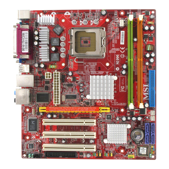
Page 13: Mainboard Layout
M S-7267 M ainboard Mainboard Layout 945GZM3 (MS-7267) Series v1.X Micro-ATX Mainboard... -
Page 14: Packing Checklist
Getting Started Packing Checklist MSI Driver/Utility CD SATA Cable MSI motherboard Standard Cable for Standard Cable for Power Cable Floppy Disk IDE Devices USB Bracket (Optional) User’s Guide Back IO Shield * The pictures are for reference only and may vary from the packing contents of the... -
Page 15: Msi Special Feature
M S-7267 M ainboard MSI Special Feature PC Alert™ 4 The PC Alert 4 is a utility you can find in the CD-ROM disk. The utility is just like your PC doctor that can detect the following PC hardware status during real time operation: ö... -
Page 16: Live Update
Live Update 3” icon (as shown on the right) will appear on the screen. Double click the “MSI Live Update 3” icon, and the following screen will appear: Several buttons are placed on the left column of the screen. Click the desired button to start the update process. -
Page 17: Chapter 2. Hardware Setup
Hardware Setup Chapter 2 Hardware Setup This chapter provides you with the information about hardware setup procedures. While doing the installation, be careful in holding the components and follow the installation procedures. For some components, if you install in the wrong orientation, the components will not work properly. -
Page 18: Quick Components Guide
M S-7267 M ainboard Quick Components Guide ATX1, p.2-9 DIMM1/2, p.2-7 JCI1, p2-15 CPU, p.2-3 CPUFAN1, JPW1, p2-15 JCOM1, p.2-9 p.2-19 Back Panel, p.2-11 I DE 1 , JIR1, p.2-13 p.2-19 PCIE_X16, SYSFAN1, p.2-21 p.2-15 PWRFAN1, PCI 1~3, p.2-15 p.2-22 SATA1~4, p.2-14 JAUD1,... -
Page 19: Cpu (Central Processing Unit)
CPU socket called LGA775. When you are installing the CPU, make sure to install the cooler to prevent overheating. If you do not have the CPU cooler, contact your dealer to purchase and install them before turning on the computer. For the latest information about CPU, please visit http://www.msi.com.tw/program/ products/mainboard/mbd/pro_mbd_cpu_support.php. Important 1. -
Page 20: Cpu & Cooler Installation
M S-7267 M ainboard CPU & Cooler Installation W hen you are installing the CPU, make sure the CPU has a cooler attached on the top to prevent overheating. If you do not have the cooler, contact your dealer to purchase and install them before turning on the computer. Meanwhile, do not forget to apply some silicon heat transfer compound on CPU before installing the heat sink/ cooler fan for better heat dispersion. - Page 21 Hardware Setup 5. Lift the load lever up and open the 6. After confirming the CPU direction load plate. for correct mating, put down the CPU in the socket housing frame. Be sure to grasp on the edge of the CPU base. Note that the align- ment keys are matched.
- Page 22 M S-7267 M ainboard 9. Press down the load lever lightly 10. Align the holes on the mainboard onto the load plate, and then se- with the heatsink. Push down the cure the lever with the hook under c ooler u nti l i ts f ou r c lip s g et retention tab.
-
Page 23: Memory
Hardware Setup Memory The mainboard provides two 240-pin non-ECC DDRII DIMMs and supports dual- channel technology up to 2GB system memory. For more information on compatible components, please visit http://www.msi.com.tw/ program/products/mainboard/mbd/pro_mbd_trp_list.php. DDRII 240-pin, 1.8V 64x2=128 pin 56x2=112 pin Dual-Channel: Channel A in GREEN; Channel B in ORANGE... -
Page 24: Installing Ddr/Ddrii Modules
M S-7267 M ainboard Installing DDRII Modules 1. The memory module has only one notch on the center and will only fit in the right orientation. 2. Insert the DIMM memory module vertically into the DIMM slot. Then push it in until the golden finger on the memory module is deeply inserted in the socket. -
Page 25: Power Supply
Hardware Setup Power Supply ATX 24-Pin Power Connector: ATX1 This connector allows you to connect an ATX 24-pin power supply. To connect the ATX 24-pin power supply, make sure the plug of the pin 13 power supply is inserted in the proper orientation and the pins are aligned. -
Page 26: Important Notification About Power Issue
M S-7267 M ainboard Important Notification about Power Issue NForce chipset is very sensitive to ESD (Electrostatic Discharge), therefore this issue mostly happens while the users intensively swap memory modules under S5 (power-off) states, and the power code is plugged while installing modules. Due to several pins are very sensitive to ESD, so this kind of memory-replacement actions might cause system chipset unable to boot. -
Page 27: Back Panel
Hardware Setup Back Panel RS-Out L-In Parallel M ou se CS-Out L-Out SPDIF Keyboard Serial Port VGA Port USB Ports M ouse/Keyboard Connector The standard PS/2 mouse/keyboard DIN connector is for a PS/2 mouse/keyboard. ® ® Parallel Port Connector A parallel port is a standard printer port that supports Enhanced Parallel Port (EPP) and Extended Capabilities Parallel Port (ECP) mode. - Page 28 M S-7267 M ainboard Audio Port Connectors These audio connectors are used for audio devices. You can differentiate the color of the audio jacks for different audio sound effects. Green audio jack - Line Out, is a connector for speakers or headphones. Blue audio jack - Line In / Side-Surround Out in 7.1 channel mode, is used f or external CD player, tapeplayer or other audio devices.
-
Page 29: Connectors
Hardware Setup Connectors Floppy Disk Drive Connector: FDD1 This standard FDD connector supports 360K, 720K, 1.2M, 1.44M and 2.88M floppy disk types. FDD1 Hard Disk Connector: IDE1 The mainboard provides a one-channel Ultra ATA 100 bus Master IDE controller that supports PIO mode 0~4, Bus Master, and Ultra DMA 66/100 function. -
Page 30: Serial Ataii Connectors: Sata1~Sata4
M S-7267 M ainboard Serial ATAII Connectors: SATA1~SATA4 SATA1~SATA4 are high-speed Serial ATA interface ports. Each supports serial ATA data rates of 300MB/s. Both connectors are fully compliant with Serial ATA 2.0 specifications. Each Serial ATA connector can connect to 1 hard disk device. SATA4 SATA3 SATA1~ SATA4 Pin Definition... -
Page 31: Fan Power Connectors: Cpufan1, Sysfan1, Pwrfan1
Hardware Setup Fan Power Connectors: CPUFAN1, SYSFAN1, PWRFAN1 The fan power connectors support system cooling fan with +12V. W hen connecting the wire to the connectors, always take note that the red wire is the positive and should be connected to the +12V, the black wire is Ground and should be connected to GND. -
Page 32: Cd-In Connector: Cd_In1
M S-7267 M ainboard CD-In Connector: CD_IN1 This connector is provided for CD-ROM audio. CD_IN1 Front Panel Connectors: JFP1/JFP2 The mainboard provides two front panel connectors for electrical connection to the front panel switches and LEDs. The JFP1 is compliant with Intel Front Panel I/O ®... -
Page 33: Front Panel Audio Connector: Jaud1
Hardware Setup Front Panel Audio Connector: JAUD1 The JAUD1 front panel audio connector allows you to connect the front panel audio and is compliant with Intel Front Panel I/O Connectivity Design Guide. ® JAUD1 JAUD1 Pin Definition SIGNAL DESCRIPTION AUD_MIC Front panel microphone input signal AUD_GND Ground used by analog audio circuits... -
Page 34: Front Usb Connectors: Jusb1, Jusb2
M S-7267 M ainboard Front USB Connectors: JUSB1, JUSB2 The mainboard provides two USB 2.0 pinheaders (optional USB 2.0 bracket available) that are compliant with Intel I/O Connectivity Design Guide. USB 2.0 technology ® increases data transfer rate up to a maximum throughput of 480Mbps, which is 40 times faster than USB 1.1, and is ideal for connecting high-speed USB interface peripherals such as USB HDD, digital cameras, M P3 players, printers, mo- dems and the like. -
Page 35: Irda Infrared Module Header: Jir1
Hardware Setup IrDA Infrared Module Header: JIR1 The connector allows you to connect to IrDA Infrared module. You must configure the setting through the BIOS setup to use the IR function. JIR1 is compliant with Intel ® Front Panel I/O Connectivity Design Guide. Pin Definition Signal IRRX... -
Page 36: Jumpers
M S-7267 M ainboard Jumpers Clear CMOS Jumper: JBAT1 There is a CMOS RAM onboard that has a power supply from external battery to keep the data of system configuration. With the CMOS RAM, the system can automatically boot OS every time it is turned on. If you want to clear the system configuration, set the JCMOS1 (Clear CMOS Jumper ) to clear data. -
Page 37: Slots
Hardware Setup Slots PCI (Peripheral Component Interconnect) Express Slots The PCI Express Lite slot (PCI Express x4) is a special design that supports only the following compatible PCI-E x16 VGA cards and runs at x4 speed. PCI Express x16 Slot Supported PCI Express VGA Card List for PCI Express Lite Slot (PCI Express x4) Model VGA Chip... -
Page 38: Pci (Peripheral Component Interconnect) Slots
M S-7267 M ainboard PCI (Peripheral Component Interconnect) Slots The PCI slots support LAN cards, SCSI cards, USB cards, and other add-on cards that comply with PCI specifications. At 32 bits and 33 MHz, it yields a throughput rate of 133 MBps. 32-bit PCI Slot Important When adding or removing expansion cards, make sure that you unplug the... -
Page 39: Chapter 3. Bios Setup
BIOS Setup Chapter 3 BIOS Setup This chapter provides information on the BIOS Setup program and allows you to configure the system for optimum use. You may need to run the Setup program when: ² An error message appears on the screen during the system booting up, and requests you to run SETUP. -
Page 40: Entering Setup
M S-7267 M ainboard Entering Setup Power on the computer and the system will start POST (Power On Self Test) process. W hen the message below appears on the screen, press <DEL> key to enter Setup. Press DEL to enter SETUP If the message disappears before you respond and you still wish to enter Setup, restart the system by turning it OFF and On or pressing the RESET button. -
Page 41: Control Keys
BIOS Setup Control Keys Move to the previous item < > Move to the next item < > Move to the item in the left hand < > Move to the item in the right hand < > Select the item <Enter>... -
Page 42: The Main Menu
M S-7267 M ainboard The Main Menu Standard CM OS Features Use this menu for basic system configurations, such as time, date etc. Advanced BIOS Features Use this menu to setup the items of special enhanced features. Advanced Chipset Setup Use this menu to change the values in the chipset registers and optimize your system’s performance. - Page 43 BIOS Setup Load Optimized Defaults Use this menu to load the default values set by the mainboard manufacturer specifi- cally for optimal performance of the mainboard. BIOS Setting Password Use this menu to set the password for BIOS. Save Changes & Exit Save changes to CMOS and exit setup.
-
Page 44: Standard Cmos Features
M S-7267 M ainboard Standard CMOS Features System Date (MM:DD:YY) This allows you to set the system to the date that you want (usually the current date). The format is <day><month> <date> <year>. Day of the week, from Sun to Sat, determined by BIOS. - Page 45 BIOS Setup Type This item allows you to select the hard disk type. Setting options: [Auto], [Disabled]. LBA/Large M ode This allows you to enable or disable the LBA Mode. Setting to Auto enables LBA mode if the device supports it and the devices is not already formatted with LBA mode disabled.
- Page 46 M S-7267 M ainboard Floppy A This item allows you to set the type of floppy drives installed. Available options: [None], [360K, 5.25 in.], [1.2M, 5.25 in.], [720K, 3.5 in.], [1.44M, 3.5 in.], [2.88M, 3.5 in.]. Halt On The setting determines whether the system will stop if an error is detected at boot. Available options are: [No Errors] The system doesn’t stop for any detected error.
-
Page 47: Advanced Bios Features
BIOS Setup Advanced BIOS Features Quick Boot Setting the item to [Enabled] allows the system to boot within 5 seconds since it will skip some check items. Setting options: [Enabled], [Disabled]. Boot to OS/2 This allows you to run the OS/2 operating system with DRAM larger than 64MB. - Page 48 M S-7267 M ainboard Max CPUID Value Limit: The Max CPUID Value Limit is designed to limit the listed speed of the processor to older operating systems. CPU TM function These settings specify the multiplier and VID values used by the processor in TM2 (Thermal Monitor 2) mode.
- Page 49 BIOS Setup M PS Configuration Press <Enter> to enter the sub-menu, and the following screen appears. MPS Revision This field allows you to select which MPS (Multi-Processor Specification) version to be used for the operating system. You need to select the MPS version supported by your operating system.
-
Page 50: Advanced Chipset Setup
M S-7267 M ainboard Advanced Chipset Setup Configure DRAM Timing by SPD Selects whether DRAM timing is controlled by the SPD (Serial Presence Detect) EEPROM on the DRAM module. Setting to [Auto By SPD] enables DRAM timings and the following related items to be determined by BIOS based on the configurations on the SPD. - Page 51 BIOS Setup purposes. The aperture is a portion of the PCI memory address range dedicated to graphics memory address space. Host cycles that hit the aperture range are for- warded to the AGP without any translation. VGA Share M emory size The system shares memory to the onboard VGA card.
-
Page 52: Integrated Peripherals
M S-7267 M ainboard Integrated Peripherals USB Functions This setting is used to enable/disable the onboard USB host controller. Setting options: [Disabled], [Enabled]. USB 2.0 Controller Set to [Enabled] if you need to use any USB 2.0 device in the operating system that does not support or have any USB 2.0 driver installed, such as DOS and SCO Unix. - Page 53 BIOS Setup Onboard LAN Option ROM The item enables or disables the initialization of the onboard LAN Boot ROMs during bootup. Selecting [Disabled] will speed up the boot process. Setting options: [Enabled], [Disabled]. IDE Devices Configuration Press <Enter> to enter the sub-menu and the following screen appears: PCI IDE BusMaster Set this option to [Enabled] to specify that the IDE controller on the PCI local bus has bus mastering capability.
- Page 54 M S-7267 M ainboard For the setting options of Configure SATA as, select [IDE] if you want to have SATA as IDE function. Audio Controller This item is used to enable or disable the onboard AC’97 (Audio Codec) controller. Selecting [Enabled] allows the mainboard to enable the onboard AC’97 controller. Disable the function if you want to use other controller cards to connect an audio device.
-
Page 55: Power Management Features
BIOS Setup Power Management Features ACPI Function This item is to activate the ACPI (Advanced Configuration and Power Management Interface) Function. If your operating system is ACPI-aware, such as Windows 98SE/ 2000/ME, select [Enabled]. Setting options: [Enabled] and [Disabled]. ACPI Standby State This item specifies the power saving modes for ACPI function. - Page 56 M S-7267 M ainboard Re-Call VGA BIOS from S3 W hen ACPI Standby State is set to [S3/STR], users can select the options in this field. Selecting [Yes] allows BIOS to call VGABIOS to initialize the VGA card when system wakes up (resumes) from S3 sleep state. The system resume time is short- ened when you disable the function, but system will need an AGP driver to initialize the VGA card.
- Page 57 BIOS Setup the system. Settings: [Disabled], [Specific Key] and [Any Key]. Specific Key for PowerOn If Keyboard Wakeup is set to [Specific Key], then you can set a password in the field for the PS/2 keyboard to power on the system. M ouse Wakeup The setting determines whether the system will be awakened from power sav- ing modes when the PS/2 mouse input signal is detected.
-
Page 58: Pnp/Pci Configurations
M S-7267 M ainboard PNP/PCI Configurations PCI Latency Timer This item controls how long each PCI device can hold the bus before another takes over. W hen set to higher values, every PCI device can conduct transactions for a longer time and thus improve the effective PCI bandwidth. For better PCI performance, you should set the item to higher values. - Page 59 BIOS Setup IRQ 3/4/5/7/9/10/11/14/15 These items specify the bus where the specified IRQ line is used. The settings determine if AMIBIOS should remove an IRQ from the pool of avail- able IRQs passed to devices that are configurable by the system BIOS. The available IRQ pool is determined by reading the ESCD NVRAM.
-
Page 60: H/W Monitor
M S-7267 M ainboard H/W Monitor CPU Shutdown Temp select If the CPU temperature reaches the limit preset in the next setting, the system will shutdown automatically. This helps you to prevent the CPU overheating problem. This item is available only when your OS supports this function, such as W indows ME/XP. Setting options: [Disabled], [80 C/176 F], [85... - Page 61 BIOS Setup System/CPU Temperature, System/CPU/Power FAN Speed, CPU Vcore, +12V, +5V, +3VSB, +3.3V These items display the current status of all of the monitored hardware devices/ components such as CPU voltages, temperatures and all fans’ speeds. 3-23...
-
Page 62: Cell_Menu
M S-7267 M ainboard Cell_Menu Spread spectrum W hen the motherboard’s clock generator pulses, the extreme values (spikes) of the pulses creates EMI (Electromagnetic Interference). The Spread Spectrum function reduces the EMI generated by modulating the pulses so that the spikes of the pulses are reduced to flatter curves. - Page 63 BIOS Setup Adjust CPU Ratio This item allows you to adjust the CPU ratio. Setting to [Startup] enables the CPU running at the fastest speed which is detected by system. Adjusted CPU Clock This item shows the current CPU clock. Adjusted M emory Frequency This item shows the current DDR memory frequency.
-
Page 64: Load Optimized Defaults
M S-7267 M ainboard Load Optimized Defaults The Optimized Defaults are the default values set by the mainboard manufacturer specifically for optimal performance of the mainboard. W hen you select Load Optimized Defaults, a message as below appears: Pressing Y loads the default factory settings for optimal system performance. 3-26... -
Page 65: Bios Setting Password
BIOS Setup BIOS Setting Password W hen you select this function, a message as below will appear on the screen: Type the password, up to 6 characters in length, and press <Enter>. The password typed now will replace any previously set password from CMOS memory. You will be prompted to confirm the password. -
Page 66: Appendix A Realtek Alc850 Audio
Realtek ALC850 Audio Appendix A Realtek ALC850 Audio The Realtek ALC850 supports 8-channel audio output, including 2 Front, 2 Rear, 1 Center and 1 Subwoofer channel. It enables connection to 2, 4, 6 or 8 speakers for better surround sound effect. This section tells you how to install and use 2-, 4-, 6- or 8-channel audio function on the board. -
Page 67: Installing The Audio Driver
M S-7267 M ainboard Installing the Audio Driver You need to install the driver for Realtek ALC850 codec to function properly before you can get access to 2-, 4-, 6- or 8- channel audio operations. Follow the procedures described below to install the drivers for different operating systems. Installation for Windows 98SE/ME/2000/XP For W indows 2000, you must install W indows... - Page 68 Realtek ALC850 Audio 3. Click Next to install the AC’97 Audio software. Click here 4. Click Finish to restart the system. S el ec t t hi s option Click here...
-
Page 69: Software Configuration
M S-7267 M ainboard Software Configuration After installing the audio driver, you are able to use the 2-, 4-, 6- or 8- channel audio feature now. Click the audio icon from the system tray at the lower-right corner of the screen to activate the AC97 Audio Configuration. It is also available to enable the audio driver by clicking the Sound Effect M anager from the Control Panel. -
Page 70: Sound Effect
Realtek ALC850 Audio Sound Effect Here you can select a sound effect you like from the Environment list. You may also edit the properties for an environment as you wish by clicking the “Edit” button, then just scroll the bar in the bottom for each property to adjust. - Page 71 M S-7267 M ainboard You may choose the provided sound effects, and the equalizer will adjust automatically. If you like, you may also load an equalizer setting or make an new equalizer setting to save as an new one by using the “Load EQ Setting” and “Save Preset” button, click “Reset EQ Setting”...
-
Page 72: Speaker Configuration
Realtek ALC850 Audio Speaker Configuration In this tab, you can easily configure your multi-channel audio function and speakers. 1. First you have to select the audio configuration below which is identical to the audio jack on your mainboard. In this model it uses Realtek ALC850 codec which supports 8-channel S/PDIF, therefore you should choose 8CH- S/PDIF (Optical &... - Page 73 M S-7267 M ainboard Select the speaker by clicking it to test its functionality. The one you select will light up and make testing sound. If any speaker fails to make sound, then check whether the cable is inserted firmly to the connector or replace the bad speak- ers with good ones.
-
Page 74: Hrtf Demo
Realtek ALC850 Audio HRTF Demo In this tab you may adjust your HRTF (Head Related Transfer Functions) 3D positional audio before playing 3D audio applications like gaming. You may also select different environment to choose the most suitable environment you like. -
Page 75: General
M S-7267 M ainboard General In this tab it provides some information about this AC97 Audio Configuration utility, including Audio Driver Version, DirectX Version, Audio Controller & AC97 Codec. You may also select the language of this utility by choosing from the Language list. Also there is a selection Show icon in system tray. -
Page 76: Spdif
Realtek ALC850 Audio SPDIF In this tab it provides options about SPDIF-Out for you to configure. † No Output: W ith this option, there is no S/PDIF output signal while playing analog and digital audio. † Output digital only: W ith this option, only digital audio will be allowed to play via SPDIF out while playing analog and digital audio. -
Page 77: Hardware Setup
M S-7267 M ainboard Hardware Setup Connecting the Speakers W hen you have set the Multi-Channel Audio Function mode properly in the software utility, connect your speakers to the correct phone jacks in accordance with the setting in software utility. n 2-Channel M ode for Stereo-Speaker Output Refer to the following diagram and caption for the function of each phone jack on the back panel when 2-Channel Mode is selected. - Page 78 Realtek ALC850 Audio n 4-Channel M ode for 4-Speaker Output Description: Connect two speakers to back panel’s Line Out connector and two speakers to the real-chan- 4-Channel Analog Audio Output nel Line Out connector. Line In Line Out (Front channels) Line Out (Rear channels) Line Out (Center and Subwoofer channel, but no functioning in this mode) Optical SPDIF Out...
- Page 79 M S-7267 M ainboard n 6-Channel M ode for 6-Speaker Output Description: Connect two speakers to back panel’s Line Out connector, two speakers to the rear-channel and two speakers to the cen- ter/subwoofer-channel Line Out 6-Channel Analog Audio Output connectors. Line In Line Out (Front channels) Line Out (Rear channels)
- Page 80 Realtek ALC850 Audio n 8-Channel M ode for 8-Speaker Output Description: Connect two speakers to back panel’s Line Out connector, two speakers to the rear-channel, two speakers to the c enter/ subwoofer-channel Line Out 8-Channel Analog Audio Output connectors, and two speakers to the side-channel Line Out Line Out (Side channels) connectors.