Table of Contents
Advertisement
Advertisement
Table of Contents

Related Manuals for MSI Hetis 945


Summary of Contents for MSI Hetis 945
- Page 1 Hetis 945 Hetis 945 Lite (MS-6410) User’s Guide G52-64101X2...
- Page 2 VOIR LA NOTICE D’INSTALLATION AVANT DE RACCORDER AU RESEAU. Micro-Star International Hetis 945 This device complies with Part 15 of the FCC Rules. Operation is subject to the following two conditions: (1) this device may not cause harmful interference, and (2) this device must accept any interference received, including interfer ence that may cause undesired operation.
-
Page 3: Revision History
Trademarks All trademarks are the properties of their respective owners. ® ® Intel and Pentium are registered trademarks of Intel Corporation. ® PS/2 and OS /2 are registered trademarks of International Business Machines Corporation. ® W indows 95/98/2000/NT/XP are registered trademarks of Microsoft Corporation. ®... -
Page 4: Safety Instructions
Safety Instructions Always read the safety instructions carefully. Keep this User’s Manual for future reference. Keep this equipment away from humidity. Lay this equipment on a reliable flat surface before setting it up. The openings on the enclosure are for air convection hence protects the equipment from overheating. - Page 5 Warning: 1. For every changes in powercordˇ¦s usage, please use an approved power cord with condition greater or equal to H05VV-F,3G , 0.75mm 2. Internal part is hazardous moving parts, please keep fingers and other body parts away. 3. For pluggable equipment, the socket-outlet shall be installed near the equipment and shall be easily accessible.
- Page 6 WEEE Statement...
- Page 8 viii...
-
Page 9: Table Of Contents
CONTENTS Chapter 1. Getting Started..................1-1 1.1 System Specifications................1-2 1.2 System Configuration................1-4 1.3 Thermal Solution...................1-10 Chapter 2. Introducing Mainboard..............2-1 2.1 Mainboard Layout..................2-2 2.2 CPU......................2-4 Introduction to LGA 775 CPU..............2-4 CPU & Cooler Installation..............2-5 2.3 Memory....................2-8 Introduction to DDR2 SDRAM...............2-8 DIMM Module Combination..............2-9 Installing DDR2 Modules..............2-9 2.4 Power Supply..................2-10 ATX 20-Pin Power Connector: ATX1..........2-10... - Page 10 On-Board RCA out Connector: J2 (Standard only)......2-21 Internal Speaker Connector: CON1............2-21 2.8 Jumper....................2-22 Clear CMOS Jumper: JBAT1...............2-22 2.9 Slot.......................2-23 PCI Express Slot: PCIE_1 (For Riser Card Use Only)......2-23 Chapter 3. System Assembly................3-1 3.1 Overview....................3-2 Installation Tools...................3-2 Sc rews....................3-2 Checking the Items................3-3 3.2 Installation Procedures................3-4 1.
- Page 11 Chapter 5. Introduction to Realtek ALC888............5-1 Installing the Realtek HD Audio Driver............5-2 Installation for Windows 2000/XP..............5-2 Software Configuration................5-4 Sound Effect....................5-5 Audio IO......................5-6 Mixer......................5-9 Microphone....................5-12 3D Audio Demo...................5-13 Information....................5-14 Using 2-, 4-, 6- & 8- Channel Audio Function..........5-15...
-
Page 12: Chapter 1. Getting Started
Getting Started 1.1 All-in-one Feature Set 1.2 System Specifications 1.3 System Configuration... -
Page 13: System Specifications
® Core™ 2 Duo/ Pentium D/ Pentium 4/ Celeron Series processors in the LGA775 package. † ® Supports Intel Hyper-Threading Technology (For the latest information about CPU, please visit http://www.msi.com.tw/ program/products/slim_pc/slm/pro_slm_cpu_support.php) Chipset † ® Intel 945G/945GZ chipset - Supports FSB 1066/800/533MHz... - Page 14 Chapter 1 - Getting Started On-Board Peripherals † Front I/O - Audio Ports (Headphone-Out x 1, Mic-In x 1) - USB2.0 Ports x 2 - IEEE 1394 (4pins) x 1 (For Standard Version) † Rear I/O - PS/2 keyboard/Mouse x 2 - Serial Ports x 2 - VGA Port x 1 - Audio Ports (Line-In x 1, Line-Out x 1, Mic-In x 1, RS-Out x 1, C/S Out x 1, SS-Out...
-
Page 15: System Configuration
1.2 System Configuration Standard Version Front View 1. Mic-in (pink), 5. HDD LED Headphone-out (green) 6. Optical Drive Eject/Close Button 2. 2 x USB 2.0 Ports 7. Optical Drive (optional) 3. 4-pin IEEE 1394 Port 8. Card Reader Drive (optional) 4. -
Page 16: Rear View
Chapter 1 - Getting Started Rear View 1. Voltage Selector 12. Power On/Off Switch 2. Power Jack 13. Support Bracket Spring 3. Ventilation Hole 14. RJ-45 LAN Jack 4. 4 x USB 2.0 Ports 15. 6-pin IEEE 1394 Port 5. PS/2 Mouse 16. -
Page 17: Front View
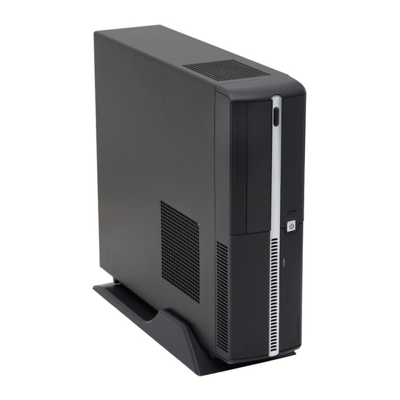
Lite Version Front View 1. Mic-in (pink), 4. HDD LED Headphone-out (green) 5. Optical Drive Eject/Close Button 2. 2 x USB 2.0 Ports 6. Optical Drive (optional) 3. Power Button & Power LED 7. Card Reader Drive (optional) - Page 18 Chapter 1 - Getting Started Rear View 1. Voltage Selector 10. Power On/Off Switch 2. Power Jack 11. Support Bracket Spring 3. Ventilation Hole 12. RJ-45 LAN Jack 4. 4 x USB 2.0 Ports 13. Expansion Slots 5. PS/2 Mouse 14.
- Page 19 Connecting to External Devices...
-
Page 20: Chassis Design
Chapter 1 - Getting Started Chassis Design † Dimension: 330mm (D) x 320mm (W) x 94mm (H) † Minimized screw structure † Detachable bay housing † Multiple ventilation holes 1. CPU Fan Ventilation Hole 4. Power Supply Ventilation Hole 2. System Ventilation Hole 5. -
Page 21: Thermal Solution
1.3 Thermal Solution To prevent the system from overheating, we have adopted a specially de- signed CPU cooler and multiple ventilation holes for better cooling effects. ® The specially designed CPU cooler supports Intel LGA775 processors. The following figures illustrate how the system fan effectively exhausts hot air through multiple ventilation holes. - Page 22 Chapter 1 - Getting Started Po w e r Po w e r Supply Fan Supply Sy stem Ventilation Hole Ventilation front panel Hole 1-11...
-
Page 23: System Air Flow Direction
System Air Flow Direction Po w e r Supply Po w e r Supply System Fan front panel After the installation is completed, please keep other objects away from the ventilation hole at least 2.5cm and above. Do not block the ventilation hole. 1-12... -
Page 24: Mainboard Layout
Mainboard Hardware 2.1 Mainboard Layout 2.2 CPU 2.3 Memory 2.4 Power Supply 2.5 Front Panel 2.6 Back Panel 2.7 Connectors 2.8 Jumper 2.9 Slots... - Page 25 2.1 Mainboard Layout MS-7231 (V2.X) Mainboard (Standard Version)
- Page 26 Chapter 2 - Mainboard Hardware MS-7231 (V2.X) Mainboard (Lite Version)
-
Page 27: Cpu
CPU cooler, contact your dealer to purchase and install them before turning on the computer. (For the latest information about CPU, please visit http://www. msi.com.tw/program/products/slim_pc/slm/pro_slm_cpu_support.php) MSI Reminds You... Overheating Overheating will seriously damage the CPU and system, always make sure the c ooling fan can work properly to protect the CPU from overheating. -
Page 28: Cpu & Cooler Installation
(if any). Please note not to to the center, as the arrows shown. touch the pins. MSI Reminds You... 1. Confirm if your CPU cooler is firmly installed before turning on your system. 2. Do not touch the CPU socket pins to avoid damaging. - Page 29 5. The CPU socket has a plastic cap on 6. Remove the cap from lever it to protect the contact from damage. h in g e s i d e ( as t h e ar row Before you have installed the CPU, shows).
- Page 30 Point 8 for details) again and on the mainboard. push the clip to lift up the CPU. MSI Reminds You... 1. Check the information in BIOS Chapter for the CPU temperature. 2. Whenever CPU is not installed, always protect your CPU socket pin with the plastic cap covered to avoid damaging.
-
Page 31: Memory
2.3 Memory The mainboard provides 2 slots for 240-pin DDR2 DIMM, which supports the memorysize up to 2GB.Since DDR2 modules are not interchangeable with DDR1 and the DDR2 standard is not backward compatible, you should always install DDR2 memory module in the DDR2 slot (DIMM1~DIMM2). Otherwise, you are not able to boot up your system and your mainboard might be damaged. -
Page 32: Dimm Module Combination
Chapter 2 - Mainboard Hardware DIMM Module Combination Install at least one DIMM module on the slots. Each DIMM slot supports up to a maximum size of 2GB. Users can install either single- or double-sided modules to meet their own needs. Please note that each DIMM can work respectively for single- channel DDR2, but there are some rules while using dual-channel DDR2. -
Page 33: Power Supply
ATX1 Pin Definition SIGNAL SIGNAL 3.3V 3.3V 3.3V -12V PS_ON PW_OK 5V_SB ATX1 JPW1 Pin Definition SIGNAL JPW1 MSI Reminds You... These two connectors connect to the power supply and have to work together to ensure stable operation of the mainboard. 2-10... -
Page 34: Front Panel
Chapter 2 - Mainboard Hardware 2.5 Front Panel IEEE 1394 4pins Headphone-out Mic-in USB Ports (For Standard Version) Audio Ports These audio ports allow you to connect front audio devices. Headphone-out MIC-in USB Ports The mainboard provides a UHCI (Universal Host Controller Interface) Universal Serial Bus root for attaching USB devices such as keyboard, mouse or other USB- compatible devices. -
Page 35: Rear Panel
2.6 Rear Panel RCA Out (For Stand ard Version) The Rear Panel provides the following connectors: Line-out IEEE 1394 6pins (For Standard Version) Line-in Serial Port LAN Jack VGA Port Mouse DVI Port Keyboard Serial Port MIC -in USB Ports (For Standard S-Video Out Version) -
Page 36: Audio Port Connectors
Chapter 2 - Mainboard Hardware Audio Port Connectors The left 3 audio jacks are for 2-channel mode for stereo speaker output: Line Out is a connector for Speakers or Headphones. Line In is used for external CD player, Tape player, or other audio devices. Mic is a connector for microphones. However, there is an advanced audio application provided by Realtek ALC888 to offer support for 7.1-channel audio operation and can turn rear audio connectors from 2-channel to 4-/5.1-/7.1- channel audio. -
Page 37: Digital Panel Connector (Dvi)(Standard Only)
Digital Panel Connector (DVI)(For Standard Version) The mainboard provides a DVI (Digital Visual Interface) connector which allows you to connect an LCD monitor. The DVI connector provides a high-speed digital interconnection between the computer and its display device. To connect a LCD monitor, simply plug your monitor cable into the DVI connector on the mainboard, and make sure that the other end of the cable is properly connected to your monitor. -
Page 38: Lan (Rj-45) Jack
Chapter 2 - Mainboard Hardware LAN (RJ-45) Jack The mainboard provides 1 standard RJ-45 jack for connection to single Local Area Network (LAN). This Giga-bit LAN enables data to be transferred at 1000, 100 or 10Mbps. You can connect a network cable to it. Giga-bit LAN Pin Definition SIGNAL DESCRIPTION... -
Page 39: Serial Ports
Serial Ports The mainboard offers two 9-pin male DIN connectors as serial ports. The ports are 16550A high speed communication ports that send/receive 16 bytes FIFOs. You can attach a serial mouse or other serial devices directly to the connectors. Serial Port Pin Definition 1 2 3 4 5 SIGNAL... -
Page 40: S-Video Out Connector (Standard Only)
Chapter 2 - Mainboard Hardware S-Video Out Connector (For Standard Version) The mainboard provides a S-Video Out connector for video-out function which allows you to output the image to a TV or video device. Simply plug one end of the S- Video cable into the S-Video Out connector on the mainboard, and the other end to the video input connector on your TV or video device. -
Page 41: Connectors
2.7 Connectors IDE Connector: IDE1 The mainboard has a 32-bit Enhanced PCI IDE and Ultra DMA 33/66/100 controller that provides PIO mode 0~4, Bus Master, and Ultra DMA/33/66/100 function. The connectors on the mainboard allows you to connect to the IDE devices: HDD & CD- ROM. -
Page 42: Serial Ata Connectors: Sata1/Sata2
CPU fan control. Sensor +12V +12V Sensor SYS_F1 CPU_F1 MSI Reminds You... 1. Always consult the vendors for proper CPU cooling fan. ® 2. Please refer to the recommended CPU fans at Intel official website. 2-19... -
Page 43: Front Panel Connectors: Jfp1
Front Panel Connectors: JFP1 The mainboard provides one front panel connector for you to connect to the ® front panel switches and LEDs. JFP1 is compliant with Intel Front Panel I/O Connectiv- ity Design Guide. Reset Power Switch Switch Power JFP1 JFP1 Pin Definition SIGNAL... -
Page 44: Internal Speaker Connector: Con1
Chapter 2 - Mainboard Hardware RCA out Connector: J3 (For Standard Version) The mainboard provides a TV-out connector for you to connect to a TV or video device. Internal Speaker Connector: CON1 This connector is used to connect the built-in speaker. CON1 2-21... -
Page 45: Jumper
JBAT1 Clear Data Keep Data MSI Reminds You... You can clear CMOS by shorting 2-3 pin while the system is off. Then return to 1-2 pin position. Avoid clearing the CMOS while the system is on; it will damage the mainboard. -
Page 46: Slot
Chapter 2 - Mainboard Hardware 2.9 Slot PCI Express Slot: PCIE_1 (For Riser Card Use Only) The mainboard provides one PCI Express slot. The PCI-E slot allows you to insert Riser Cards. The Riser Cards are included in the barebone. The Riser Cards allows you to insert two expansion card. You can insert any type of PCI cards to meet your needs. -
Page 47: Chapter 3. System Assembly
Chapter 3 - System Assembly System Assembly 3.1 Overview 3.2 Installation Procedures 1. Removing Cover 2. Installing HDD 3. Installing Optical Drive 4. Installing Card Reader (Optional) 5. Installing Memory Modules 6. Installing CPU 7. Installing CPU Coole 8. Restoring Chassis Cover & Installing Footstand... -
Page 48: Overview
3.1 Overview The built-in mainboard is designed for Hetis barebone only. Except the mainboard, the built-in components of the barebone include power supply. In this chapter we’ll show you how to install CPU, Card Reader, HDD, Optical Drives and CPU Cooler. Installation Tools Gloves Screw Driver... -
Page 49: Checking The Items
Chapter 3 - System Assembly Checking the Items Before assembling your system, please check the items listed below for basic system operation. The Footstand and the CPU cooler are included in the package, other items are optional. Footstand CPU Cooler Optical Drive (Optional) CPU (Optional) IDE or SATA HDD (Optional) -
Page 50: Installation Procedures
3.2 Installation Procedures 1. Removing Cover Unlock the two screws on the backplane with hands. Remove the chassis cover. Press the level on the support bracket spring to release it. Unlock the screw on the front panel to release the drive cage. -
Page 51: Installing Hdd
Chapter 3 - System Assembly 2. Installing HDD Lift the drive cage to slide aside. Pull the HDD tray forwards to re- move it from the chassis. Put the HDD in the HDD tray and use 4 screws to fix it on both sides. -
Page 52: Installing Optical Drive
3. Installing Optical Drive Pull the lock brackets outwards on the both sides to release. Insert the optical drive and push the lock brackets back to fix it. Connect the cable and the power cord to the optical drive, then restore the drive cage. -
Page 53: Installing Card Reader (Optional)
Chapter 3 - System Assembly 4. Installing Card Reader (Optional) Use the screwdriver to unlock the card reader cage. Insert the card reader into the cage with 15 degree angle. Insert the LED into the cage and lock the card reader with two screws. Restore the card reader back and connect the cable to the CR1 connector on the mainboard. -
Page 54: Installing Memory Modules
5. Installing Memory Modules Locate the DIMM slots. Insert the DIMM vertically into the slot. Note: The DIMM has only one notch on the center of module. It will only fit in the right direction. -
Page 55: Installing Cpu
Chapter 3 - System Assembly 6. Installing CPU Locate the CPU socket. Pull the lever away from the socket and raise it up, then lift up the cover. Put the CPU onto the socket. Note: Make sure the pins are com- pletely embedded into the socket. -
Page 56: Installing Cpu Cooler
7. Installing CPU Cooler Place the CPU cooler onto the CPU socket and secure the four screws. Connect the CPU cooler’s power cord to the connector on the mainboard. 3-10... -
Page 57: Restoring Chassis Cover
Chapter 3 - System Assembly 8. Restoring Chassis Cover Restore the support bracket. Restore the chassis cover. Lock the chassis cover with the s c rews . Put the PC on the footstand or lay on the rubber foots. Tower type Horizontal type 3-11... -
Page 58: Installing Footstand
9. Installing Footstand Lift up the PC and put the rubber feet into the pits on the footstand. Make sure the rubber feet to get stuck on the footstand. 3-12... -
Page 59: Chapter 4. Bios Setup
Chapter 4 - BIOS Setup BIOS Setup 4.1 Entering Setup 4.2 The Main Menu 4.3 Standard CMOS Features 4.4 Advanced BIOS Features 4.5 Advanced Chipset Features 4.6 Integrated Peripherals 4.7 Power Management Setup 4.8 System Information 4.9 H/W Monitor 4.10 Frequency / Voltage Control 4.11 Load Fail-Safe/Optimized Defaults 4.12 Set Supervisor/User Password... -
Page 60: Entering Setup
4.1 Entering Setup Power on the computer and the system will start POST (Power On Self Test) process. W hen the message below appears on the screen, press <DEL> key to enter Setup. DEL: Setup Menu F11: Boot Menu If the message disappears before you respond and you still wish to enter Setup, restart the system by turning it OFF and On or pressing the RESET button. -
Page 61: Control Keys
The preset Optimal Defaults of the BIOS setup program provide optimal performance settings for all devices and the system. MSI Reminds You... The items under each BIOS category described in this chapter are under continuous update for better system performance. Therefore, the description may be slightly different from the latest BIOS and should be held for reference only. -
Page 62: The Main Menu
4.2 The Main Menu Once you enter AWARD BIOS CMOS SETUP UTILITY, the Main Menu will appear on the screen. Use arrow keys to move among the items and press <Enter> to enter the sub-menu. Standard CMOS Features Use this menu for basic system configurations, such as time, date etc. Advanced BIOS Features Use this menu to setup the items of the special enhanced features. - Page 63 Chapter 4 - BIOS Setup System Information This entry shows your system summary. H/W Monitor This entry shows the status of your CPU, fan, warning for overall system status. Frequency / Voltage Control Use this menu to specify your settings for frequency/ voltage control. Load Fail-Safe Defaults Use this menu to load the default values set by the BIOS vendor for stable system performance.
-
Page 64: Standard Cmos Features
4.3 Standard CMOS Features The items in Standard CMOS Features Menu includes some basic setup items. Use the arrow keys to highlight the item and then use the <+> or <-> keys to select the value you want in each item. Date (MM:DD:YY) This allows you to set the system to the date that you want (usually the current date). - Page 65 Chapter 4 - BIOS Setup IDE Channel 0/1 Master/Slave Press <+> or <-> to select the hard disk drive type. The specification of hard d i s k drive will show up on the right hand according to your selection. Press <Enter> for the sub-menu of each item: IDE HDD Auto-Detection Press Enter to allow BIOS to auto-detect the type of the HDDs.
- Page 66 Halt On The setting determines whether the system will stop if an error is detected at boot. W hen the system stops for the errors preset, it will halt on for 15 seconds and then automatically resume its operation. Available options are: [All Errors] The system stops when any error is detected.
-
Page 67: Advanced Bios Features
Chapter 4 - BIOS Setup 4.4 Advanced BIOS Features CPU Feature Press <Enter> for the sub-menu of each item: C1E Function When The CPU ID>0F40 and is above 533MHz/2.8GHz or 800MHz/3.6GHz, you can enable C1E Support to lower the CPU power consumption while idle. Settings: [Auto], [Enabled] and [Disabled]. - Page 68 Please disable this item if your operating system doesn’t support HT Function, or unreliability and instability may occur. MSI Reminds You... Enabling the functionality of Hyper-Threading Technology for your com- puter system requires ALL of the following platform Components: ®...
- Page 69 These items allow you to set the sequence of boot devices where BIOS attempts to load the operating system. MSI Reminds You... Available settings for “First / Second / Third Boot Device” vary de- pending on the bootable devices you have installed. For example, if you did not install a floppy drive, the setting “Floppy”...
-
Page 70: Advanced Chipset Features
4.5 Advanced Chipset Features MSI Reminds You... Change these settings only if you are familiar with the chipset. DRAM Timing Selectable Selects whether DRAM timing is controlled by the SPD (Serial Presence Detect) EEPROM on the DRAM module. Setting to [By SPD] enables the following fields auto- matically to be determined by BIOS based on the configurations on the SPD. - Page 71 Chapter 4 - BIOS Setup DVMT M ode Use the field to select the mode of the digital monitor you use. Setting options: [Fixed Mode], [DVMT Mode], [Both]. DVM T / FIXED Memory Size This setting allows you to share the memory for the DVMT mode. Setting options: [64MB], [128MB].
-
Page 72: Integrated Peripherals
4.6 Integrated Peripherals OnChip IDE Device Press <Enter> for the sub-menu of each item: ***On-Chip Serial ATA Setting*** SATA Mode This setting is used to select the SATA mode. The setting are: [IDE] no AHCI, no RAID [RAID] RAID enabled [AHCI] AHCI enabled, no RAID Advanced Host Controller Interface (AHCI) includes a description of the hard-... - Page 73 Chapter 4 - BIOS Setup On-Chip Serial ATA This setting is used to specify the SATA controller. The settings are: [Disabled] Select this if you want to disable both SATA controller. [Auto] BIOS selects the mode automatically. [Combined Mode] You can use the IDE channels with S-ATA and P-ATA devices, and maximum of 2 devices in each channel are supported (maxinum of 4 devices).
- Page 74 Azalia/AC97 Audio Select This item allows you select Azalia Audio or AC97 Audio Setting options: [Enabled], [Disabled]. Onboard VIA6307 (IEEE1394) This setting is used to enable/disable the onboard VIA 1394 controller. Setting options: [Enabled], [Disabled]. SuperIO Device Press <Enter> for the sub-menu of each item: Onboard Serial Port 1/2 These items specify the base I/O port addresses of the onboard Serial Port 1 (COM A) / Serial Port 2 (COM B).
-
Page 75: Power Management Setup
Chapter 4 - BIOS Setup 4.7 Power Management Setup MSI Reminds You... S3-related functions described in this section are available only when your BIOS supports S3 sleep mode. ACPI Function This item is to activate the ACPI (Advanced Configuration and Power Management Interface) Function. - Page 76 Power On by Ring W hen it is set to [Enabled], the feature allows your system to be powered on by the serial Ring Indicator (RI) line. USB KB Wake-Up from S3 This setting allows you to enter “Any Key” (max. 8 numbers) to wake up the system from S3 state.
-
Page 77: System Information
Chapter 4 - BIOS Setup 4.8 System Information M achine M odel This item shows the name of Mainboard (read only). BIOS Version This item shows the BIOS version of your system (read only). CPU Type / CPU ID/uCodeID / CPU Frequency / CPU L2 Cache These items show the CPU related information of your system (read only). -
Page 78: H/W Monitor
4.9 H/W Monitor Current CPU/System Temperature, CPU/System FAN Speed, Vcore(V), VCC (V), +12V, +5V, VBAT(V) and 5VSB(V) These items display the current status of all of the monitored hardware devices/ components such as CPU voltages, temperatures and all fans’ speeds. Shutdown Temperature If the CPU temperature reaches the limit preset in this setting, the system will shotdown automatically. -
Page 79: Frequency / Voltage Control
EMI generated by modulating the pulses so that the spikes of the pulses are reduced to flatter curves. MSI Reminds You... 1. If you do not have any EMI problem, leave the setting at [Disabled] for optimal system stability and performance. But if you are plagued by EMI, select the value of Spread Spectrum for EMI reduction. -
Page 80: Load Fail-Safe/Optimized Defaults
4.11 Load-Fail Safe/Optimized Defaults The two options on the main menu allow users to restore all of the BIOS settings to the default Fail-Safe or Optimized values. The Optimized Defaults are the default values set by the mainboard manufacturer specifically for optimal performance of the mainboard. -
Page 81: Set Supervisor/User Password
Chapter 4 - BIOS Setup 4.12 Set Supervisor/User Password W hen you select this function, a message as below will appear on the screen: Type the password, up to six characters in length, and press <Enter>. The password typed now will replace any previously set password from CMOS memory. You will be prompted to confirm the password. -
Page 82: Chapter 5. Introduction To Realtek Alc888
Chapter 5 - Introduction to Realtek ALC 888 Introduction to Realtek ALC888 5.1 Installing the Realtek Audio Driver 5.2 Software Configuration 5.3 Using 2/4/6/8 Channel Audio Function... -
Page 83: Installation For Windows 2000/Xp
1. Insert the companion CD into the CD-ROM drive. The setup screen will auto- matically appear. 2. Click Realtek HD Audio Driver. Click here MSI Reminds You... The HD Audio Configuration software utility is under continuous update to enhance audio applications. Hence, the program screens shown here in this appendix may be slightly different from the latest software utility and shall be held for reference only. - Page 84 Chapter 5 - Introduction to Realtek ALC 888 3. Click Next to install the Realtek High Definition Audio Driver. Click here 4. Click Finish to restart the system. Select this option Click here...
-
Page 85: Software Configuration
5.2 Software Configuration After installing the audio driver, you are able to use the 2-, 4-, 6- or 8- channel audio feature now. Click the audio icon from the system tray at the lower-right corner of the screen to activate the HD Audio Configuration. It is also available to enable the audio driver by clicking the Azalia HD Sound Effect Manager from the Control Panel. -
Page 86: Sound Effect
Chapter 5 - Introduction to Realtek ALC 888 Sound Effect Here you can select a sound effect you like from the Environment list. Load EQ Setting Reset EQ Setting EQ Setting On/Off Save Preset Delete EQ Setting You may choose the provided sound effects, and the equalizer will adjust automatically. -
Page 87: Audioio
AudioIO In this tab, you can easily configure your multi-channel audio function and speakers. You can choose a desired multi-channel operation here. a. Headphone for the common headphone b. 2CH Speaker for Stereo-Speaker Output c. 4CH Speaker for 4-Speaker Output d. - Page 88 Chapter 5 - Introduction to Realtek ALC 888 Pop-screen check list 2CH Speakers configutaion - check the Front Speaker Out anyway. 4CH Speakers configuration - check the Front Speaker Out & Rear Speaker Out anyway. 6CH Speakers configuraion - check the Front Speaker Out / Rear Speaker Out &...
-
Page 89: Mixer
In the Mixer part, you may adjust the volumes of the rear and front panels individually. 1. Playback You can adjust the volume of the speakers that you pluged in. MSI Reminds You... Before set up, please make sure the playback devices are well plugged in the jacks. - Page 90 Mic in at front panel (Pink) from the scroll list after connecting microphone to the front audio panel. MSI Reminds You... Only the speakers that plugged into the Line-Out jack (the green ne) on the back panel will be functional when you intend to listen to the audio...
-
Page 91: Microphone
Microphone In this tab you may set the function of the microphone. Select the Noise Suppression to remove the possible noise during recording, or select Acoustic Echo Cancelltion to cancel the acoustic echo druing recording. 5-10... -
Page 92: Audio Demo
Chapter 5 - Introduction to Realtek ALC 888 3D Audio Demo In this tab you may adjust your 3D positional audio before playing 3D audio applications like gaming. You may also select different environment to choose the most suitable environment you like. 5-11... -
Page 93: Information
Information In this tab it provides some information about this HD Audio Configuration utility, including Audio Driver Version, DirectX Version, Audio Controller & Audio Codec. You may also select the language of this utility by choosing from the Language list. Also there is a selection Show icon in system tray. - Page 94 Chapter 5 - Introduction to Realtek ALC 888 5.3 Using 2/4/6/8 Channel Audio Function Connecting the Speakers W hen you have set the Multi-Channel Audio Function mode properly in the software utility, connect your speakers to the correct phone jacks in accordance with the setting in software utility.
- Page 95 n 4-Channel M ode for 4-Speaker Output Description: Connect two speakers to back panel’s Line Out connector and two speakers to the real-chan- 4-Channel Analog Audio Output nel Line Out connector. Line In Line Out (Front channels) Line Out (Rear channels) Line Out (Center and Subwoofer channel, but no functioning in this mode) Side Surround Out (Side channels, but no functioning in this mode) 5-14...
- Page 96 Chapter 5 - Introduction to Realtek ALC 888 n 6-Channel M ode for 6-Speaker Output Description: Connect two speakers to back panel’s Line Out connector, two speakers to the rear-channel 6-Channel Analog Audio Output and two speakers to the cen- ter/subwoofer-channel Line Out connectors.
- Page 97 n 8-Channel M ode for 8-Speaker Output Description: Connect two speakers to back panel’s Line Out connector, two speakers to the rear-channel, 8-Channel Analog Audio Output two speakers to the c enter/ subwoofer-channel Line Out connectors, and two speakers Line Out (Side channels) to the side-channel Line Out Line Out (Front channels) connectors.