
Related Manuals for Gigabyte GA-EX58-UD4P


Summary of Contents for Gigabyte GA-EX58-UD4P
- Page 1 GA-EX58-UD4P LGA1366 socket motherboard for Intel Core i7 processor family ® User's Manual Rev. 1003 12ME-EX58UD4-1003R...
-
Page 3: Identifying Your Motherboard Revision
GIGABYTE's prior written permission. Documentation Classifications In order to assist in the use of this product, GIGABYTE provides the following types of documentations: For quick set-up of the product, read the Quick Installation Guide included with the product. -
Page 4: Table Of Contents
Table of Contents Box Contents ......................... 6 Optional Items ......................... 6 GA-EX58-UD4P Motherboard Layout ................7 Block Diagram ........................ 8 Chapter 1 Hardware Installation ..................9 Installation Precautions ..................9 Product Specifications ..................10 Installing the CPU and CPU Cooler .............. 13 1-3-1 Installing the CPU .................... - Page 5 Configuring SATA Hard Drive(s) ..............89 5-1-1 Configuring Intel ICH10R SATA Controllers ............89 5-1-2 Configuring GIGABYTE SATA2 SATA Controller ..........95 5-1-3 Making a SATA RAID/AHCI Driver Diskette ........... 101 5-1-4 Installing the SATA RAID/AHCI Driver and Operating System ....102 Configuring Audio Input and Output ..............
-
Page 6: Box Contents
Box Contents GA-EX58-UD4P motherboard Motherboard driver disk User's Manual Quick Installation Guide One IDE cable and one floppy disk drive cable Four SATA 3Gb/s cables One SATA bracket I/O shield 2-Way SLI bridge connector 3-Way SLI bridge connector • The box contents above are for reference only and the actual items shall depend on product package you obtain. -
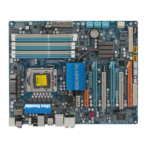
Page 7: Ga-Ex58-Ud4P Motherboard Layout
GA-EX58-UD4P Motherboard Layout CPU_FAN SYS_FAN3 KB_MS CPU Voltage L1/2/3 R_SPDIF LGA1366 ATX_12V_2X RST_SW V1394 CMOS_SW R_USB USB_LAN1 DDR Voltage LED DDR PHASE LED AUDIO F_AUDIO PCIEX1_1 (Note) Intel ® NB PHASE LED SYS_FAN1 RTL8111D PCIEX4_1 NB Voltage L1/2/3 SB Voltage L1/2/3... -
Page 8: Block Diagram
RJ45 1 PCI Express x1 Dual BIOS 8111D PCI CLK (33 MHz) 6 SATA 3Gb/s Intel ® PCI Express Bus ICH10R GIGABYTE 12 USB Ports SATA2 2 SATA 3Gb/s ATA-133/100/66/33 IDE Channel LPC Bus PCI Bus Floppy IT8720 TSB43AB23 CODEC... -
Page 9: Chapter 1 Hardware Installation
Chapter 1 Hardware Installation Installation Precautions The motherboard contains numerous delicate electronic circuits and components which can become damaged as a result of electrostatic discharge (ESD). Prior to installation, carefully read the user's manual and follow these procedures: Prior to installation, do not remove or break motherboard S/N (Serial Number) sticker or •... -
Page 10: Product Specifications
Product Specifications Support for an Intel Core i7 series processor in the LGA 1366 package ® (Go to GIGABYTE's website for the latest CPU support list.) L3 cache varies with CPU 4.8GT/s / 6.4GT/s Chipset North Bridge: Intel X58 Express Chipset ... - Page 11 Integrated in the South Bridge Up to 12 USB 2.0/1.1 ports (8 on the back panel, 4 via the USB brackets connected to the internal USB headers) Internal Connectors 1 x 24-pin ATX main power connector 1 x 8-pin ATX 12V power connector 1 x floppy disk drive connector ...
- Page 12 PCI Express graphics card, the PCIEX16_2 slot will operate at up to x8 mode. (Note 4) Whether the CPU/system fan speed control function is supported will depend on the CPU/ system cooler you install. (Note 5) Available functions in EasyTune may differ by motherboard model. GA-EX58-UD4P Motherboard - 12 -...
-
Page 13: Installing The Cpu And Cpu Cooler
Read the following guidelines before you begin to install the CPU: • Make sure that the motherboard supports the CPU. (Go to GIGABYTE's website for the latest CPU support list.) • Always turn off the computer and unplug the power cord from the power outlet before installing the CPU to prevent hardware damage. - Page 14 CPU is not alignment keys) and gently insert the CPU installed.) into position. Step 5: Once the CPU is properly inserted, replace the load plate and push the CPU socket lever back into its locked position. GA-EX58-UD4P Motherboard - 14 -...
-
Page 15: Installing The Cpu Cooler
1-3-2 Installing the CPU Cooler Follow the steps below to correctly install the CPU cooler on the motherboard. (The following procedure uses Intel boxed cooler as the example cooler.) ® Male Push Pin Direction of The Top of the Arrow Female Sign on the Push Pin... -
Page 16: Installing The Memory
• Make sure that the motherboard supports the memory. It is recommended that memory of the same capacity, brand, speed, and chips be used. (Go to GIGABYTE's website for the latest memory support list.) • Always turn off the computer and unplug the power cord from the power outlet before installing the memory to prevent hardware damage. -
Page 17: Installing A Memory
1-4-2 Installing a Memory Before installing a memory module , make sure to turn off the computer and unplug the power cord from the power outlet to prevent damage to the memory module. DDR3 and DDR2 DIMMs are not compatible to each other or DDR DIMMs. Be sure to install DDR3 DIMMs on this motherboard. -
Page 18: Installing An Expansion Card
• Removing the Card: Press the white latch at the end of the PCI Express slot to release the card and then pull the card straight up from the slot. GA-EX58-UD4P Motherboard - 18 -... -
Page 19: Setup Of Nvidia Sli (Scalable Link Interface)/Ati Crossfirex Configuration
Setup of NVIDIA SLI (Scalable Link Interface)/ATI CrossFireX Configuration The SLI and CrossFireX technologies offer blistering graphics performance with the ability to bridge two or three PCI Express graphics cards! This section provides instructions on configuring an SLI/ CrossFireX system. A. - Page 20 SLI gold edge connectors on top of the two graphics cards. Step 2: Connect power cables to the three graphics cards. Step 3: Plug the display cable into the graphics card on the PCIEX16_1 slot. GA-EX58-UD4P Motherboard - 20 -...
- Page 21 C. Configuring the Graphics Card Driver: To enable SLI function For 2-Way/3-Way SLI: After installing graphics card driver in the operating system, go to the NVIDIA Control Panel. Browse to the SLI and Physx configuration screen. Ensure SLI configuration and Physx are enabled.
-
Page 22: Installing The Sata Bracket
SATA device. For SATA device in external enclosure, you only need to connect the SATA signal cable. Before connecting the SATA signal cable, make sure to turn off the power of the external enclosure. GA-EX58-UD4P Motherboard - 22 -... -
Page 23: Back Panel Connectors
Back Panel Connectors CMOS PS/2 Keyboard and PS/2 Mouse Port Use the upper port (green) to connect a PS/2 mouse and the lower port (purple) to connect a PS/2 keyboard. Optical S/PDIF Out Connector This connector provides digital audio out to an external audio system that supports digital optical audio. - Page 24 Only microphones still MUST be con- nected to the default Mic in jack ( ). Refer to the instructions on setting up a 2/4/5.1/ 7.1-channel audio configuration in Chapter 5, "Configuring 2/4/5.1/7.1-Channel Audio." GA-EX58-UD4P Motherboard - 24 -...
-
Page 25: Onboard Leds And Switches
Onboard LEDs and Switches Overvoltage LEDs This motherboard contains 4 sets of overvoltage LEDs which indicate the overvoltage level of the CPU, memory, North Bridge, and South Bridge. CPU (CPU Voltage) Memory (DDR Voltage) Off: Normal condition Off: Normal condition L1: Level 1 (Slight, green) L1: Level 1 (Slight, green) L2: Level 2 (Moderate, yellow) -
Page 26: Quick Switches
This motherboard has 3 quick switches: power switch, reset switch and clearing CMOS switch, allowing users to quickly turn on/off or reset the system or clear the CMOS values. PW_SW: Power switch RST_SW: Reset switch CMOS_SW: Clearing CMOS switch GA-EX58-UD4P Motherboard - 26 -... -
Page 27: Internal Connectors
1-10 Internal Connectors ATX_12V_2X F_AUDIO CD_IN CPU_FAN SPDIF_I SYS_FAN1/2/3 SPDIF_O PWR_FAN F_USB1/F_USB2 NB_FAN F1_1394/F2_1394 CLR_CMOS SATA2_0/1/2/3/4/5 GSATA2_0/1 PHASE_LED PWR_LED NB PHASE LED F_PANEL DDR PHASE LED Read the following guidelines before connecting external devices: • First make sure your devices are compliant with the connectors you wish to connect. •... - Page 28 3.3V -12V PS_ON(soft On/Off) Power Good 5V SB(stand by +5V) +12V +12V (Only for 2x12 pin ATX) +5V (Only for 2x12 pin ATX) 3.3V (Only for 2x12 pin ATX) GND (Only for 2x12 pin ATX) GA-EX58-UD4P Motherboard - 28 -...
- Page 29 3/4/5) CPU_FAN / SYS_FAN1 / SYS_FAN2 / SYS_FAN3 / PWR_FAN (Fan Headers) The motherboard has a 4-pin CPU fan header (CPU_FAN), a 4-pin (SYS_FAN2) and two 3-pin (SYS_FAN1/SYS_FAN3) system fan headers, and a 3-pin power fan header (PWR_FAN). Most fan headers possess a foolproof insertion design.
- Page 30 IDE devices (for example, master or slave). (For information about configuring master/slave settings for the IDE devices, read the instructions from the device manufacturers.) GA-EX58-UD4P Motherboard - 30 -...
- Page 31 9) SATA2_0/1/2/3/4/5 (SATA 3Gb/s Connectors, Controlled by ICH10R, Blue) The SATA connectors conform to SATA 3Gb/s standard and are compatible with SATA 1.5Gb/s standard. Each SATA connector supports a single SATA device. The ICH10R controller supports RAID 0, RAID 1, RAID 5 and RAID 10. Refer to Chapter 5, "Configuring SATA Hard Drive(s)," for instructions on configuring a RAID array.
- Page 32 The SATA connectors conform to SATA 3Gb/s standard and are compatible with SATA 1.5Gb/s standard. Each SATA connector supports a single SATA device. The GIGABYTE SATA2 controller supports RAID 0, RAID 1 and JBOD. Refer to Chapter 5, "Configuring SATA Hard Drive(s)," for instructions on configuring a RAID array.
- Page 33 12) F_PANEL (Front Panel Header) Connect the power switch, reset switch, speaker and system status indicator on the chassis front panel to this header according to the pin assignments below. Note the positive and negative pins before connecting the cables. Message/Power/ Power Sleep LED...
- Page 34 14) CD_IN (CD In Connector, Black) You may connect the audio cable that came with your optical drive to the header. Pin No. Definition CD-L CD-R GA-EX58-UD4P Motherboard - 34 -...
- Page 35 15) SPDIF_I (S/PDIF In Header, Red) This header supports digital S/PDIF in and can connect to an audio device that supports digital audio out via an optional S/PDIF in cable. For purchasing the optional S/PDIF in cable, please contact the local dealer. Pin No.
- Page 36 • To connect an IEEE 1394a device, attach one end of the device cable to your computer and then attach the other end of the cable to the IEEE 1394a device. Ensure that the cable is securely connected. GA-EX58-UD4P Motherboard - 36 -...
- Page 37 19) CI (Chassis Intrusion Header) This motherboard provides a chassis detection feature that detects if the chassis cover has been removed. This function requires a chassis with chassis intrusion detection design. Pin No. Definition Signal 20) CLR_CMOS (Clearing CMOS Jumper) Use this jumper to clear the CMOS values (e.g.
- Page 38 The number of lighted LEDs indicates the CPU loading. The higher the CPU loading, the more the number of lighted LEDs. To enable the Phase LED display function, please first enable Dynamic Energy Saver Advanced. Refer to Chapter 4, "Dynamic Energy Saver Advanced," for more details. GA-EX58-UD4P Motherboard - 38 -...
- Page 39 23) NB PHASE LED The number of lighted LEDs indicates the North Bridge loading. The higher the North Bridge loading, the more the number of lighted LEDs. 24) DDR PHASE LED The number of lighted LEDs indicates the memory loading. The higher the memory loading, the more the number of lighted LEDs.
- Page 40 GA-EX58-UD4P Motherboard - 40 -...
-
Page 41: Chapter 2 Bios Setup
To see more advanced BIOS Setup menu options, you can press <Ctrl> + <F1> in the main menu of the BIOS Setup program. To upgrade the BIOS, use either the GIGABYTE Q-Flash or @BIOS utility. Q-Flash allows the user to quickly and easily upgrade or back up BIOS without entering the •... -
Page 42: Startup Screen
BIOS Setup settings. You can access Boot Menu again to change the first boot device setting as needed. <End>: Q-FLASH Press the <End> key to access the Q-Flash utility directly without having to enter BIOS Setup first. GA-EX58-UD4P Motherboard - 42 -... -
Page 43: The Main Menu
The Main Menu Once you enter the BIOS Setup program, the Main Menu (as shown below) appears on the screen. Use arrow keys to move among the items and press <Enter> to accept or enter a sub-menu. (Sample BIOS Version: F1B) CMOS Setup Utility-Copyright (C) 1984-2008 Award Software ... - Page 44 Abandon all changes and the previous settings remain in effect. Pressing <Y> to the confirmation message will exit BIOS Setup. (Pressing <Esc> can also carry out this task.) Security Chip Configuration Use this menu to configure the TPM function. GA-EX58-UD4P Motherboard - 44 -...
-
Page 45: Mb Intelligent Tweaker(M.i.t.)
MB Intelligent Tweaker(M.I.T.) CMOS Setup Utility-Copyright (C) 1984-2008 Award Software MB Intelligent Tweaker(M.I.T.) (Note 1) CPU Clock Ratio [22X] Item Help CPU Frequency 2.93GHz(133x22) Menu Level Advanced CPU Features [Press Enter] QPI Link Speed [Auto] QPI Link Speed 4.8GHz ... -
Page 46: Cpu Frequency
The C3/C6/C7 state is a more enhanced power-saving state than C1. (Default: Disabled) (Note) This item is present only if you install a CPU that supports this feature. For more information about Intel CPUs' unique features, please visit Intel's website. GA-EX58-UD4P Motherboard - 46 -... - Page 47 CPU Thermal Monitor (Note) Enables or disables Intel CPU Thermal Monitor function, a CPU overheating protection function. ® When enabled, the CPU core frequency and voltage will be reduced when the CPU is overheated. (Default: Enabled) CPU EIST Function (Note) Enables or disables Enhanced Intel SpeedStep Technology (EIST).
- Page 48 Increases CPU frequency by 17% or 19% depending on CPU loading. Warning: Before using C.I.A.2, please first verify the overclocking capability of your CPU. As stability is highly dependent on system components, when system instability occurs after overclocking, lower the overclocking ratio. GA-EX58-UD4P Motherboard - 48 -...
- Page 49 >>>>> Advanced Clock Control CPU Clock Drive Allows you to adjust the amplitude of the CPU and North Bridge clock. Options are: 700mV, 800mV (default), 900mV, 1000mV. PCI Express Clock Drive Allows you to adjust the amplitude of the PCI Express and North Bridge clock. Options are: 700mV, 800mV, 900mV (default), 1000mV.
- Page 50 F6: Fail-Safe Defaults F7: Optimized Defaults >>>>> Channel A/B/C Standard Timing Control CAS Latency Time Options are: Auto (default), 6~16. tRCD Options are: Auto (default), 1~15. Options are: Auto (default), 1~15. tRAS Options are: Auto (default), 1~63. GA-EX58-UD4P Motherboard - 50 -...
- Page 51 >>>>> Channel A/B/C Advanced Timing Control Options are: Auto (default), 1~63. tRRD Options are: Auto (default), 1~15. tWTR Options are: Auto (default), 1~31. Options are: Auto (default), 1~31. tRFC Options are: Auto (default), 1~255. tRTP Options are: Auto (default), 1~15. tFAW Options are: Auto (default), 1~63.
- Page 52 Options are: Auto (default), 1~2. >>>>> Channel A/B/C Writes Followed by Writes Different DIMMs Options are: Auto (default), 1~8. Different Ranks Options are: Auto (default), 1~8. On The Same Rank Options are: Auto (default), 1~2. GA-EX58-UD4P Motherboard - 52 -...
-
Page 53: Cpu Vcore
******* Advanced Voltage Control ******* CMOS Setup Utility-Copyright (C) 1984-2008 Award Software Advanced Voltage Control Voltage Types Normal Current Item Help ------------------------------------------------------------------ Menu Level >>> CPU Load-Line Calibration [Disabled] CPU Vcore 1.12500V [Auto] QPI/Vtt Voltage 1.200V [Auto] CPU PLL 1.800V [Auto] >>>... - Page 54 Ch-B Data VRef. The default is Auto. Ch-C Data VRef. The default is Auto. Ch-A Address VRef. The default is Auto. Ch-B Address VRef. The default is Auto. Ch-C Address VRef. The default is Auto. GA-EX58-UD4P Motherboard - 54 -...
-
Page 55: Standard Cmos Features
Standard CMOS Features CMOS Setup Utility-Copyright (C) 1984-2008 Award Software Standard CMOS Features Date (mm:dd:yy) Mon, May 26 2008 Item Help Time (hh:mm:ss) 18:25:04 Menu Level IDE Channel 0 Master [None] IDE Channel 0 Slave [None] IDE Channel 1 Master [None] ... - Page 56 Base Memory Also called conventional memory. Typically, 640 KB will be reserved for the MS-DOS operating system. Extended Memory The amount of extended memory. Total Memory The total amount of memory installed on the system. GA-EX58-UD4P Motherboard - 56 -...
-
Page 57: Advanced Bios Features
Advanced BIOS Features CMOS Setup Utility-Copyright (C) 1984-2008 Award Software Advanced BIOS Features Hard Disk Boot Priority [Press Enter] Item Help First Boot Device [Floppy] Menu Level Second Boot Device [Hard Disk] Third Boot Device [CDROM] Password Check [Setup] HDD S.M.A.R.T. - Page 58 Allows you to set a delay time for the BIOS to initialize the hard drive as the system boots up. The adjustable range is from 0 to 15 seconds. (Default: 0) Full Screen LOGO Show Allows you to determine whether to display the GIGABYTE Logo at system startup. Disabled displays normal POST message. (Default: Enabled) Init Display First Specifies the first initiation of the monitor display from the installed PCI graphics card or PCI Express graphics card.
-
Page 59: Integrated Peripherals
Integrated Peripherals CMOS Setup Utility-Copyright (C) 1984-2008 Award Software Integrated Peripherals SATA RAID/AHCI Mode [Disabled] Item Help SATA Port0-3 Native Mode [Disabled] Menu Level USB 1.0 Controller [Enabled] USB 2.0 Controller [Enabled] USB Keyboard Function [Disabled] USB Mouse Function [Disabled] USB Storage Function [Enabled] Azalia Codec... -
Page 60: Usb Storage Function
If no cable problem is detected on the LAN cable connected to a Gigabit hub or a 10/100 Mbps hub, the following message will appear: Start detecting at Port..Link Detected --> 100Mbps Cable Length= 30m GA-EX58-UD4P Motherboard - 60 -... - Page 61 (Default: Enabled) Onboard SATA/IDE Ctrl Mode (GIGABYTE SATA2 Chip) Enables or disables RAID for the SATA controller integrated in the GIGABYTE SATA2 chip or configures the SATA controller to AHCI mode. Disables RAID for the SATA controller and configures the SATA controller to PATA mode.
-
Page 62: Power Management Setup
Power On by Ring Allows the system to be awakened from an ACPI sleep state by a wake-up signal from a modem that supports wake-up function. (Default: Enabled) (Note) Supported on Windows Vista operating system only. ® ® GA-EX58-UD4P Motherboard - 62 -... - Page 63 Resume by Alarm Determines whether to power on the system at a desired time. (Default: Disabled) If enabled, set the date and time as following: Date(of Month) Alarm: Turn on the system at a specific time on each day or on a specific day in a month.
-
Page 64: Pc Health Status
F, 90 C/194 CPU/SYSTEM/POWER FAN Fail Warning Allows the system to emit warning sound if the CPU/system/power fan is not connected or fails. Check the fan condition or fan connection when this occurs. (Default: Disabled) GA-EX58-UD4P Motherboard - 64 -... - Page 65 CPU Smart FAN Control Enables or disables the CPU fan speed control function. Enabled allows the CPU fan to run at different speed according to the CPU temperature. You can adjust the fan speed with EasyTune based on system requirements. If disabled, CPU fan runs at full speed. (Default: Enabled) CPU Smart FAN Mode Specifies how to control CPU fan speed.
-
Page 66: Load Fail-Safe Defaults
Press <Enter> on this item and then press the <Y> key to load the optimal BIOS default settings. The BIOS defaults settings helps the system to operate in optimum state. Always load the Optimized defaults after updating the BIOS or after clearing the CMOS values. GA-EX58-UD4P Motherboard - 66 -... -
Page 67: Set Supervisor/User Password
2-11 Set Supervisor/User Password CMOS Setup Utility-Copyright (C) 1984-2008 Award Software MB Intelligent Tweaker(M.I.T.) Load Optimized Defaults Standard CMOS Features Set Supervisor Password Advanced BIOS Features Set User Password Integrated Peripherals Save & Exit Setup Power Management Setup Exit Without Saving Enter Password:... -
Page 68: Save & Exit Setup
Press <Enter> on this item and press the <Y> key. This exits the BIOS Setup without saving the changes made in BIOS Setup to the CMOS. Press <N> or <Esc> to return to the BIOS Setup Main Menu. GA-EX58-UD4P Motherboard - 68 -... -
Page 69: Security Chip Configuration
2-14 Security Chip Configuration CMOS Setup Utility-Copyright (C) 1984-2008 Award Software Security Chip Configuration Security Chip [Disabled] Item Help Menu Level Security Chip State Disabled/Deactivated : Move Enter: Select +/-/PU/PD: Value F10: Save ESC: Exit F1: General Help F5: Previous Values F6: Fail-Safe Defaults F7: Optimized Defaults Security Chip... - Page 70 GA-EX58-UD4P Motherboard - 70 -...
-
Page 71: Chapter 3 Drivers Installation
Chapter 3 Drivers Installation • Before installing the drivers, first install the operating system. • After installing the operating system, insert the motherboard driver disk into your optical drive. The driver Autorun screen is automatically displayed which looks like that shown in the screen shot below. -
Page 72: Application Software
Application Software This page displays all the utilities and applications that GIGABYTE develops and some free software. You can click the Install button on the right of an item to install it. Technical Manuals This page provides GIGABYTE's application guides, content descriptions for this driver disk, and the motherboard manuals. -
Page 73: Contact
Contact For the detailed contact information of the GIGABYTE Taiwan headquarter or worldwide branch offices, click the URL on this page to link to the GIGABYTE Website. System This page provides the basic system information. - 73 - Drivers Installation... -
Page 74: Download Center
Download Center To update the BIOS, drivers, or applications, click the Download Center button to link to the GIGABYTE Web site. The latest version of the BIOS, drivers, or applications will be displayed. GA-EX58-UD4P Motherboard - 74 -... -
Page 75: Chapter 4 Unique Features
Chapter 4 Unique Features Xpress Recovery2 Xpress Recovery2 is a utility that allows you to quickly compress and back up your system data and perform restoration of it. Supporting NTFS, FAT32, and FAT16 file systems, Xpress Recovery2 can back up data on PATA and SATA hard drives and restore it. Before You Begin: •... - Page 76 Xpress Recovery2 will automatically create a new partition to store the backup image file. Step 1: Step 2: Select BACKUP to start backing up your hard When finished, go to Disk Management to drive data. check disk allocation. GA-EX58-UD4P Motherboard - 76 -...
- Page 77 D. Using the Restore Function in Xpress Recovery2 Select RESTORE to restore the backup to your hard drive in case the system breaks down. The RESTORE option will not be present if no backup is created before. E. Removing the Backup Step 1: Step 2: If you wish to remove the backup file, select...
-
Page 78: Bios Update Utilities
4-2-1 Updating the BIOS with the Q-Flash Utility A. Before You Begin: 1. From GIGABYTE's website, download the latest compressed BIOS update file that matches your motherboard model. 2. Extract the file and save the new BIOS file (e.g. ex58ud4p.f1) to your floppy disk, USB flash drive, or hard drive. - Page 79 B. Updating the BIOS When updating the BIOS, choose the location where the BIOS file is saved. The follow procedure assumes that you save the BIOS file to a floppy disk. Step 1: 1. Insert the floppy disk containing the BIOS file into the floppy disk drive. In the main menu of Q-Flash, use the up or down arrow key to select Update BIOS from Drive and press <Enter>.
- Page 80 Load Optimized Defaults Press <Y> to load BIOS defaults Step 6: Select Save & Exit Setup and then press <Y> to save settings to CMOS and exit BIOS Setup. The procedure is complete after the system restarts. GA-EX58-UD4P Motherboard - 80 -...
-
Page 81: Updating The Bios With The @Bios Utility
BIOS or a system that is unable to start. 3. Do not use the G.O.M. (GIGABYTE Online Management) function when using @BIOS. 4. GIGABYTE product warranty does not cover any BIOS damage or system failure resulting from an inadequate BIOS flashing. -
Page 82: Easytune 6
EasyTune 6 GIGABYTE's EasyTune 6 is a simple and easy-to-use interface that allows users to fine-tune their system settings or do overclock/overvoltage in Windows environment. The user-friendly EasyTune 6 interface also includes tabbed pages for CPU and memory information, lettings users read their system- related information without the need to install additional software. -
Page 83: Dynamic Energy Saver Advanced
The Dynamic Energy Saver Advanced Interface A. Meter Mode In Meter Mode, GIGABYTE Dynamic Energy Saver Advanced shows how much power they have saved in a set period of time. Meter Mode - Button Information Table... - Page 84 (Note 4) The total amount of power saved will be recorded until re-activated when only the Dynamic Power Saver is under the enable status, and power savings meter is unable to reset to zero. (Note 5) Dynamic Energy Saver Meter will automatically reset when the total power saving reaches 99999999 Watts. GA-EX58-UD4P Motherboard - 84 -...
-
Page 85: Ultra Tpm
• Though the TPM delivers the latest data security technology, it does not guarantee data integrity or give hardware protection. GIGABYTE is not liable for loss of encrypted data as a result of hardware damage. A. Before installing Ultra TPM, follow the steps below in sequence: Step 1: Turn on your computer and enter the BIOS Setup program. -
Page 86: Q-Share
Q-Share, you are able to share your data with computers on the same network, making full use of Internet resources. Directions for using Q-Share After installing Q-Share from the motherboard driver disk, go to Start>All Programs>GIGABYTE> Q-Share.exe to launch the Q-Share tool. Find the Q-Share icon in your system tray and right-click on this icon to configure the data sharing settings. -
Page 87: Time Repair
Time Repair Based on the Microsoft Volume Shadow Copy Services technology, Time Repair allows you to quickly back up and restore your system data in the Windows Vista operating system. Time Repair supports NTFS file system and can restore system data on PATA and SATA hard drives. System Restore Choose a system restore point using the navigation bar on the right or at the bottom of the screen to view the system data backed up at different time. - Page 88 GA-EX58-UD4P Motherboard - 88 -...
-
Page 89: Chapter 5 Appendix
Chapter 5 Appendix Configuring SATA Hard Drive(s) To configure SATA hard drive(s), follow the steps below: A. Install SATA hard drive(s) in your computer. B. Configure SATA controller mode in BIOS Setup. C . Configure a RAID array in RAID BIOS. (Note 1) D. - Page 90 The BIOS Setup menus described in this section may differ from the exact settings for your motherboard. The actual BIOS Setup menu options you will see shall depend on the motherboard you have and the BIOS version. GA-EX58-UD4P Motherboard - 90 -...
-
Page 91: Create Raid Volume
C. Configuring a RAID array in RAID BIOS Enter the RAID BIOS setup utility to configure a RAID array. Skip this step and proceed with the installation of Windows operating system for a non-RAID configuration. Step 1: After the POST memory test begins and before the operating system boot begins, look for a message which says "Press <Ctrl-I>... - Page 92 Select Disks Strip Size : 128KB Capacity : 223.6 GB Create Volume [ HELP ] The following are typical values: RAID0 - 128KB RAID10 - 64KB RAID5 - 64KB []-Change [TAB]-Next [ESC]-Previous Menu [ENTER]-Select Figure 5 GA-EX58-UD4P Motherboard - 92 -...
- Page 93 Step 5: Enter the array capacity and press <Enter>. Finally press <Enter> on the Create Volume item to begin creating the RAID array. When prompted to confirm whether to create this volume, press <Y> to confirm or <N> to cancel (Figure 6). Intel(R) Matrix Storage Manager option ROM v8.0.0.1039 ICH10R wRAID5 Copyright(C) 2003-08 Intel Corporation.
-
Page 94: Delete Raid Volume
[ HELP ] Are you sure you want to delete "Volume0"? (Y/N) : Deleting a volume will reset the disks to non-RAID. WARNING: ALL DISK DATA WILL BE DELETED. []-Select [ESC]-Previous Menu [DEL]-Delete Volume Figure 8 GA-EX58-UD4P Motherboard - 94 -... -
Page 95: Configuring Gigabyte Sata2 Sata Controller
"Chapter 1," Hardware Installation," to identify the SATA controller for the SATA port. (For example, on this motherboard, the GSATA2_0 and GSATA2_1 ports are supported by GIGABYTE SATA2.) Then connect the power connector from your power supply to the hard drive. - Page 96 Figure 2 In the main screen of the GIGABYTE SATA2 RAID BIOS utility (Figure 3), use the up or down arrow key to highlight through choices in the Main Menu block. Highlight the item that you wish to execute and press <Enter>.
-
Page 97: Create A Raid Array
In the main screen, press <Enter> on the Create RAID Disk Drive item. Then the Create New RAID screen appears (Figure 4). GIGABYTE Technology Corp. PCIE-to-SATAII/IDE RAID Controller BIOS v1.06.78 [ Create New RAID ] [ Hard Disk Drive List ]... - Page 98 4. Set Block Size (RAID 0 only): Under the Block item, use the up or down arrow key to select the stripe block size (Figure 6), ranging from 4 KB to 128 KB. Press <Enter>. GIGABYTE Technology Corp. PCIE-to-SATAII/IDE RAID Controller BIOS v1.06.78 [ Create New RAID ]...
- Page 99 When finished, the new RAID array will be displayed in the RAID Disk Drive List block (Figure 8). GIGABYTE Technology Corp. PCIE-to-SATAII/IDE RAID Controller BIOS v1.06.78 [ Main Menu ] [ Hard Disk Drive List ] Create RAID Disk Drive...
- Page 100 7. Save and Exit Setup: After configuring the RAID array, select the Save And Exit Setup item in the main screen to save your settings before exiting the RAID BIOS utility, then press <Y> (Figure 10). GIGABYTE Technology Corp. PCIE-to-SATAII/IDE RAID Controller BIOS v1.06.78 [ Main Menu ]...
-
Page 101: Making A Sata Raid/Ahci Driver Diskette
Windows 32-bit operating system or 2)Intel Matrix Storage driver for 64bit system for Windows 64-bit. For GIGABYTE SATA2 SATA controller, select 3)GIGABYTE GSATA driver for 32bit system for • Windows 32-bit operating system or 4)GIGABYTE GSATA driver for 64bit system for Windows 64-bit. -
Page 102: Installing The Sata Raid/Ahci Driver And Operating System
Select the SCSI Adapter you want from the following list, or press ESC to return to the previous screen. Intel(R) ICH7R/DH SATA RAID Controller Intel(R) ICH7MDH SATA RAID Controller Intel(R) ICH8R/ICH9R/ICH10R/DO SATA RAID Controller Intel(R) ICH8M-E/ICH9M-E SATA RAID Controller ENTER=Select F3=Exit Figure 2 GA-EX58-UD4P Motherboard - 102 -... - Page 103 For GIGABYTE SATA2 SATA controller: Insert the floppy disk containing the SATA RAID/AHCI driver and press <S>. Then a controller menu similar to Figure 3 below will appear. Select (Windows XP/2003) RAID/AHCI Driver for GIGABYTE GBB36X Controller and press <Enter>.
- Page 104 For Windows Vista 64-bit, browse to the 64Bit folder. Method B: Insert the USB flash drive containing the driver files and browse to \iMSM\32Bit (for Windows Vista 32- bit) or \iMSM\64Bit (for Windows Vista 64-bit). Figure 5 GA-EX58-UD4P Motherboard - 104 -...
- Page 105 Step 3: When a screen as shown in Figure 6 appears, select Intel(R) ICH8R/ICH9R/ICH10R/DO SATA RAID Controller and click Next. Figure 6 Step 4: After the driver is loaded, select the RAID/AHCI drive(s) where you want to install the operating system and then click Next to continue the OS installation (Figure 7).
- Page 106 GIGABYTE SATA2 SATA controller: Step 1: Restart your system to boot from the Windows Vista setup disk and perform standard OS installation steps. When a screen similar to that below appears (RAID/AHCI hard drive(s) will not be detected at this stage), select Load Driver (Figure 8).
- Page 107 Step 3: When a screen as shown in Figure 10 appears, select GIGABYTE GBB36X Controller and press Next. Figure 10 Step 4: After the driver is loaded, select the RAID/AHCI drive(s) where you want to install the operating system and then press Next to continue the OS installation (Figure 11).
-
Page 108: Rebuilding An Array
Drive Model Serial # Size Type/Status(Vol ID) WDC WD800JD-22LS WD-WMAM9W736201 74.4GB Member Disk (0) WDC WD800JD-22LS WD-WMAM9W736333 74.4GB Member Disk (0) Volumes with "Rebuild" status will be rebuilt within the operating system. []-Select [ESC]-Exit [ENTER]-Select Menu GA-EX58-UD4P Motherboard - 108 -... - Page 109 Performing the Rebuild in the Operating System While in the operating system, make sure the chipset driver has been installed from the motherboard driver disk. Then launch the Intel Matrix Storage Console from All Programs in the Start menu. ® Step 1: Step 2: On the View menu of the Intel Matrix Storage...
- Page 110 GIGAGYTE SATA2 SATA controller: Turn off your computer and replace the failed hard drive with a new one. Use either the GIGABYTE SATA2 RAID BIOS utility or the GIGABYTE RAID CONFIGURER utility in the operating system to perform the rebuild.
- Page 111 Rebuilding in the operating system Make sure the GIGABYTE SATA2 SATA controller driver has been installed from the motherboard driver disk. Launch the GIGABYTE RAID CONFIGURER from All Programs in the Start menu. Step 2: When the Rebuilding RAID Wizard appears, click Step 1: Next.
-
Page 112: Configuring Audio Input And Output
4-channel audio: Front speaker out and Rear speaker out. • 5.1-channel audio: Front speaker out, Rear speaker out, and Center/Subwoofer speaker out. • 7.1-channel audio: Front speaker out, Rear speaker out, Center/Subwoofer speaker out, and Side speaker out. GA-EX58-UD4P Motherboard - 112 -... - Page 113 Step 2: Connect an audio device to an audio jack. The The current connected device is dialog box appears. Select the device according to the type of device you connect. Then click OK. Step 3: On the Speakers screen, click the Speaker Configu- ration tab.
-
Page 114: Configuring S/Pdif In/Out
On the Digital Input screen, click the Default Format tab to select the default format. Click OK to complete. (Note) The actual locations of the SPDIF In and SPDIF Out connectors may differ by model. GA-EX58-UD4P Motherboard - 114 -... - Page 115 B. S/PDIF Out: The S/PDIF out jacks can transmit audio signals to an external decoder for decoding to get the best audio quality. 1. Conneting a S/PDIF Out Cable S/PDIF Coaxial Cable S/PDIF Optical Cable Connect a S/PDIF coaxial cable or a S/PDIF optical cable (either one) to an external decoder for transmitting the S/PDIF digital audio signals.
-
Page 116: Enabling The Dolby Home Theater Function
: Click Natural Bass to enable speaker bass effect. (Note) When Dolby Digital Live is enabled, only digital audio output (S/PDIF) is working, and you will not hear any sound from analog speakers or headphone. GA-EX58-UD4P Motherboard - 116 -... -
Page 117: Configuring Microphone Recording
5-2-4 Configuring Microphone Recording Step 1: After installing the audio driver, the HD Audio Manager icon will appear in the notification area. Double- click the icon to access the HD Audio Manager. Step 2: Connect your microphone to the Mic in jack (pink) on the back panel or the Mic in jack (pink) on the front panel. - Page 118 Step 1: Locate the Volume icon in the notification area and right-click on this icon. Select Recording Devices. Step 2: On the Recording tab, right-click on an empty space and select Show Disabled Devices. GA-EX58-UD4P Motherboard - 118 -...
-
Page 119: Using The Sound Recorder
Step 3: When the Stereo Mix item appears, right-click on this item and select Enable. Then set it as the default device. Step 4: Now you can access the HD Audio Manager to configure Stereo Mix and use Sound Recorder to record the sound. -
Page 120: Troubleshooting
1 long, 2 short: Monitor or graphics card error 1 long, 3 short: Keyboard error 1 long, 9 short: BIOS ROM error Continuous long beeps: Graphics card not inserted properly Continuous short beeps: Power error GA-EX58-UD4P Motherboard - 120 -... -
Page 121: Troubleshooting Procedure
5-3-2 Troubleshooting Procedure If you encounter any troubles during system startup, follow the troubleshooting procedure below to solve the problem. START Turn off the power. Remove all peripherals, connecting cables, and power cord etc. Make sure the motherboard does not short-circuit with the chassis Isolate the short circuit. - Page 122 If the procedure above is unable to solve your problem, contact the place of purchase or local dealer for help. Or go to the Support\Technical Service Zone page to submit your question. Our customer service staff will reply you as soon as possible. GA-EX58-UD4P Motherboard - 122 -...
-
Page 123: Regulatory Statements
"end of life" product. Restriction of Hazardous Substances (RoHS) Directive Statement GIGABYTE products have not intended to add and safe from hazardous substances (Cd, Pb, Hg, Cr+6, PBDE and PBB). The parts and components have been carefully selected to meet RoHS requirement. - Page 124 "end of life" products, and generally improve our quality of life by ensuring that potentially hazardous substances are not released into the environment and are disposed of properly. China Restriction of Hazardous Substances Table The following table is supplied in compliance with China's Restriction of Hazardous Substances (China RoHS) requirements: GA-EX58-UD4P Motherboard - 124 -...
- Page 125 - 125 - Appendix...
- Page 126 GA-EX58-UD4P Motherboard - 126 -...
- Page 127 TEL: +86-24-83992901 GIGA-BYTE SINGAPORE PTE. LTD. - Singapore FAX: +86-24-83992909 WEB address : http://www.gigabyte.sg GIGABYTE TECHNOLOGY (INDIA) LIMITED - India Thailand WEB address : http://www.gigabyte.in ...
- Page 128 WEB address : http://www.giga-byte.kz Czech Republic You may go to the GIGABYTE website, select your language WEB address : http://www.gigabyte.cz in the language list on the top right corner of the website. GIGABYTE Global Service System...