
Related Manuals for Gigabyte GA-EQ45M-S2


Summary of Contents for Gigabyte GA-EQ45M-S2
- Page 1 GA-EQ45M-S2 LGA775 socket motherboard for Intel Core processor family/ ® Intel Pentium processor family/Intel Celeron processor family ® ® ® ® User's Manual Rev. 2001 12ME-EQ45MS2-2001R...
-
Page 3: Identifying Your Motherboard Revision
GIGABYTE's prior written permission. Documentation Classifications In order to assist in the use of this product, GIGABYTE provides the following types of documentations: For detailed product information, carefully read the User's Manual. For instructions on how to use GIGABYTE's unique features, read or download the information on/from the Support\Motherboard\Technology Guide page on our website. -
Page 4: Table Of Contents
Table of Contents Box Contents ......................... 6 Optional Items ......................... 6 GA-EQ45M-S2 Motherboard Layout ................7 Block Diagram ........................ 8 Chapter 1 Hardware Installation ..................9 Installation Precautions ..................9 Product Specifications ..................10 Installing the CPU and CPU Cooler .............. 13 1-3-1 Installing the CPU .................... - Page 5 Chapter 3 Drivers Installation ..................59 Installing Chipset Drivers ................59 Application Software ..................60 Technical Manuals ..................60 Contact ......................61 System ......................61 Download Center .................... 62 Chapter 4 Unique Features ..................63 Xpress Recovery2 ..................63 BIOS Update Utilities ..................66 4-2-1 Updating the BIOS with the Q-Flash Utility ............
-
Page 6: Box Contents
Box Contents GA-EQ45M-S2 motherboard Motherboard driver disk User's Manual One IDE cable and one floppy disk drive cable Two SATA 3Gb/s cables I/O Shield • The box contents above are for reference only and the actual items shall depend on product package you obtain. -
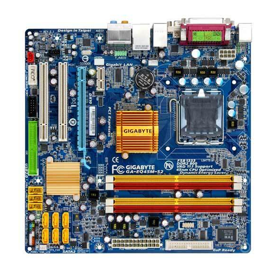
Page 7: Ga-Eq45M-S2 Motherboard Layout
GA-EQ45M-S2 Motherboard Layout PHASE LED ACPI_LED KB_MS (S0/1/3/4/5_LED) ATX_12V_2X LGA775 TPM IC COMB CPU_FAN R_USB Intel ® AUDIO F_AUDIO PCIEX1 Intel 82567LM PCIEX16 SATA2_0 SATA2_1 PCI1 SPDIF_O Intel ® ICH10DO SATA2_2 SATA2_3 CD_IN PCI2 JMicron 368 SATA2_4 SATA2_5 CODEC SPDIF_I... -
Page 8: Block Diagram
Block Diagram 1 PCI Express x16 (Note) LGA775 CPU CLK+/- DVI-D (Note) Processor (333/266/200 MHz) Level Shifter Host Interface D-Sub 12 Lanes DDR2 800/667 MHz Switch Dual Channel Memory 4 Lanes Intel ® PCI Express Bus GMCH CLK (333/266/200 MHz) 1 PCI Express x1 RJ45 BIOS... -
Page 9: Chapter 1 Hardware Installation
Chapter 1 Hardware Installation Installation Precautions The motherboard contains numerous delicate electronic circuits and components which can become damaged as a result of electrostatic discharge (ESD). Prior to installation, carefully read the user's manual and follow these procedures: Prior to installation, do not remove or break motherboard S/N (Serial Number) sticker or •... -
Page 10: Product Specifications
Celeron processor ® ® ® ® in the LGA 775 package (Go to GIGABYTE's website for the latest CPU support list.) L2 cache varies with CPU Front Side Bus 1333/1066/800 MHz FSB Chipset North Bridge: Intel Q45 Chipset ... - Page 11 Internal Connectors 1 x 24-pin ATX main power connector 1 x 8-pin ATX 12V power connector 1 x floppy disk drive connector 1 x IDE connector 6 x SATA 3Gb/s connectors 1 x CPU fan header ...
- Page 12 (Note 4) Simultaneous output for PCI Express x16 and DVI-D is not supported. (Note 5) Whether this feature is supported depends on the product being received. (Note 6) Whether the CPU/System fan speed control function is supported will depend on the CPU/ System cooler you install. GA-EQ45M-S2 Motherboard - 12 -...
-
Page 13: Installing The Cpu And Cpu Cooler
Read the following guidelines before you begin to install the CPU: • Make sure that the motherboard supports the CPU. (Go to GIGABYTE's website for the latest CPU support list.) • Always turn off the computer and unplug the power cord from the power outlet before installing the CPU to prevent hardware damage. - Page 14 CPU notches with the socket alignment keys) and gently insert the CPU into position. Step 5: Once the CPU is properly inserted, replace the load plate and push the CPU socket lever back into its locked position. GA-EQ45M-S2 Motherboard - 14 -...
-
Page 15: Installing The Cpu Cooler
1-3-2 Installing the CPU Cooler Follow the steps below to correctly install the CPU cooler on the motherboard. (The following procedure uses Intel boxed cooler as the example cooler.) ® Male Push Pin Direction of the Arrow Sign on the Male The Top Push Pin of Female... -
Page 16: Installing The Memory
• Make sure that the motherboard supports the memory. It is recommended that memory of the same capacity, brand, speed, and chips be used. (Go to GIGABYTE's website for the latest memory support list.) • Always turn off the computer and unplug the power cord from the power outlet before installing the memory to prevent hardware damage. -
Page 17: Installing A Memory
1-4-2 Installing a Memory Before installing a memory module , make sure to turn off the computer and unplug the power cord from the power outlet to prevent damage to the memory module. DDR2 DIMMs are not compatible to DDR DIMMs. Be sure to install DDR2 DIMMs on this motherboard. -
Page 18: Installing An Expansion Card
Make sure the card is securely seated in the slot and does not rock. • Removing the Card: Gently push back on the lever on the slot and then lift the card straight out from the slot. GA-EQ45M-S2 Motherboard - 18 -... -
Page 19: Back Panel Connectors
Back Panel Connectors PS/2 Keyboard and PS/2 Mouse Port Use the upper port (green) to connect a PS/2 mouse and the lower port (purple) to connect a PS/2 keyboard. Parallel Port Use the parallel port to connect devices such as a printer, scanner and etc. The parallel port is also called a printer port. - Page 20 Only microphones still MUST be con- nected to the default Mic in jack ( ). Refer to the instructions on setting up a 2/4/5.1/ 7.1-channel audio configuration in Chapter 5, "Configuring 2/4/5.1/7.1-Channel Audio." GA-EQ45M-S2 Motherboard - 20 -...
-
Page 21: Internal Connectors
Internal Connectors ATX_12V_2X SPDIF_I SPDIF_O CPU_FAN F_USB1/F_USB2/F_USB3 SYS_FAN COMA COMB DEBUG PORT* SATA2_0/1/2/3/4/5 PWR_LED CLR_CMOS F_PANEL PHASE LED F_AUDIO S0/S1/S3/S4/S5_LED CD_IN Read the following guidelines before connecting external devices: • First make sure your devices are compliant with the connectors you wish to connect. •... - Page 22 Pin No. Definition 3.3V 3.3V 3.3V -12V PS_ON(soft On/Off) Power Good 5V SB(stand by +5V) +12V +5V (Only for 2x12-pin ATX) +12V (Only for 2x12-pin ATX) 3.3V (Only for 2x12-pin ATX) GND (Only for 2x12-pin ATX) GA-EQ45M-S2 Motherboard - 22 -...
- Page 23 3/4) CPU_FAN/SYS_FAN (Fan Headers) The motherboard has a 4-pin CPU fan header and a 4-pin system fan header (CPU_FAN/ SYS_FAN). Most fan headers possess a foolproof insertion design. When connecting a fan cable, be sure to connect it in the correct orientation (the black connector wire is the ground wire). The motherboard supports CPU fan speed control, which requires the use of a CPU fan with fan speed control design.
- Page 24 • A RAID 5 configuration requires at least three hard drives. (The total number of hard drives does not have to be an even number.) • A RAID 10 configuration requires at least four hard drives and the total number of hard drives must be an even number. GA-EQ45M-S2 Motherboard - 24 -...
-
Page 25: Battery
8) PWR_LED (System Power LED Header) This header can be used to connect a system power LED on the chassis to indicate system power status. The LED is on when the system is operating. The LED keeps blinking when the system is in S1 sleep state. -
Page 26: F_Panel
LED, hard drive activity LED, speaker and etc. When connecting your chassis front panel module to this header, make sure the wire assign- ments and the pin assignments are matched correctly. GA-EQ45M-S2 Motherboard - 26 -... -
Page 27: Cd In Connector
11) F_AUDIO (Front Panel Audio Header) The front panel audio header supports Intel High Definition audio (HD) and AC'97 audio. You may connect your chassis front panel audio module to this header. Make sure the wire assignments of the module connector match the pin assignments of the motherboard header. Incorrect connection between the module connector and the motherboard header will make the device unable to work or even damage it. - Page 28 HDMI display to the graphics card and have digital audio output from the HDMI display at the same time. For information about connecting the S/PDIF digital audio cable, carefully read the manual for your expansion card. Pin No. Definition SPDIFO GA-EQ45M-S2 Motherboard - 28 -...
- Page 29 15) F_USB1/F_USB2/F_USB3 (USB Headers, Yellow) The headers conform to USB 2.0/1.1 specification. Each USB header can provide two USB ports via an optional USB bracket. For purchasing the optional USB bracket, please contact the local dealer. Pin No. Definition Power (5V) Power (5V) USB DX- USB DY-...
- Page 30 This motherboard provides a chassis detection feature that detects if the chassis cover has been removed. This function requires a chassis with chassis intrusion detection design. Pin No. Definition Signal * Whether this feature is supported depends on the product being received. GA-EQ45M-S2 Motherboard - 30 -...
-
Page 31: Clearing Cmos Jumper
20) CLR_CMOS (Clearing CMOS Jumper) Use this jumper to clear the CMOS values (e.g. date information and BIOS configurations) and reset the CMOS values to factory defaults. To clear the CMOS values, place a jumper cap on the two pins to temporarily short the two pins or use a metal object like a screwdriver to touch the two pins for a few seconds. - Page 32 POS (Power on Suspend), only the CPU stops working STR (Suspend to RAM), only the memory is working STD (Suspend to Disk), the system main power is turned off but the system can still be waked up System is turned off GA-EQ45M-S2 Motherboard - 32 -...
-
Page 33: Chapter 2 Bios Setup
To see more advanced BIOS Setup menu options, you can press <Ctrl> + <F1> in the main menu of the BIOS Setup program. To upgrade the BIOS, use either the GIGABYTE Q-Flash or @BIOS utility. Q-Flash allows the user to quickly and easily upgrade or back up BIOS without entering the •... -
Page 34: Startup Screen
Copyright(C) 2003-08 Intel Corporation. All Rights Reversed. Intel(R) ME Firmware version 5.0.2.1121 Press <CTRL - P> to enter Intel(R) ME Setup (Note) Before enabling Intel Management Engine, make sure DDR2_1 socket in Channel 0 is populated. GA-EQ45M-S2 Motherboard - 34 -... -
Page 35: The Main Menu
The Main Menu Once you enter the BIOS Setup program, the Main Menu (as shown below) appears on the screen. Use arrow keys to move among the items and press <Enter> to accept or enter a sub-menu. (Sample BIOS Version: EE) CMOS Setup Utility-Copyright (C) 1984-2009 Award Software ... - Page 36 Abandon all changes and the previous settings remain in effect. Pressing <Y> to the confirmation message will exit BIOS Setup. (Pressing <Esc> can also carry out this task.) Security Chip Configuration Use this menu to configure the TPM module function. GA-EQ45M-S2 Motherboard - 36 -...
-
Page 37: Mb Intelligent Tweaker(M.i.t.)
MB Intelligent Tweaker(M.I.T.) CMOS Setup Utility-Copyright (C) 1984-2009 Award Software MB Intelligent Tweaker(M.I.T.) Robust Graphics Booster [Auto] Item Help (Note) CPU Clock Ratio [10 X] Menu Level (Note) Fine CPU Clock Ratio [+0.5] CPU Frequency 2.66GHz( 266x10) ******** Clock Chip Control ******** Spread Spectrum [Enabled] ******** Standard Timing Control... - Page 38 Auto : Move Enter: Select +/-/PU/PD: Value F10: Save ESC: Exit F1: General Help F5: Previous Values F6: Fail-Safe Defaults F7: Optimized Defaults tRRD Options are: Auto (default), 1~15. tWTR Options are: Auto (default), 1~31. GA-EQ45M-S2 Motherboard - 38 -...
- Page 39 Options are: Auto (default), 1~31. tRFC Options are: Auto (default), 1~255. tRTP Options are: Auto (default), 1~15. Command Rate(CMD) Options are: Auto (default), 1~3. - 39 - BIOS Setup...
-
Page 40: Standard Cmos Features
IDE Channel 0, 1 Master/Slave IDE HDD Auto-Detection Press <Enter> to autodetect the parameters of the IDE/SATA device on this channel. IDE Channel 0, 1 Master/Slave Configure your IDE/SATA devices by using one of the three methods below: GA-EQ45M-S2 Motherboard - 40 -... - Page 41 • Auto Lets BIOS automatically detect IDE/SATA devices during the POST. (Default) • None If no IDE/SATA devices are used, set this item to None so the system will skip the detection of the device during the POST for faster system startup. •...
-
Page 42: Advanced Bios Features
(Default: Enabled) (Note) This item is present only if you install a CPU that supports this feature. For more information about Intel CPUs' unique features, please visit Intel's website. GA-EQ45M-S2 Motherboard - 42 -... -
Page 43: Console Redirection
CPU Multi-Threading (Note) Allows you to determine whether to enable all CPU cores and multi-threading function when using an Intel CPU that supports multi-core technology. This feature only works for operating systems ® that support multi-processor mode. Enabled Enables all CPU cores and multi-threading capability. (Default) Disabled Enables only one CPU core. - Page 44 Allows you to set a delay time for the BIOS to initialize the hard drive as the system boots up. The adjustable range is from 0 to 15 seconds. (Default: 0) ASF support This feature allows another computer to control power-on/off or carry out remote control of your computer. (Default: Enabled) GA-EQ45M-S2 Motherboard - 44 -...
-
Page 45: Advanced Chipset Features
Advanced Chipset Features CMOS Setup Utility-Copyright (C) 1984-2009 Award Software Advanced Chipset Features Init Display First [PCI] Item Help Menu Level ** VGA Setting ** Onboard VGA [Enable If No Ext PEG] x On-Chip Frame Buffer Size 32MB+2MB for GTT PAVP Mode [PAVP Lite Mode] PAVP Lite Mode... - Page 46 The table below shows the supported features of the PAVP Lite and Paranoid modes. Feature PAVP Lite PAVP Paranoid Compressed video buffer is encrypted Hardware 128-bit AES decryption Protected memory (96 MB reserved during boot) GA-EQ45M-S2 Motherboard - 46 -...
-
Page 47: Integrated Peripherals
Integrated Peripherals CMOS Setup Utility-Copyright (C) 1984-2009 Award Software Integrated Peripherals SATA RAID/AHCI Mode [Disabled] Item Help SATA Port0-3 Native Mode [Disabled] Menu Level USB Controller [Enabled] USB 2.0 Controller [Enabled] USB Keyboard Support [Disabled] USB Mouse Support [Disabled] Legacy USB storage detect [Enabled] Azalia Codec [Auto]... - Page 48 Options are: 378/IRQ7 (default), 278/IRQ5, 3BC/IRQ7, Disabled. Parallel Port Mode Selects an operating mode for the onboard parallel (LPT) port. Options are: SPP (Standard Parallel Port)(default), EPP (Enhanced Parallel Port), ECP (Extended Capabilities Port), ECP+EPP. GA-EQ45M-S2 Motherboard - 48 -...
-
Page 49: Power Management Setup
Power Management Setup CMOS Setup Utility-Copyright (C) 1984-2009 Award Software Power Management Setup ACPI Suspend Type [S3(STR)] Item Help ACPI LED Control [Enabled] Menu Level Soft-Off by PWR-BTTN [Instant-Off] PME Event Wake Up [Enabled] Power On by Ring [Enabled] Resume by Alarm [Disabled] x Date (of Month) Alarm Everyday... - Page 50 The system is turned on upon the return of the AC power. Memory The system returns to its last known awake state upon the return of the AC power. (Note) Supported on Windows Vista operating system only. GA-EQ45M-S2 Motherboard - 50 -...
-
Page 51: Pnp/Pci Configurations
PnP/PCI Configurations CMOS Setup Utility-Copyright (C) 1984-2009 Award Software PnP/PCI Configurations PCI1 IRQ Assignment [Auto] Item Help PCI2 IRQ Assignment [Auto] Menu Level : Move Enter: Select +/-/PU/PD: Value F10: Save ESC: Exit F1: General Help F5: Previous Values F6: Fail-Safe Defaults F7: Optimized Defaults PCI1 IRQ Assignment Auto... -
Page 52: Pc Health Status
F, 80 C/176 C/194 CPU/SYSTEM FAN Fail Warning Allows the system to emit warning sound if the CPU/system fan is not connected or fails. Check the fan condition or fan connection when this occurs. (Default: Disabled) GA-EQ45M-S2 Motherboard - 52 -... - Page 53 Smart FAN Control Method (Note) Specifies how to control CPU fan speed. Auto Lets BIOS control CPU fan speed. (Default) Intel(R) QST Allows CPU fan speed to be controlled by the Intel Quiet System Technology (QST). This feature requires the installation of Intel Host Embedded Control Interface (HECI) driver from the motherboard driver disk.
-
Page 54: Load Fail-Safe Defaults
Press <Enter> on this item and then press the <Y> key to load the optimal BIOS default settings. The BIOS defaults settings helps the system to operate in optimum state. Always load the Optimized defaults after updating the BIOS or after clearing the CMOS values. GA-EQ45M-S2 Motherboard - 54 -... -
Page 55: Set Supervisor/User Password
2-13 Set Supervisor/User Password CMOS Setup Utility-Copyright (C) 1984-2009 Award Software MB Intelligent Tweaker(M.I.T.) Load Fail-Safe Defaults Standard CMOS Features Load Optimized Defaults Advanced BIOS Features Set Supervisor Password Advanced Chipset Features Set User Password Integrated Peripherals Save &... -
Page 56: Save & Exit Setup
Press <Enter> on this item and press the <Y> key. This exits the BIOS Setup without saving the changes made in BIOS Setup to the CMOS. Press <N> or <Esc> to return to the BIOS Setup Main Menu. GA-EQ45M-S2 Motherboard - 56 -... -
Page 57: Security Chip Configuration
2-16 Security Chip Configuration CMOS Setup Utility-Copyright (C) 1984-2009 Award Software Security Chip Configuration LT/TXT Initialization [Disabled] Item Help Reset TPM Flag [Disabled] Menu Level Security Chip [Disabled] Security Chip state Disabled/Deactivated : Move Enter: Select +/-/PU/PD: Value F10: Save ESC: Exit F1: General Help F5: Previous Values... - Page 58 GA-EQ45M-S2 Motherboard - 58 -...
-
Page 59: Chapter 3 Drivers Installation
Chapter 3 Drivers Installation • Before installing the drivers, first install the operating system. • After installing the operating system, insert the motherboard driver disk into your optical drive. The driver Autorun screen is automatically displayed which looks like that shown in the screen shot below. -
Page 60: Application Software
Application Software This page displays all the utilities and applications that GIGABYTE develops and some free software. You can click the Install button on the right of an item to install it. Technical Manuals This page provides GIGABYTE's application guides, content descriptions for this driver disk, and the motherboard manuals. -
Page 61: Contact
Contact For the detailed contact information of the GIGABYTE Taiwan headquarter or worldwide branch offices, click the URL on this page to link to the GIGABYTE website. System This page provides the basic system information. - 61 - Drivers Installation... -
Page 62: Download Center
Download Center To update the BIOS, drivers, or applications, click the Download Center button to link to the GIGABYTE Web site. The latest version of the BIOS, drivers, or applications will be displayed. GA-EQ45M-S2 Motherboard - 62 -... -
Page 63: Chapter 4 Unique Features
Chapter 4 Unique Features Xpress Recovery2 Xpress Recovery2 is a utility that allows you to quickly compress and back up your system data and perform restoration of it. Supporting NTFS, FAT32, and FAT16 file systems, Xpress Recovery2 can back up data on PATA and SATA hard drives and restore it. Before You Begin: •... - Page 64 Xpress Recovery2 will automatically create a new partition to store the backup image file. Step 1: Step 2: Select BACKUP to start backing up your hard When finished, go to Disk Management to drive data. check disk allocation. GA-EQ45M-S2 Motherboard - 64 -...
- Page 65 D. Using the Restore Function in Xpress Recovery2 Select RESTORE to restore the backup to your hard drive in case the system breaks down. The RESTORE option will not be present if no backup is created before. E. Removing the Backup Step 1: Step 2: If you wish to remove the backup file, select...
-
Page 66: Bios Update Utilities
4-2-1 Updating the BIOS with the Q-Flash Utility A. Before You Begin: 1. From GIGABYTE's website, download the latest compressed BIOS update file that matches your motherboard model. 2. Extract the file and save the new BIOS file (e.g. EQ45MS2.F1) to your floppy disk, USB flash drive, or hard drive. - Page 67 B. Updating the BIOS When updating the BIOS, choose the location where the BIOS file is saved. The follow procedure assumes that you save the BIOS file to a floppy disk. Step 1: 1. Insert the floppy disk containing the BIOS file into the floppy disk drive. In the main menu of Q-Flash, use the up or down arrow key to select Update BIOS from Drive and press <Enter>.
- Page 68 Load Optimized Defaults Press <Y> to load BIOS defaults Step 6: Select Save & Exit Setup and then press <Y> to save settings to CMOS and exit BIOS Setup. The procedure is complete after the system restarts. GA-EQ45M-S2 Motherboard - 68 -...
-
Page 69: Updating The Bios With The @Bios Utility
BIOS or a system that is unable to start. 3. Do not use the G.O.M. (GIGABYTE Online Management) function when using @BIOS. 4. GIGABYTE product warranty does not cover any BIOS damage or system failure resulting from an inadequate BIOS flashing. -
Page 70: Dynamic Energy Saver Advanced
The Dynamic Energy Saver Advanced Interface A. Meter Mode In Meter Mode, GIGABYTE Dynamic Energy Saver Advanced shows how much power they have saved in a set period of time. Meter Mode - Button Information Table... - Page 71 B. Total Mode In Total Mode, users are able to see how much total power savings they have accumulated in a set period of time since activating Dynamic Energy Saver Advanced for the first time (Note 4) Total Mode - Button Information Table Button Description Dynamic Energy Saver On/Off Switch (Default: Off) Motherboard Phase LED On/Off Switch (Default: On)
-
Page 72: Ultra Tpm
• Though the TPM delivers the latest data security technology, it does not guarantee data integrity or give hardware protection. GIGABYTE is not liable for loss of encrypted data as a result of hardware damage. A. Before installing Ultra TPM, follow the steps below in sequence: Step 1: Turn on your computer and enter the BIOS Setup program. -
Page 73: Q-Share
Q-Share, you are able to share your data with computers on the same network, making full use of Internet resources. Directions for using Q-Share After installing Q-Share from the motherboard driver disk, go to Start>All Programs>GIGABYTE> Q-Share.exe to launch the Q-Share tool. Find the Q-Share icon in your system tray and right-click on this icon to configure the data sharing settings. -
Page 74: Time Repair
• Each storage volume can accommodate 64 shadow copies. When this limit is reached, the oldest shadow copy will be deleted and unable to be restored. Shadow copies are read-only so you cannot edit the contents of a shadow copy. GA-EQ45M-S2 Motherboard - 74 -... -
Page 75: Chapter 5 Appendix
Chapter 5 Appendix Configuring SATA Hard Drive(s) To configure SATA hard drive(s), follow the steps below: A. Install SATA hard drive(s) in your computer. B. Configure SATA controller mode in BIOS Setup. C . Configure a RAID array in RAID BIOS. (Note 1) D. - Page 76 The BIOS Setup menus described in this section may differ from the exact settings for your motherboard. The actual BIOS Setup menu options you will see shall depend on the motherboard you have and the BIOS version. GA-EQ45M-S2 Motherboard - 76 -...
-
Page 77: Create Raid Volume
C. Configuring a RAID array in RAID BIOS Enter the RAID BIOS setup utility to configure a RAID array. Skip this step and proceed to the installation of Windows operating system for a non-RAID configuration. Step 1: After the POST memory test begins and before the operating system boot begins, look for a message which says "Press <Ctrl-I>... - Page 78 Select Disks Strip Size : 128KB Capacity : 223.6 GB Create Volume [ HELP ] The following are typical values: RAID0 - 128KB RAID10 - 64KB RAID5 - 64KB []-Change [TAB]-Next [ESC]-Previous Menu [ENTER]-Select Figure 5 GA-EQ45M-S2 Motherboard - 78 -...
- Page 79 Step 5: Enter the array capacity and press <Enter>. Finally press <Enter> on the Create Volume item to begin creating the RAID array. When prompted to confirm whether to create this volume, press <Y> to confirm or <N> to cancel (Figure 6). Intel(R) Matrix Storage Manager option ROM v8.5.0.1030 ICH10R/DO wRAID5 Copyright(C) 2003-08 Intel Corporation.
-
Page 80: Delete Raid Volume
[ HELP ] Are you sure you want to delete "Volume0"? (Y/N) : Deleting a volume will reset the disks to non-RAID. WARNING: ALL DISK DATA WILL BE DELETED. []-Select [ESC]-Previous Menu [DEL]-Delete Volume Figure 8 GA-EQ45M-S2 Motherboard - 80 -... -
Page 81: Making A Sata Raid/Ahci Driver Diskette
5-1-2 Making a SATA RAID/AHCI Driver Diskette (Required for AHCI and RAID Mode) To successfully install operating system onto SATA hard drive(s) that is/are configured to RAID/AHCI mode, you need to install the SATA controller driver during the OS installation. Without the driver, the hard drive may not be recognized during the Windows setup process. -
Page 82: Installing The Sata Raid/Ahci Driver And Operating System
Select the SCSI Adapter you want from the following list, or press ESC to return to the previous screen. Intel(R) ICH7R/DH SATA RAID Controller Intel(R) ICH7MDH SATA RAID Controller Intel(R) ICH8R/ICH9R/ICH10R/DO SATA RAID Controller Intel(R) ICH8M-E/ICH9M-E SATA RAID Controller ENTER=Select F3=Exit Figure 2 GA-EQ45M-S2 Motherboard - 82 -... - Page 83 B. Installing Windows Vista (The procedure below assumes that only one RAID array exists in your system.) Step 1: Restart your system to boot from the Windows Vista setup disk and perform standard OS installation steps. When a screen similar to that below appears, select Load Driver. (Figure 3). Figure 3 Step 2: Specify the location where the driver is saved, such as your floppy disk or USB flash drive (Figure 4).
- Page 84 Controller and press Next. Figure 5 Step 4: After the driver is loaded, select the RAID/AHCI drive(s) where you want to install the operating system and then press Next to continue the OS installation (Figure 6). Figure 6 GA-EQ45M-S2 Motherboard - 84 -...
-
Page 85: Rebuilding An Array
Rebuilding an Array: Rebuilding is the process of restoring data to a hard drive from other drives in the array. Rebuilding applies only to fault-tolerant arrays such as RAID 1, RAID 10, or RAID 5 arrays. The procedures below assume a new drive is added to replace a failed drive to rebuild a RAID 1 array. Intel ICH10DO SATA controller: Turn off your computer and replace the failed hard drive with a new one. - Page 86 When the message "The rebuild was completed successfully," appears, click OK to complete. Step 6: After the RAID 1 volume rebuilding, click the volume and its status in the information pane will display as Normal. GA-EQ45M-S2 Motherboard - 86 -...
-
Page 87: Configuring Audio Input And Output
Configuring Audio Input and Output 5-2-1 Configuring 2/4/5.1/7.1-Channel Audio The motherboard provides six audio jacks on the back panel which support 2/4/5.1/7.1-channel audio. The picture to the right shows the default audio jack Center/Subwoofer Line In assignments. Speaker Out The integrated HD (High Definition) audio provides Front Speaker Out Rear Speaker Out jack retasking capability that allows the user to change... - Page 88 Click Device advanced settings on the top right cor- ner on the Speaker Configuration tab to open the Device advanced settings dialog box. Select the Mute the rear output device, when a front headphone plugged in check box. Click OK to complete. GA-EQ45M-S2 Motherboard - 88 -...
-
Page 89: Configuring S/Pdif In/Out
5-2-2 Configuring S/PDIF In/Out A. S/PDIF In: The S/PDIF in cable (optional) allows you to input digital audio signals to the computer for audio processing. S/PDIF In Cable Coaxial Optical S/PDIF In S/PDIF In 1. Installing the S/PDIF In Cable: Step 1: Step 2: First, attach the connector at the end of the cable... - Page 90 Connect a S/PDIF coaxial cable or a S/PDIF optical cable (either one) to an external decoder for transmitting the S/PDIF digital audio signals. 2. Configuring S/PDIF Out: On the Digital Output screen, click the Default Format tab and then select the sample rate and bit depth. Click OK to complete. GA-EQ45M-S2 Motherboard - 90 -...
-
Page 91: Configuring Microphone Recording
5-2-3 Configuring Microphone Recording Step 1: After installing the audio driver, the HD Audio Manager icon will appear in the notification area. Double- click the icon to access the HD Audio Manager. Step 2: Connect your microphone to the Mic in jack (pink) on the back panel or the Mic in jack (pink) on the front panel. - Page 92 Step 1: Locate the Volume icon in the notification area and right-click on this icon. Select Recording Devices. Step 2: On the Recording tab, right-click on an empty space and select Show Disabled Devices. GA-EQ45M-S2 Motherboard - 92 -...
-
Page 93: Using The Sound Recorder
Step 3: When the Stereo Mix item appears, right-click on this item and select Enable. Then set it as the default device. Step 4: Now you can access the HD Audio Manager to configure Stereo Mix and use Sound Recorder to record the sound. -
Page 94: Troubleshooting
1 long, 2 short: Monitor or graphics card error 1 long, 3 short: Keyboard error 1 long, 9 short: BIOS ROM error Continuous long beeps: Graphics card not inserted properly Continuous short beeps: Power error GA-EQ45M-S2 Motherboard - 94 -... -
Page 95: Troubleshooting Procedure
5-3-2 Troubleshooting Procedure If you encounter any troubles during system startup, follow the troubleshooting procedure below to solve the problem. START Turn off the power. Remove all peripherals, connecting cables, and power cord etc. Make sure the motherboard does not short-circuit with the chassis Isolate the short circuit. - Page 96 If the procedure above is unable to solve your problem, contact the place of purchase or local dealer for help. Or go to the Support\Technical Service Zone page to submit your question. Our customer service staff will reply you as soon as possible. GA-EQ45M-S2 Motherboard - 96 -...
-
Page 97: Regulatory Statements
"end of life" product. Restriction of Hazardous Substances (RoHS) Directive Statement GIGABYTE products have not intended to add and safe from hazardous substances (Cd, Pb, Hg, Cr+6, PBDE and PBB). The parts and components have been carefully selected to meet RoHS requirement. - Page 98 "end of life" products, and generally improve our quality of life by ensuring that potentially hazardous substances are not released into the environment and are disposed of properly. China Restriction of Hazardous Substances Table The following table is supplied in compliance with China's Restriction of Hazardous Substances (China RoHS) requirements: GA-EQ45M-S2 Motherboard - 98 -...
- Page 99 - 99 - Appendix...
- Page 100 GA-EQ45M-S2 Motherboard - 100 -...
- Page 101 - 101 - Appendix...
- Page 102 GA-EQ45M-S2 Motherboard - 102 -...
- Page 103 TEL: +86-24-83992901 GIGA-BYTE SINGAPORE PTE. LTD. - Singapore FAX: +86-24-83992909 WEB address : http://www.gigabyte.sg GIGABYTE TECHNOLOGY (INDIA) LIMITED - India Thailand WEB address : http://www.gigabyte.in ...
- Page 104 WEB address : http://www.giga-byte.kz Czech Republic You may go to the GIGABYTE website, select your language WEB address : http://www.gigabyte.cz in the language list on the top right corner of the website. GIGABYTE Global Service System...