Cisco 7301 Installation And Configuration Manual
Configuration guide
Hide thumbs
Also See for 7301:
- Regulatory compliance and safety information manual (70 pages) ,
- Manual (111 pages) ,
- Quick start manual (35 pages)
Table of Contents
Advertisement
Quick Links
Download this manual
See also:
Manual
Cisco 7301 Installation and Configuration
Guide
Product Number: Cisco 7301
THE SPECIFICATIONS AND INFORMATION REGARDING THE PRODUCTS IN THIS MANUAL ARE SUBJECT TO
CHANGE WITHOUT NOTICE. ALL STATEMENTS, INFORMATION, AND RECOMMENDATIONS IN THIS
MANUAL ARE BELIEVED TO BE ACCURATE BUT ARE PRESENTED WITHOUT WARRANTY OF ANY KIND,
EXPRESS OR IMPLIED. USERS MUST TAKE FULL RESPONSIBILITY FOR THEIR APPLICATION OF ANY
PRODUCTS.
Americas Headquarters
Cisco Systems, Inc.
170 West Tasman Drive
San Jose, CA 95134-1706
USA
http://www.cisco.com
Tel: 408 526-4000
800 553-NETS (6387)
Fax: 408 527-0883
Customer Order Number:
Text Part Number: OL-5418-07
Advertisement
Chapters
Table of Contents
Troubleshooting

Related Manuals for Cisco 7301


Summary of Contents for Cisco 7301
- Page 1 Cisco 7301 Installation and Configuration Guide Product Number: Cisco 7301 THE SPECIFICATIONS AND INFORMATION REGARDING THE PRODUCTS IN THIS MANUAL ARE SUBJECT TO CHANGE WITHOUT NOTICE. ALL STATEMENTS, INFORMATION, AND RECOMMENDATIONS IN THIS MANUAL ARE BELIEVED TO BE ACCURATE BUT ARE PRESENTED WITHOUT WARRANTY OF ANY KIND, EXPRESS OR IMPLIED.
- Page 2 You can determine whether your equipment is causing interference by turning it off. If the interference stops, it was probably caused by the Cisco equipment or one of its peripheral devices. If the equipment causes interference to radio or television reception, try to correct the interference by using one or more of the following measures: •...
-
Page 3: Table Of Contents
About the SFP GBIC Module Installing the SFP GBIC Module 1-11 Rack-Mounting, Tabletop Installation, and Cabling C H A P T E R Preparing to Install the Cisco 7301 Router Tools and Parts Required Electrical Equipment Guidelines Preventing Electrostatic Discharge Damage Site Requirement Guidelines... - Page 4 Performing a Basic Configuration Using the Setup Facility 3-11 Configuring Global Parameters 3-11 Configuring the Native Gigabit Ethernet Interfaces 3-14 Configuring Port Adapter Interfaces 3-16 Performing a Basic Configuration Using Global Configuration Mode 3-20 Enabling the Second Processor 3-20 Cisco 7301 Installation and Configuration Guide OL-5418-07...
- Page 5 Saving the Running Configuration to NVRAM 3-27 Checking the Running Configuration Settings 3-27 Performing Other Configuration Tasks 3-27 Upgrading ROMmon on the Cisco 7301 3-27 Using the show rom-monitor Command and showmon Commands 3-28 Using the upgrade rom-monitor Command 3-28...
- Page 6 Using the cd Command Using the show Command Using the pwd Command Using the dir Command Using the format Command Using the mkdir Command B-10 Using the rmdir Command B-11 Using the delete Command B-11 Cisco 7301 Installation and Configuration Guide OL-5418-07...
- Page 7 Bit 11 and Bit 12 Bit 13 Bit 15 Displaying the Configuration Register While Running Cisco IOS Displaying the Configuration Register While Running ROM Monitor Setting the Configuration Register While Running Cisco IOS Setting the Configuration Register While Running ROM Monitor...
- Page 8 Contents Cisco 7301 Installation and Configuration Guide OL-5418-07...
-
Page 9: Document Version History
This publication describes the installation and configuration of the Cisco 7301 router, replacement or upgrading of field replaceable units (FRUs), and troubleshooting of the Cisco 7301 hardware. The purpose of this guide is to enable the safe and efficient installation of the Cisco 7301 router. Cisco 7301 Installation and Configuration Guide... -
Page 10: Audience
This publication is primarily designed for the person responsible for installing, maintaining, and troubleshooting the Cisco 7301 router. The users of this guide should be familiar with electronic circuitry and wiring practices and have experience as electronic or electromechanical technicians. Users of this guide should also have experience in installing high-end networking equipment. -
Page 11: Warning Definition
éviter les accidents. Pour prendre connaissance des traductions des avertissements figurant dans les consignes de sécurité traduites qui accompagnent cet appareil, référez-vous au numéro de l'instruction situé à la fin de chaque avertissement. CONSERVEZ CES INFORMATIONS Cisco 7301 Installation and Configuration Guide OL-5418-07... - Page 12 Al final de cada advertencia encontrará el número que le ayudará a encontrar el texto traducido en el apartado de traducciones que acompaña a este dispositivo. GUARDE ESTAS INSTRUCCIONES Cisco 7301 Installation and Configuration Guide OL-5418-07...
- Page 13 Använd det nummer som finns i slutet av varje varning för att hitta dess översättning i de översatta säkerhetsvarningar som medföljer denna anordning. SPARA DESSA ANVISNINGAR Cisco 7301 Installation and Configuration Guide OL-5418-07...
- Page 14 Brug erklæringsnummeret efter hver advarsel for at finde oversættelsen i de oversatte advarsler, der fulgte med denne enhed. GEM DISSE ANVISNINGER Cisco 7301 Installation and Configuration Guide viii OL-5418-07...
- Page 15 Preface Document Organization Cisco 7301 Installation and Configuration Guide OL-5418-07...
-
Page 16: Related Documentation
To see translations of the warnings that appear in this publication, refer to the Regulatory Compliance and Safety Information document that accompanied the equipment. Related Documentation Your Cisco 7301 router and the Cisco IOS software running on it contain extensive features and functionality, which are documented in the following resources: •... -
Page 17: Obtaining Documentation And Submitting A Service Request
IOS requirements for individual hardware modules or components. To access Software Advisor, click Log In at Cisco.com and go to Support, Tools and Resources. Access to this tool is limited to users with Cisco.com login accounts. - Page 18 Preface Obtaining Documentation and Submitting a Service Request Cisco 7301 Installation and Configuration Guide OL-5418-07...
-
Page 19: Cisco 7301 Overview
To see translations of the warnings that appear in this publication, refer to the CRegulatory Compliance and Safety Information for the Cisco 7301 Router publication that accompanied this device. Statement 1071... -
Page 20: Chapter 1 Cisco 7301 Overview
Cisco 7301 Overview Cisco 7301 Features Cisco 7301 Features Each Cisco 7301 router consists of the following features: Small form-factor—One rack-unit (RU) high with stacking capability: • 1.73 in. x 17.3 in. x 13.87 in. (4.39 cm x 43.9 cm x 35.23 cm). The weight is approximately 10.5 lbs (4.76 kg). -
Page 21: Cisco 7301 Hardware Overview
Temperature sensor 1 (U62) is on the underneath side of the board. Cisco 7301 Hardware Overview This section provides you with an overview of the hardware including LEDs, front and rear views, and interior part identification. Cisco 7301 Installation and Configuration Guide OL-5418-07... -
Page 22: Cisco 7301 Hardware Overview
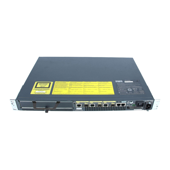
Gigabit Ethernet 0/0—SFP GBIC port 13 Alarm port Gigabit Ethernet 0/1—RJ-45 port 14 Power switch Gigabit Ethernet 0/1—SFP GBIC port 15 CompactFlash Disk slot Gigabit Ethernet 0/2—RJ-45 port Gigabit Ethernet 0/2—SFP GBIC port 16 Power connector Cisco 7301 Installation and Configuration Guide OL-5418-07... -
Page 23: Leds
LED is on constantly on STATUS System status Amber while the — — system boots Green when the In the Power Up state, No, remains system is the LED is on constantly on operational Cisco 7301 Installation and Configuration Guide OL-5418-07... -
Page 24: Rear View
BCM 1250 integrated dual processor that operates at an internal clock speed of 700 MHz. The • BCM 1250 processor maintains and executes the system management functions for the Cisco 7301 router. The processor also performs some memory and environmental monitoring functions. -
Page 25: System Management Functions
Checking the Shipping Container Contents Use the Cisco 7301 components list to check the contents of the Cisco 7301 router shipping container. Do not discard the shipping container. You need the container if you move or ship the Cisco 7301 router in the future. -
Page 26: Cisco 7301 Router Installation Checklist
Cisco 7301 Components List Component Description Received Chassis Cisco 7301 chassis configured with a single or dual AC or DC power supply and port adapter filler plate. Accessories: The following accessories might arrive in separate shipping containers: Rack-mount and Two rack-mount brackets, one cable-management bracket, four 12-24 x 0.5-in. -
Page 27: About The Sfp Gbic Module
You may have ordered a SFP (small form-factor pluggable) Gigabit Interface Converter (GBIC) module with your Cisco 7301 router. You must install the SFP GBIC module. It is shipped separately to prevent damage during shipment. After reading this section, use the installation instructions in the “Installing... - Page 28 Invisible laser radiation may be emitted from disconnected fibers or connectors. Do not stare into beams or view directly with optical instruments. Statement 1051 Class 1 laser product. Statement 1008 Warning Class 1 LED product. Statement 1027 Warning Cisco 7301 Installation and Configuration Guide 1-10 OL-5418-07...
-
Page 29: Installing The Sfp Gbic Module
Statement 94 Installing the SFP GBIC Module Figure 1-6 Inserting a SFP GBIC Module into the Cisco 7301 Gigabit Ethernet Port 0/1 G B IC ET HE RN ET... -
Page 30: Installing The Sfp Gbic Module
Installing the SFP GBIC Module For information on removing and installing other options, see Chapter 4, “Installing and Removing Field-Replaceable Units.” For rack-mounting and cabling procedures, see Chapter 2, “Rack-Mounting, Tabletop Installation, and Cabling.” Cisco 7301 Installation and Configuration Guide 1-12 OL-5418-07... - Page 31 Rack-Mounting, Tabletop Installation, and Cabling This chapter explains how to install a Cisco 7301 router in a rack in a general tabletop or workbench installation, how to attach cables, and how to power on the router. This chapter contains the following sections: •...
-
Page 32: Rack-Mounting, Tabletop Installation, And Cabling
Chassis fully configured with a port adapter ~ 10.5 lb (4.76 kg) Tools and Parts Required Your Cisco 7301 chassis is fully assembled at the factory; no assembly is required. However, you need the following tools and equipment to install the chassis and the rack-mount and cable-management kit: Number 2 Phillips screwdriver •... -
Page 33: C H A P T E R 2 Rack-Mounting, Tabletop Installation, And Cabling
Chapter 2 Rack-Mounting, Tabletop Installation, and Cabling Preparing to Install the Cisco 7301 Router – One grounding wire—6-AWG, 0.162-inch (4.115-mm) diameter, with approximately 0.108-inch (2.743-mm) insulation, for a total wire diameter of approximately 0.27 inches (6.858 mm). The wire length depends on your router location and site environment. -
Page 34: Site Requirement Guidelines
F (0•C through 40•C), and keep the area around the chassis as free from dust as is practical. Planning a proper location for the Cisco 7301 router and the layout of your equipment rack or wiring closet is essential for successful system operation. Equipment placed too close together or inadequately ventilated can cause system overtemperature conditions. -
Page 35: General Tabletop Or Workbench Installation
“Site Requirement Guidelines” section on page 2-4. When installing a Cisco 7301 router on a workbench or tabletop, ensure that the surface is clean and in a safe location and that you have considered the following: The router requires at least 3 inches (7.62 cm) of clearance at the inlet and exhaust vents (the front •... -
Page 36: Rack-Mounting A Cisco 7301 Router
This section explains how to install the rack-mount and cable-management brackets at the front and the rear of a Cisco 7301 router. Before installing the chassis in the rack, you must install a rack-mount bracket on each side of the front or rear of the chassis. -
Page 37: Installing Rack-Mount Brackets On The Front Of The Chassis
Depending on the bracket holes you use, the router will protrude or be recessed in the rack. To install the rack-mount and cable-management brackets on a Cisco 7301 router for a front rack-mount configuration, complete the following steps: Locate the threaded holes in the front sides of the chassis. -
Page 38: Attaching The Cable-Management Bracket
Cable-management bracket M4 x 20-mm screw Step 1 Align the cable-management bracket to the rack-mount bracket on the left side of the Cisco 7301 router. Step 2 Using a Phillips screwdriver and the screw, thread and tighten the screw to the M4 x 20-mm cable-management bracket. -
Page 39: Installing The Chassis In The Rack
Rack-Mounting, Tabletop Installation, and Cabling Installing the Router To install the rack-mount and cable-management brackets on a Cisco 7301 router for a rear rack-mount configuration, complete the following steps: Locate the threaded holes in the rear sides of the chassis. -
Page 40: Two-Post Rack Installation
Note (43.9 cm). The height of the chassis is 1.73 inches (4.39 cm). Airflow through the chassis is from front to back. Figure 2-6 Installing the Cisco 7301 Router in a Two-Post Rack SLOT 1 GIGAB IT ETHE RNET 0/0... -
Page 41: Four-Post Rack Installation
(43.9 cm). The height of the chassis is 1.73 inches (4.39 cm). Airflow through the chassis is from front to back. Figure 2-7 Installing the Cisco 7301 Router in a Four-Post Rack GIGA BIT ETH SLO T 1 ERN ET 0/0... -
Page 42: Attaching A Chassis Ground Connection
Two Phillips machine screws with locking washers—M5 (metric), 0.031-inch (0.8-mm) pitch, • 0.315-inch (8-mm) length. These screws are not available from Cisco Systems; they are available from a commercial hardware vendor. One grounding wire—6-AWG, 0.162-inch (4.115-mm) diameter, with approximately 0.108-inch •... - Page 43 Chassis ground connector Screws Grounding lug Wire The grounding lug and Phillips scres are not available from Cisco Systems. Get the grounding lug from Note an electrical-connector vendor and the screws from a hardware vendor. See “Tools and Parts Required”...
-
Page 44: Connecting Port Adapter Cables
Connecting Port Adapter Cables Connecting Port Adapter Cables The instructions for connecting the cables for the port adapter installed in the Cisco 7301 router are contained in the respective configuration notes for each port adapter. For example, if you are connecting... - Page 45 If your cable was purchased from Cisco, pin 1 will be white on one connector, and pin 8 will be white on the other (a roll-over cable reverses pins 1 and 8, 2 and 7, 3 and 6, and 4 and 5).
-
Page 46: Connecting Native Gigabit Ethernet Cables
3-14, for information on configuring and troubleshooting the Gigabit Ethernet interfaces. The Cisco 7301 router has three native Gigabit Ethernet interfaces and six physical Gigabit Ethernet ports, three RJ-45 ports (copper) and three SFP GBIC ports (optical). Only three of the six ports can be in use at any one time. -
Page 47: Attaching The Sfp Gbic Interface Cables
Rack-Mounting, Tabletop Installation, and Cabling Connecting I/O Cables The RJ-45 port supports standard straight-through and crossover Category 5 unshielded twisted-pair (UTP) cables with RJ-45 connectors. Cisco Systems does not supply Category 5 UTP cables; these cables are available commercially. Appendix A, “Specifications,”... - Page 48 Optical fiber cables are commercially available; they are not available from Cisco Systems. Attaching Multimode and Single-Mode Optical Fiber Cables If you ordered a Gigabit Ethernet SFP GBIC module with your Cisco 7301 router, it is one of three types listed in...
-
Page 49: Attaching The Mode-Conditioning Patch Cord
The effect of DMD can be overcome by conditioning the launch characteristics of a laser source. A practical means of performing this conditioning is to use a device called a mode-conditioning patch cord. Cisco 7301 Installation and Configuration Guide 2-19 OL-5418-07... - Page 50 Ensure that you connect the TX and RX ports on one end of the patch cord to the RX and TX ports (respectively) on the other end. Connect TX to RX and RX to TX. This completes the procedures for connecting the I/O cables. Cisco 7301 Installation and Configuration Guide 2-20 OL-5418-07...
-
Page 51: Attaching The Alarm Port Cable
S T A T U S Alarm port If you have an alarm system, attach the alarm cable to the Cisco 7301 router alarm port. The alarm port cable is not provided by Cisco Systems. Insert the cable connector into the alarm port. The cable connector cannot be incorrectly inserted into the alarm port. -
Page 52: Connecting Power
“Connecting Power” section on page 2-22 to complete the installation. Connecting Power This section provides the procedures for connecting AC-input and DC-input power to your Cisco 7301 router. Warning This unit might have more than one power supply connection. All connections must be removed to de-energize the unit. -
Page 53: Connecting Dc-Input Power
Make certain the lead color coding you choose for the DC-input power supply matches lead color coding used at the DC power source. Warning When you install the unit, the ground connection must always be made first and disconnected last. Statement 1046 Cisco 7301 Installation and Configuration Guide 2-23 OL-5418-07... - Page 54 Dual DC power connector + and – embossed on connector Insert the –V and +V leads into the DC plug that ships with the Cisco 7301 router. The plug allows you Step 4 to unplug the DC wires from the power supply without having to unscrew the leads.
- Page 55 Switch the circuit breaker to the on position. Step 7 Press the power switch to turn on the router. Step 8 For information on Cisco 7301 product specifications and power supply, refer to Cisco 7301 Router Data Sheet at the following URL: https://www.cisco.com/en/US/prod/collateral/routers/ps352/ps4972/product_data_sheet09186a008014 611a.html After powering off the router, wait a minimum of 30 seconds before powering it on again.
- Page 56 Chapter 2 Rack-Mounting, Tabletop Installation, and Cabling Connecting Power Cisco 7301 Installation and Configuration Guide 2-26 OL-5418-07...
-
Page 57: Functional Overview
Cisco IOS software configuration documentation set that corresponds to the software release installed on your Cisco hardware. To configure a Cisco 7301 router from a console, you need to connect a terminal to the router console port. Functional Overview This section provides a functional overview of the Cisco 7301 router. -
Page 58: Chapter 3 Starting And Configuring The Router
The port adapter slot in the Cisco 7301 router is numbered slot 1. Port adapter slot 0 is always reserved for logical ports 10/100/1000. -
Page 59: Mac Address
Each address is reserved for a specific port and slot in the router regardless of whether a port adapter resides in that slot. The MAC address for the port adapter slot in the Cisco 7301 is slot 0. You can remove a port adapter and insert it into another router without causing the MAC addresses to move around the network or be assigned to multiple devices. -
Page 60: Online Insertion And Removal
The system recognizes the signals and the sequence in which it receives them. When you remove or insert a port adapter or service adapter in a Cisco 7301 router, the pins send signals to notify the system, which then performs as follows: Rapidly scans the system for configuration changes. -
Page 61: Environmental Monitoring And Reporting Functions
All DC power remains disabled until you toggle the power switch. Table 3-1 lists the typical temperature thresholds for the Cisco 7301 router, and Table 3-2 lists the DC power thresholds for the normal, warning, and critical (power supply-monitored) levels. -
Page 62: Reporting Functions
+1.37 Reporting Functions The Cisco 7301 router displays warning messages on the console if chassis interface-monitored parameters exceed a desired threshold. You can also retrieve and display environmental status reports with the show environment, show environment all, show environment last, and show environment table commands. - Page 63 These thresholds are related to those listed in Table 3-1 Table 3-2. The display also lists the shutdown threshold for the system. Following is sample output of the show environment table command for a Cisco 7301 router: Router# show environment table Sample Point LowCritical...
-
Page 64: Fan Failures
Queued messages: %ENVM-1-SHUTDOWN: Environmental Monitor initiated shutdown For complete descriptions and instructions for the environmental monitor commands, refer to the Cisco IOS Configuration Fundamentals Configuration Guide and Cisco IOS Configuration Fundamentals Command Reference publications, which are available online. Checking Conditions Prior to System Startup Check the following conditions before you start your router: The port adapter is inserted in its slot and the port adapter latch is in the locked position. -
Page 65: Starting The System And Observing Initial Conditions
Starting the System and Observing Initial Conditions After installing your Cisco 7301 router and connecting cables, start the router as follows: At the front of the router, place the power switch on the power supply in the on (|) position. -
Page 66: Configuring A Cisco 7301 Router
(SDM) User Guide for the Cisco 7200 VXR and Cisco 7301 Routers documentation for more information. You can configure your Cisco 7301 router using one of the procedures described in the following sections: Performing a Basic Configuration Using AutoInstall, page 3-10 •... -
Page 67: Performing A Basic Configuration Using The Setup Facility
Cisco IOS Configuration Fundamentals Configuration Guide and Cisco IOS Configuration Fundamentals Command Reference publications for information about how AutoInstall works. Complete the following steps to prepare your Cisco 7301 router for the AutoInstall process: Step 1 Attach the appropriate synchronous serial cable to synchronous serial interface 0 on the router. - Page 68 Would you like to enter the initial configuration dialog? [yes]: First, would you like to see the current interface summary? [yes]: In the following example, the summary shows a Cisco 7301 router at first-time startup; that is, nothing is configured.
- Page 69 To configure IP routing, enter yes (the default) or press Return, and then select an interior routing protocol: Configure IP? [yes]: Configure IGRP routing? [yes]: Your IGRP autonomous system number [1]: 15 Cisco 7301 Installation and Configuration Guide 3-13 OL-5418-07...
-
Page 70: Configuring The Native Gigabit Ethernet Interfaces
Changing the Media Type To be able to use a particular media type, use Cisco IOS to select the media type. This is done by using the media-type interface command:... - Page 71 After changing the media type, configure the speed and duplex transmission modes to appropriately Step 1 match the new interface characteristics. Changing the speed and duplex of a Cisco 7301 router Gigabit Ethernet interface is done using the speed and duplex interface commands.
-
Page 72: Configuring Port Adapter Interfaces
Consult with your network administrator for this information. Note Only one port adapter can be installed in the Cisco 7301 at one time. Following are three examples of three different interfaces that might be used. Configuring ATM Interfaces In the following example, an ATM interface in slot 1 is configured for an ATM LAN using IP. - Page 73 3-27.) If you do not save the configuration settings that you created in the router using configuration mode and the setup facility, your configuration will be lost the next time you reload the router. Cisco 7301 Installation and Configuration Guide 3-17 OL-5418-07...
- Page 74 If additional synchronous serial interfaces are available in your system, you are prompted for their Note configurations as well. Cisco 7301 Installation and Configuration Guide 3-18 OL-5418-07...
- Page 75 For information on additional interface configuration and specific system configurations, refer to the modular configuration and modular command reference publications in the Cisco IOS software configuration documentation set that corresponds to the software release installed on your Cisco hardware. Cisco 7301 Installation and Configuration Guide...
-
Page 76: Performing A Basic Configuration Using Global Configuration Mode
Enabling the Second Processor Performing a Basic Configuration Using Global Configuration Mode You can configure a Cisco 7301 router manually if you prefer not to use the setup facility or AutoInstall. Complete the following steps to configure the router manually: Connect a console terminal to the console port. - Page 77 Starting and Configuring the Router Enabling the Second Processor Only the following port adapters are supported in the punt path (Processor 0, processing Cisco IOS) on Cisco IOS Release 12.3(14)YM and later releases of Cisco IOS Release 12.3YM: PA-A3-OC3 (SMI/SML/MM) •...
-
Page 78: Error Messages
Internet address is 155.1.1.1/16 Broadcast address is 255.255.255.255 Address determined by setup command MTU is 1500 bytes Helper address is not set Directed broadcast forwarding is disabled Outgoing access list is not set Cisco 7301 Installation and Configuration Guide 3-22 OL-5418-07... -
Page 79: Using The Show Mpf Cpu Command
Use the show mpf cpu history command to graph output of the second CPU utilization for the last 60 seconds, 60 minutes, and 72 hours. Router# show mpf cpu history slns 12:12:40 AM Saturday Nov 18 2000 UTC 3333333333333333333333333333333333333333333333333333333333 3333333333333333333333333333333333333333333333333333333333 30 *************************** 20 *************************** 10 *************************** 0..5..1..1..2..2..3..3..4..4..5..5..Cisco 7301 Installation and Configuration Guide 3-23 OL-5418-07... -
Page 80: Using The Show Mpf Interface Command
TX packets 5004 TX bytes 790632 RX punts 32961 TX punts 85972 Gi0/1 Gi0/1.100 RX packets 1004 RX bytes 158632 TX packets 5004 TX bytes 790632 RX punts Gi0/1.101 Gi0/1.102 Gi0/1.105 Gi0/1.106 Gi0/1.107 Cisco 7301 Installation and Configuration Guide 3-24 OL-5418-07... - Page 81 Router# show mpf interface GigabitEthernet 0/1 100 Name Index State Counter Packets Bytes Gi0/1.100 100 RX total 151050 RX punt TX total 150449 IP Multi-Processor Forwarding is enabled Cisco 7301 Installation and Configuration Guide 3-25 OL-5418-07...
-
Page 82: Using The Show Mpf Ip Exact-Route Command
System returned to ROM by reload at 18:05:37 UTC Wed Mar 22 2000 System image file is "tftp://223.255.254.253//auto/tftpboot-users/biff/c7301-i12s-mz.v123_7_xi_throttle" Cisco 7301 (NPE) processor (revision C) with 229376K/32768K bytes of memory. Processor board ID 74806813 SB-1 CPU at 700MHz, Implementation 1, Rev 0.2, 512KB L2 Cache 1 slot midplane, Version 3.0... -
Page 83: Saving The Running Configuration To Nvram
There are two ROMmon images: the ReadOnly image that ships with your system (and is always available if you have Cisco 7301 hardware EPROM Version 1.4 and software C7301:Rommon version is 12.3(4r)T2 or later), and the upgradable ROMmon image that is downloaded from a specified TFTP file location. -
Page 84: Using The Show Rom-Monitor Command And Showmon Commands
Using the show rom-monitor Command and showmon Commands Use the show rom-monitor command if you are in Cisco IOS, or the showmon command if you are in ROMmon, to determine which ROMmon images are available. See the following examples for... -
Page 85: Changing Preferences To Choose The Other Rommon Image
C7301 platform with 1048576 Kbytes of main memory Upgrade ROMMON initialized rommon 1 > It is advisable to load a known good Cisco IOS image after a ROMmon upgrade. Note Changing Preferences to Choose the Other ROMmon Image To use the other ROMmon image, use one of the following commands to make the change depending on... -
Page 86: Troubleshooting The Upgrade
• A boot of a corrupted upgrade image: System Bootstrap, Version 12.2(20031011:151758) [pgettner-npeg1-fur 135], DEVELOPMENT SOFTWARE Copyright (c) 1994-2003 by cisco Systems, Inc. Upgrade ROMMON corrupted. Falling to ReadOnly ROMMON ROM:Rebooted by watchdog hard reset C7301 platform with 1048576 Kbytes of main memory Readonly ROMMON initialized rommon 1 >... -
Page 87: Replacing Or Recovering A Lost Password
This section describes how to recover a lost enable or console login password, and how to replace a lost enable secret password on your Cisco 7301 router. It is possible to recover the enable or console login password. The enable secret password is encrypted, Note however, and must be replaced with a new enable secret password. -
Page 88: Details Of The Password Recovery Procedure
EXEC password is near the end). The passwords displayed look something like this: enable secret 5 $1$ORPP$s9syZt4uKn3SnpuLDrhuei enable password 23skiddoo line con 0 password onramp Cisco 7301 Installation and Configuration Guide 3-32 OL-5418-07... - Page 89 Enter the reload command to reboot the router. Log in to the router with the new or recovered passwords. Step 21 This completes the steps for recovering or replacing a lost enable, enable secret, or console login password. Cisco 7301 Installation and Configuration Guide 3-33 OL-5418-07...
-
Page 90: Viewing Your System Configuration
Use the show diag command to determine what type of Gigabit Ethernet port is active or what type of port adapter is installed in your Cisco 7301 router. You can also use the show diag slot command to display information about the port adapter slot. -
Page 91: Performing Complex Configurations
Cisco hardware. Performing Complex Configurations After you have installed your Cisco 7301 router hardware, checked all external connections, turned on the system power, allowed the system to boot up, and minimally configured the system, you might need to perform more complex configurations, which are beyond the scope of this publication. - Page 92 Chapter 3 Starting and Configuring the Router Performing Complex Configurations Cisco 7301 Installation and Configuration Guide 3-36 OL-5418-07...
- Page 93 C H A P T E R Installing and Removing Field-Replaceable Units This chapter guides you through installing additional equipment or replacing the SODIMMs in the Cisco 7301 router. Before you remove or replace any equipment, be sure to read the “Electrical Equipment...
-
Page 94: Installing And Removing Field-Replaceable Units
• The CompactFlash Disk supports online insertion and removal (OIR). • Use the CompactFlash Disk to store your configuration files and Cisco IOS software image. • For complete information about using a CompactFlash Disk, see Appendix B, “Using the CompactFlash Disk.”... -
Page 95: C H A P T E R 4 Installing And Removing Field-Replaceable Units
The Cisco 7301 router supports OIR of the port adapter. However, if you choose to power off the router to remove or install a port adapter, turn the power switch to the off position and then remove the power cable. -
Page 96: Powering Off The Router And Removing The Cover
Step 3 Disconnect all cables from the port adapter. Step 4 Locate the port adapter slot guides inside the Cisco 7301 router. They are near the top, and are recessed Step 5 about one-half inch. The port adapter must slide into the slot guides under the chassis lid. Do not allow the port adapter Caution components to come in contact with the system board or the port adapter could be damaged. -
Page 97: Removing And Installing The Sodimms
This information in this section provides instructions for replacing a DDR-SDRAM SODIMM and is included for future use. The memory configuration you ordered is installed in the Cisco 7301 router. During this procedure, wear grounding wrist straps to avoid ESD damage to the card. Do not directly Warning touch the backplane with your hand or any metal tool, or you could shock yourself. - Page 98 1 SODIMM 2 SODIMM spring latches Both SODIMMs must be of the same size and type. Note Use only memory purchased form Cisco Systems. Note Attach an ESD-preventative wrist strap between you and an unpainted router surface. Step 1 Locate the SODIMMs.
-
Page 99: Replacing The Cover And Powering On The Router
Replacing the Cover and Powering On the Router Replacing the Cover and Powering On the Router The Cisco 7301 router cover fits tightly on the chassis. Follow these instructions to replace the cover: Figure 4-5 Inserting the Screws and Replacing the Cover... - Page 100 Chapter 4 Installing and Removing Field-Replaceable Units Replacing the Cover and Powering On the Router Cisco 7301 Installation and Configuration Guide OL-5418-07...
-
Page 101: Troubleshooting Initial Startup Problems
This section describes the troubleshooting methods used in this chapter and describes how the Cisco 7301 router is divided into subsystems for more efficient problem solving. If you are unable to easily solve the problem, contact a customer service representative for assistance and further instructions. -
Page 102: Online Troubleshooting Resources
Cisco 7301 Router Troubleshooting and Configuration Notes is online at • http://www.cisco.com/univercd/cc/td/doc/product/core/7301/trouble/7301note.htm. Cisco.com registered users can access various troubleshooting tools such as Software Advisor, • Cisco IOS Error Message Decoder Tool, and Output Interpreter Tool from the Troubleshooting Tools menu after logging in at http://www.cisco.com/. -
Page 103: C H A P T E R 5 Troubleshooting Initial Startup Problems
The STATUS LED should come on. As the system boots to ROM monitor state, the STATUS LED • is amber. The STATUS LED turns green when the system boots to the Cisco IOS state. If the system does not boot properly, call your local service representative. -
Page 104: Troubleshooting The Power Subsystem
STATUS Cisco IOS. to be sure you are using the correct LED comes on. Cisco IOS release. If Cisco IOS does not boot, and the green STATUS LED is not displayed, contact a service representative. System does not... -
Page 105: Troubleshooting The Cooling Subsystem
System powers off, Power supply failure. Contact a service representative. no STATUS LED, and no operating fans. Troubleshooting the Cooling Subsystem Check the following to help isolate a problem with the cooling subsystem: Cisco 7301 Installation and Configuration Guide OL-5418-07... - Page 106 Contact a service representative. Cisco 7301 Installation and Configuration Guide OL-5418-07...
-
Page 107: Troubleshooting The I/O Subsystem
Troubleshooting the I/O Subsystem The procedures in this section assume that you have not made changes to your configuration file. If the Cisco 7301 router I/O LEDs do not go on as expected (see the “Identifying Startup Problems” section on page... -
Page 108: Troubleshooting The Port Adapter Or Service Adapter
Cisco.com and copy the new boot helper image to Flash memory on your router. Access Cisco.com on the web and if you are a registered Cisco.com user, click Login at the top right of the page. If you are not a registered Cisco.com user, you can register by clicking Register at the top right side of the Cisco.com page. -
Page 109: Cleaning The Fiber-Optic Connections
This completes the procedure for upgrading your boot helper (boot loader) image. For more detailed instructions on loading and maintaining system images and microcode, including boot helper images, refer to the Cisco IOS Configuration Fundamentals Configuration Guide, which is available on Cisco.com. - Page 110 Chapter 5 Troubleshooting Initial Startup Problems Cleaning the Fiber-Optic Connections Cisco 7301 Installation and Configuration Guide 5-10 OL-5418-07...
-
Page 111: Appendix
Console Port and Auxiliary Port Signals and Pinouts, page A-8 • Alarm Port, page A-9 • Lithium Battery Caution, page A-9 • Cisco 7301 Router Specifications The specifications for the Cisco 7301 router are listed in Table A-1. Table A-1 Cisco 7301 Router Specifications Description Specification Dimensions (H x W x D) 1.73 in. -
Page 112: Software Requirements
If required, use Sinewave Output UPS (uninterruptable power supply), not Ferro-resonant type UPS. Note Software Requirements The minimum software requirement for the Cisco 7301 router is Cisco IOS Release 12.2(11)YZ and Release 12.2(13)B. To check the minimum software requirements of Cisco IOS software with the hardware installed on your router, Cisco maintains the Software Advisor tool on Cisco.com. -
Page 113: Appendix A Specification
Appendix A Specifications Processor and Memory Specifications To access Software Advisor, click Log In at Cisco.com and go to Technical Support. You can also access the tool by pointing your browser directly to http://www.cisco.com/en/US/customer/products/sw/secursw/ps2136/products_software_advisor_tool_ launch.html. Choose a product family or enter a specific product number to search for the minimum supported software release needed for your hardware. -
Page 114: Sfp Gbic Module Configurations
GLC-SX-MM= Short wavelength (1000BASESX) GLC-LH-SM= Long wavelength/long haul (1000BASELX) GLC-ZX-SM= Extended distance wavelength (1000BASEZX) Table A-6 for a list of the CWDN SFPs supported on the Cisco 7301 router. Table A-6 CWDM SFP Configurations CWDM Product Number Color CWDM-SFP-1470= Gray... -
Page 115: Gigabit Ethernet Rj-45 Port Pinouts
Matrix. Gigabit Ethernet RJ-45 Port Pinouts The Cisco 7301 router has RJ-45 ports for the three 10/100/1000 Gigabit Ethernet/Fast Ethernet/Ethernet connections. The RJ-45 ports support IEEE 802.3ab (Gigabit Ethernet) and IEEE 802.3u (Fast Ethernet) interfaces compliant with 10BASET, 100BASETX, and 1000BASET specifications. - Page 116 1 TPO+ 1 TP0+ 2 TPO- 2 TP0- 3 TP1+ 3 TP1+ 6 TP1- 6 TP1- 4 TP2+ 4 TP2+ 5 TP2- 5 TP2- 7 TP3+ 7 TP3+ 8 TP3- 8 TP3- Router Cisco 7301 Installation and Configuration Guide OL-5418-07...
- Page 117 (pin 1) should be the same color as the pin on the outside of the right connector (pin 8). Table A-8 provides information about asynchronous device cabling options. Cisco 7301 Installation and Configuration Guide OL-5418-07...
-
Page 118: Console Port And Auxiliary Port Signals And Pinouts
Data Set Ready/Data Carrier Detect (Receive Line (RLSD) Signal Detect) Clear to Send (tracks RTS) 1. RING is not supported on Cisco-supplied adapters. To use this pin, you must create a customized cable. Cisco 7301 Installation and Configuration Guide OL-5418-07... -
Page 119: Alarm Port
Brukte batterier kasseres i henhold til fabrikantens instruksjoner. VARNING Eksplosionsfara vid felaktigt batteribyte. Använd samma batterityp eller en ekvivalent typ som rekommenderas av apparattillverkaren. Kassera använt batteri enligt fabrikantens instruktion. Cisco 7301 Installation and Configuration Guide OL-5418-07... - Page 120 Appendix A Specifications Lithium Battery Caution Cisco 7301 Installation and Configuration Guide A-10 OL-5418-07...
-
Page 121: Appendix
Flash memory cards). The CompactFlash Disk provides increased Flash-based memory space—64 MB to 128 MB—for storage of system configuration files, Cisco IOS software images, and other types of system-related files. Table B-1 provides memory information for the CompactFlash Disk. -
Page 122: Appendix B Using The Compactflash Disk
The CompactFlash Disk is only supported on systems with the Cisco IOS File System feature, and the Cisco IOS File System feature is supported in Cisco IOS Release 12.0(1) or later releases of 12.0. In general, CompactFlash Disk functionality requires Cisco IOS Release 12.0(2) or a later release of 12.0. -
Page 123: System Memory And Software Image Functions And Interactions
Using the CompactFlash Disk Compatibility Requirements In order to boot a Cisco IOS software image from the CompactFlash Disk, when the system is executing from the ROM monitor software image, your ROM monitor software image and your boot image must be from one of the minimum Cisco IOS releases listed in the “Hardware and Software Requirements”... -
Page 124: Boot Environment Variables
Following are explanations for each of these boot environment variables: • BOOT variable—Points to the Cisco IOS software image that you want to boot; you set it in configuration mode. The default software image is the CISCOxxx image (where xxx is a filename assigned by the system, if you do not enter a specific filename). -
Page 125: Sample Upgrade Process
Copy the Cisco IOS Release 12.x software image from onboard Flash memory to the CompactFlash Step 3 Disk. Change the boot variables in your configuration file to point to the new Cisco IOS image in your Step 4 CompactFlash Disk. (See the preceding section, “Boot Environment... -
Page 126: Software Command Overview
“Working with a CompactFlash Disk” section on page B-5.) A CompactFlash Disk in the Cisco 7301 is referred to as disk0. The following partial output of the show file systems command shows a sample system with a CompactFlash Disk—called disk0:—installed in slot 0:... -
Page 127: Using Software Commands
Appendix B Using the CompactFlash Disk Working with a CompactFlash Disk Table B-2 CompactFlash Disk-Related Software Commands for the Cisco 7301 (continued) Command and Arguments Purpose Deletes a file. delete [disk0:] filename Allows you to delete any file you designate, where filename designates the name of the file. - Page 128 Sector Size is the number of bytes in each sector. Total Sectors is the total number of sectors on the CompactFlash Disk. • Number of FAT Sectors is the number of sectors used to track allocation of clusters to files. • Cisco 7301 Installation and Configuration Guide OL-5418-07...
-
Page 129: Using The Pwd Command
CompactFlash Disk, proceed carefully. If you want to save data that is currently on your CompactFlash Disk, copy the data to a TFTP server or to another CompactFlash Cisco 7301 Installation and Configuration Guide OL-5418-07... -
Page 130: Using The Mkdir Command
Disk on another router before you format the new CompactFlash Disk. A CompactFlash Disk that was shipped as part of a configured system contains a CompactFlash Disk-compatible Cisco IOS software image; therefore, you do not need to format it to use it in the system in which it was shipped. -
Page 131: Using The Rmdir Command
May 10 1998 09:54:53 fun1 48755200 bytes total (48742912 bytes free) Delete the file fun1: Step 2 System# delete disk0:fun1 Step 3 Verify that the file fun1 is deleted: System# dir Cisco 7301 Installation and Configuration Guide B-11 OL-5418-07... -
Page 132: Enabling Booting From A Compactflash Disk
This command, with the hexadecimal value 0x2102, results in the following: Enables the system to boot the default boot ROM software if the CompactFlash Disk-based image • fails to boot—hexadecimal value 0x2000 Cisco 7301 Installation and Configuration Guide B-12 OL-5418-07... -
Page 133: Making A Compactflash Disk-Based Software Image The Bootable Software Image
Making a CompactFlash Disk-Based Software Image the Bootable Software Image This section explains how to make a CompactFlash Disk-based Cisco IOS software image a bootable image. After you copy a software image to the CompactFlash Disk, use the following series of commands to make the image bootable (the file named new.image in this example). - Page 134 Appendix B Using the CompactFlash Disk Working with a CompactFlash Disk Cisco 7301 Installation and Configuration Guide B-14 OL-5418-07...
-
Page 135: Appendix
Configuration Register Information The following information is found in this appendix: Configuration Bit Meanings, page C-1 • Displaying the Configuration Register While Running Cisco IOS, page C-5 • Displaying the Configuration Register While Running ROM Monitor, page C-5 • Setting the Configuration Register While Running Cisco IOS, page C-6 •... -
Page 136: Bits
Flash memory. If no file is found in system Flash memory, the router attempts to netboot a default file with a name derived from the value of the boot field (for example, cisco2-7301). If the netboot attempt fails, the boot helper image in boot flash memory will boot up. -
Page 137: Bit 6
The server creates a default filename as part of the automatic configuration processes. To form the boot filename, the server starts with Cisco and links the octal equivalent of the boot field number, a dash, and the image name. -
Page 138: Bit 8
The default setting for bit 13 is 0. If bit 13 is set, the system boots the boot helper image found in boot flash memory without any retries. Cisco 7301 Installation and Configuration Guide OL-5418-07... -
Page 139: Bit 15
Displaying the Configuration Register While Running Cisco IOS The configuration register can be viewed by using the show version or show hardware command. The following is sample output of the show version command from a Cisco 7301 router. Cisco Internetwork Operating System Software IOS (tm) 7301 Software (C7301-JS-M), Experimental Version 12.2(20020904:004736) [biff 107]... -
Page 140: Setting The Configuration Register While Running Cisco Ios
Appendix C Configuration Register Information Setting the Configuration Register While Running Cisco IOS Do not use secondary bootstrap Break disabled OEM disabled Ignore configuration disabled Fast boot disabled Fan boot disabled 03-00 Boot to ROM monitor If the prompt is “rommon1”, the confreg command displays the virtual configuration register currently in effect. - Page 141 You must reset or power cycle for new config to take effect rommon 2 > Cisco 7301 Installation and Configuration Guide OL-5418-07...
- Page 142 Appendix C Configuration Register Information Setting the Configuration Register While Running ROM Monitor Cisco 7301 Installation and Configuration Guide OL-5418-07...
-
Page 143: I N D E X
Boot ROM ground connection procedure boot system flash command ground lug connector rack-mounting Cisco 7301 features Cable front panel cable-management kit Cisco 7301 Installation and Configuration Guide IN-1 OL-5418-07... - Page 144 0 configuration file media-type saving 19, 27 mkdir configuration modes negotiation auto basic no negotiation auto configuration register no shutdown configurations password CompactFlash Disk CWDM SFP configurations reload SDRAM SODIMMs Cisco 7301 Installation and Configuration Guide IN-2 OL-5418-07...
- Page 145 11, 27, 33 cover removal error messages crossover cable, Ethernet pinout environmental shutdown CWDM SFP configurations fan failure CWDM SFPs Ethernet/Fast Ethernet/Gagabit Ethernet pinouts straight-through or crossover cable Cisco 7301 Installation and Configuration Guide IN-3 OL-5418-07...
- Page 146 See IGRP sample configuration Internet Packet Exchange ground connection See IPX connector Internet Protocol procedure See IP IOS documentation IP, configuring IPX, configuring hardware address heat dissipation kit, rack-mount and cable-management I/O panel Cisco 7301 Installation and Configuration Guide IN-4 OL-5418-07...
- Page 147 Gigabit Ethernet RJ-45 no shutdown command power NPE-G1 connecting changing preferences, ROMmon subsystem for troubleshooting 3, 4 ROMmon upgrade error messages power cord, troubleshooting 5, 6 upgrading ROMmon Cisco 7301 Installation and Configuration Guide IN-5 OL-5418-07...
- Page 148 6, 7 RIP, configuring show environment last Cisco 7301 Installation and Configuration Guide IN-6 OL-5418-07...
- Page 149 SNMP configuring tabletop installation SODIMM configurations temperature software requirements ambient site specifications thresholds alarm port tools auxiliary port for installation CompactFlash Disk configurations troubleshooting console port dimensions Cisco 7301 Installation and Configuration Guide IN-7 OL-5418-07...
- Page 150 Class 1 laser Class 1 laser product Class 1 LED Class 1 LED product disconnecting power disconnecting telephone-network cables equipment installation ESD, wear a wriststrap grounded, shielded Ethernet/Fast Ethernet cables Intra-building lightning protection Cisco 7301 Installation and Configuration Guide IN-8 OL-5418-07...