Table of Contents
Advertisement
G
S
ETTING
TARTED
Cisco 2500 Series Wireless Controller
May 2011
Revised June 2, 2011
1
About This Guide
2
Unpacking and Preparing the Controller for Operation
3
Installing the Controller
4
Running the Bootup Script and Power-On Self Test
5
Logging into the Controller
6
Connecting to the Network
7
What's New in Cisco Product Documentation
8
Translated Safety Warnings
G
UIDE
Advertisement
Table of Contents

Related Manuals for Cisco 2505


Summary of Contents for Cisco 2505
- Page 1 Revised June 2, 2011 About This Guide Unpacking and Preparing the Controller for Operation Installing the Controller Running the Bootup Script and Power-On Self Test Logging into the Controller Connecting to the Network What’s New in Cisco Product Documentation Translated Safety Warnings...
-
Page 2: About This Guide
About This Guide This guide is designed to help you install and minimally configure your Cisco 2504 Wireless Controller (2504 controller), which is part of the Cisco 2500 Series Wireless Controllers. FCC Safety Compliance Statement This equipment has been tested and found to comply with the limits for a Class B digital device, pursuant to Part 15 of the FCC Rules. -
Page 3: Safety Considerations
• Verify the integrity of the electrical ground before installing the controller. Introduction to the Controller The 2504 controller works in conjunction with Cisco lightweight access points and the Cisco Wireless Control System (WCS) to provide system-wide wireless LAN functions. As a component of the Cisco... - Page 4 Direct connection of access points to Cisco 2500 Series Wireless Controllers are not currently Note supported. The 2504 controller offers robust coverage with 802.11 a/b/g and delivers unprecedented reliability using 802.11n with Cisco Next-Generation Wireless Solutions and Cisco Enterprise Wireless Mesh.
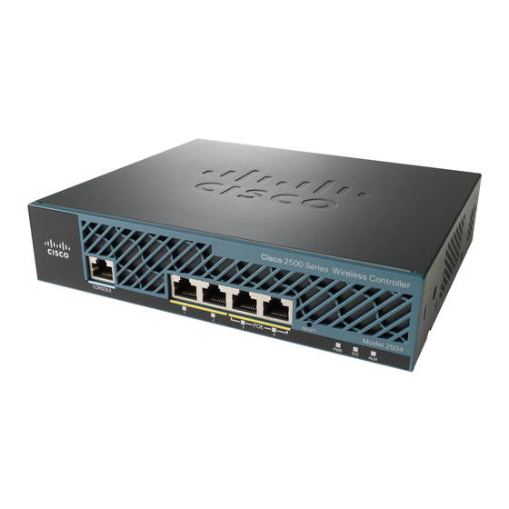
- Page 5 It is expected that there will be small variations in LED color intensity and hue from unit to Note unit. This is within the normal range of the LED manufacturer’s specifications and is not a defect. Figure 2 Front Panel and LEDs CISCO 2500 Series WIRELESS CONTROLLER Model 2504 RESET CONSOLE RESET CONSOLE...
- Page 6 Callout Port and LEDs State and Description GigE port and LED The Gigabit Ethernet port is an RJ-45 connector form-factor. This port is designed so that 1500 VAC rms isolation (per the 802.3 specification) is met between chassis ground and any 48V/Ethernet signal. LED description: •...
- Page 7 Callout Port and LEDs State and Description Reset button Pushing the Reset button reboots the system. RESET Power LED The power LED light is on when all the power conversion circuits are running normally. LED description: • Green—Power is on •...
- Page 8 AC/DC adapter. Power is provided to the system board from the 48 VDC input. There is enough power available to power the system board plus two 802.3af PoE devices. The Cisco 2106 power adapter is not Note compatible with a 2504 controller. Cable Lock slot...
-
Page 9: Package Contents
Step 2 Step 3 Ensure that all items listed in the “Package Contents” section are included in the shipment. Check each item for damage. If any item is damaged or missing, notify your authorized Cisco sales representative. Package Contents Each 2504 controller package contains the following items: •... -
Page 10: Initial System Configuration Information
• A management interface DHCP server IP address, such as 10.40.0.6 (the IP address of the default DHCP server that will supply IP addresses to clients and the management interface. • A virtual gateway IP address (a fictitious, unassigned IP address, such as 1.1.1.1, used by all Cisco wireless controller Layer 3 security and mobility managers). -
Page 11: Choosing A Physical Location
• RADIUS server IP address, communications port, and secret if you are configuring a RADIUS server, such as 10.40.0.3, 1812, and mysecretcode. • The country code for this installation. Enter help to see a list or refer to the Cisco Wireless LAN Controller Configuration Guide for country code information. This guide is available at cisco.com. - Page 12 • Mounting the Controller on a Wall (Rack-Mount Brackets) Mounting the Controller on a Wall (Mounting Screws) • Mounting the Controller in a Rack • Mounting the Controller on a Desktop or Shelf Before mounting the controller on a desktop or shelf, install the rubber feet located in accessory kit shipped with the controller.
- Page 13 The controller can be mounted on a wall using an optional rack-mount bracket kit that is not included with the controller. You can order a kit with 19-inch rack mounting brackets and hardware from Cisco. The kit part number is AIR-CT2504-RMNT. Warning Read the wall-mounting carefully before beginning installation.
- Page 14 Figure 5 Installing the Rack-Mount Brackets to the Sides of the Controller BASE MOUNT #10-32 flat head screws (mounting screws for each side of the controller) Mount the 2504 controller on the wall with the front panel facing down, as shown Figure Step 2 For the best support of the controller and cables, make sure the controller is attached securely...
-
Page 15: Mounting The Controller On A Wall (Mounting Screws)
Figure 6 Mounting the Controller on the Wall Front panel (facing down) Wall mounting screws #10-32 flat head screws After the controller is mounted on the wall, perform the following tasks to complete the Step 3 installation: Connecting the Controller Console Port •... - Page 16 Warning Read the wall-mounting carefully before beginning installation. Failure to use the correct hardware or to follow the correct procedures could result in a hazardous situation to people and damage to the system. Statement 378 To mount the controller on a wall using mounting screws, follow these steps: Step 1 Mark the location of the mounting screws on the wall.
- Page 17 Step 4 Place the controller onto the mounting screws and slide it down until it lock into place, as shown in Figure The front panel of the controller should be facing down. Note Figure 8 Place the Controller on the Mounting Screws Front panel (facing down) Mounting screws After the controller is mounted ion the wall, perform the following tasks to complete the...
- Page 18 Step 6 For configuration instructions about using the CLI setup program, see the “Running the Bootup Script and Power-On Self Test” section on page Mounting the Controller in a Rack To mount the 2504 controller in a 19-inch equipment rack, you can order an optional Optional Rack Mount kit (AIR-CT2504-RMNT).
- Page 19 Figure 9 Attaching the 19-Inch Brackets to the Side of the Controller. RACK MOUNT #10-32 flat head screws (mounting screws for each side of the controller) Step 2 After the brackets are attached to the sides of the controller, insert the controller into the 19-inch rack.
- Page 20 Figure 10 Mounting the Controller in a 19-Inch Rack #10-32 pan-head screws or #12-24 slotted head screws After the controller is mounted in the rack, perform the following tasks to complete the Step 3 installation: Connecting the Controller Console Port •...
-
Page 21: Connecting The Controller Console Port
If the relief clip is not installed, the power connector can be damaged if the power cable is pulled or if the power adapter falls. The Cisco 2106 power adapter is not compatible with a 2504 controller. Note To secure the power adapter cable and plug, follow these steps:... - Page 22 Step 1 Wrap the power adapter cable through the plastic security clip as shown in Figure Figure 11 Plastic Relief Clip Fasten the security clip with a screw to the existing hole on the back panel on the 2504 Step 2 controller (see Figure 12).
-
Page 23: Installing A Security Lock
Security clip secured with screw Power plugged into the POWER 48VDC port. AC/DC power adapter cable Installing a Security Lock The controller has a security slot on the back panel. You can install an optional customer-supplied cable lock, such as the type that is used to secure a laptop computer, to secure the controller. Refer to Figure 3 for the location of the security lock. - Page 24 CISCO SYSTEMS WLCNG Boot Loader Version 1.0.15 (Built on Nov 23 2010 at 07:51:36 by cisco) Board Revision 0.0 (SN: PSJ143302MT, Type: AIR-CT2504-K9) (P) Verifying boot loader integrity... OK.
- Page 25 Validating XML configuration octeon_device_init: found 1 DPs /dev/fpga: No such device or address readCPUConfigData: cardid 0x6060001 Cisco is a trademark of Cisco Systems, Inc. Software Copyright Cisco Systems, Inc. All rights reserved. Cisco AireOS Version 7.0.114.76 Firmware Version PIC 14.0...
- Page 26 Starting Mobility Management: ok Starting Virtual AP Services: ok Starting AireWave Director: ok Starting Network Time Services: ok Starting Cisco Discovery Protocol: ok Starting Broadcast Services: ok Starting Logging Services: ok Starting DHCP Server: ok Starting IDS Signature Manager: ok...
- Page 27 Validating XML configuration octeon_device_init: found 1 DPs /dev/fpga: No such device or address readCPUConfigData: cardid 0x6060001 Cisco is a trademark of Cisco Systems, Inc. Software Copyright Cisco Systems, Inc. All rights reserved. Cisco AireOS Version 7.0.114.76 Firmware Version PIC 14.0...
- Page 28 Starting Mobility Management: ok Starting Virtual AP Services: ok Starting AireWave Director: ok Starting Network Time Services: ok Starting Cisco Discovery Protocol: ok Starting Broadcast Services: ok Starting Logging Services: ok Starting DHCP Server: ok Starting IDS Signature Manager: ok...
-
Page 29: Using The Startup Wizard
If the controller passes the POST, the bootup script runs the Startup Wizard, which prompts Step 6 you for basic configuration information. Welcome to the Cisco Wizard Configuration Tool Use the '-' character to backup System Name [Cisco_d9:16:24]: The startup wizard runs the first time that you power on the controller. The second Note time you power it on, the controller prompts you for a login ID and password. - Page 30 Note Press the hyphen key if you need to return to the previous command line. Table 3 Startup Wizard Information Wizard Setting Action System Name Enter the system name, which is the name you want to assign to the controller. You can enter up to 31 ASCII characters.
- Page 31 Table 3 Startup Wizard Information (continued) Wizard Setting Action Management Interface DHCP Server IP Address Enter the management interface DHCP server IP address. Virtual Gateway IP Address Enter the IP address of the controller virtual interface. You should enter a fictitious, unassigned IP address, such as 1.1.1.1.
- Page 32 Table 3 Startup Wizard Information (continued) Wizard Setting Action Allow Static IP Addresses Enter YES to allow clients to assign their own IP address or no to make clients request an IP address from a DHCP server. Values are YES or no.
-
Page 33: Logging Into The Controller
Table 3 Startup Wizard Information (continued) Wizard Setting Action Enter a polling interval between 3600 and Enter the polling interval between 3600 and 604800 secs 604800 seconds. This prompt only displays if YES was Note entered in the “Configure a NTP Server Now?”... -
Page 34: Connecting To The Network
10/100/1000BASE-T Ethernet (RJ-45 physical port, UTP, Category-5 or higher cable). Always use Category-5, Category-5e, Category-6, or Category-7 Ethernet cables to connect the office network equipment to the controller. Figure 13 External Network Equipment Connection to the Controller Cisco Access Points 10/100/1000BASE-T MDI cable CLI console... -
Page 35: Connecting Access Points
Connecting Access Points After you have configured the controller, use Category-5, Category-5e, Category-6, or Category-7 Ethernet cables to connect up to 50 Cisco lightweight access points to the controller Ethernet ports or to the network (distribution system) as shown in Figure 14. -
Page 36: Using The Reset Button
Table 1 on page 5 for a description of the front panel LEDs. The installation is complete. Refer to the Cisco Wireless Controller Configuration Guide for more information about configuring your controller. The guide is available on cisco.com. Using the Reset Button The Reset button on the front panel of the controller becomes active after the controller boots. -
Page 37: What's New In Cisco Product Documentation
What’s New in Cisco Product Documentation For information on obtaining documentation, submitting a service request, and gathering additional information, see the monthly What’s New in Cisco Product Documentation, which also lists all new and revised Cisco technical documentation, at: http://www.cisco.com/en/US/docs/general/whatsnew/whatsnew.html Subscribe to the What’s New in Cisco Product Documentation as a Really Simple Syndication (RSS) -
Page 38: Translated Safety Warnings
Translated Safety Warnings Statement 1071—Warning Definition Warning IMPORTANT SAFETY INSTRUCTIONS This warning symbol means danger. You are in a situation that could cause bodily injury. Before you work on any equipment, be aware of the hazards involved with electrical circuitry and be familiar with standard practices for preventing accidents. - Page 39 Attention IMPORTANTES INFORMATIONS DE SÉCURITÉ Ce symbole d'avertissement indique un danger. Vous vous trouvez dans une situation pouvant entraîner des blessures ou des dommages corporels. Avant de travailler sur un équipement, soyez conscient des dangers liés aux circuits électriques et familiarisez-vous avec les procédures couramment utilisées pour éviter les accidents.
- Page 40 Advarsel VIKTIGE SIKKERHETSINSTRUKSJONER Dette advarselssymbolet betyr fare. Du er i en situasjon som kan føre til skade på person. Før du begynner å arbeide med noe av utstyret, må du være oppmerksom på farene forbundet med elektriske kretser, og kjenne til standardprosedyrer for å...
- Page 41 Varning! VIKTIGA SÄKERHETSANVISNINGAR Denna varningssignal signalerar fara. Du befinner dig i en situation som kan leda till personskada. Innan du utför arbete på någon utrustning måste du vara medveten om farorna med elkretsar och känna till vanliga förfaranden för att förebygga olyckor.
-
Page 47: Statement 1015-Battery Handling
Statement 1015—Battery Handling Warning There is the danger of explosion if the battery is replaced incorrectly. Replace the battery only with the same or equivalent type recommended by the manufacturer. Dispose of used batteries according to the manufacturer’s instructions. Statement 1015 Waarschuwing Er is ontploffingsgevaar als de batterij verkeerd vervangen wordt. - Page 48 ¡Advertencia! Existe peligro de explosión si la batería se reemplaza de manera incorrecta. Reemplazar la batería exclusivamente con el mismo tipo o el equivalente recomendado por el fabricante. Desechar las baterías gastadas según las instrucciones del fabricante. Varning! Explosionsfara vid felaktigt batteribyte. Ersätt endast batteriet med samma batterityp som rekommenderas av tillverkaren eller motsvarande.
-
Page 49: Statement 1024-Ground Conductor
Statement 1024—Ground Conductor Warning This equipment must be grounded. Never defeat the ground conductor or operate the equipment in the absence of a suitably installed ground conductor. Contact the appropriate electrical inspection authority or an electrician if you are uncertain that suitable grounding is available. Statement 1024 Waarschuwing Deze apparatuur dient geaard te zijn. - Page 50 Advarsel Dette utstyret må jordes. Omgå aldri jordingslederen og bruk aldri utstyret uten riktig montert jordingsleder. Ta kontakt med fagfolk innen elektrisk inspeksjon eller med en elektriker hvis du er usikker på om det finnes velegnet jordning. Aviso Este equipamento deve ser aterrado. Nunca anule o fio terra nem opere o equipamento sem um aterramento adequadamente instalado.
-
Page 52: Statement 1040-Product Disposal
Statement 1040—Product Disposal Warning Ultimate disposal of this product should be handled according to all national laws and regulations. Statement 1040 Waarschuwing Het uiteindelijke wegruimen van dit product dient te geschieden in overeenstemming met alle nationale wetten en reglementen. Varoitus Tämä... - Page 53 Avvertenza Lo smaltimento di questo prodotto deve essere eseguito secondo le leggi e regolazioni locali. Advarsel Endelig kassering av dette produktet skal være i henhold til alle relevante nasjonale lover og bestemmelser. Aviso Deitar fora este produto em conformidade com todas as leis e regulamentos nacionais.
-
Page 55: Statement 371-Power Cable And Ac Adapter
Appliance and Material Safety Law prohibits the use of UL-certified cables (that have the “UL” or “CSA” shown on the cord), not regulated with the subject law by showing “PSE” on the cord, for any other electrical devices than products designated by Cisco. Statement 157—VCCI Compliance for Class B Equipment... - Page 56 Cisco and the Cisco Logo are trademarks of Cisco Systems, Inc. and/or its affiliates in the U.S. and other countries. A listing of Cisco's trademarks can be found at www.cisco.com/go/trademarks. Third party trademarks mentioned are the property of their respective owners. The use of the word...